Groshong Richard H. 3-D Structural Geology(Second Edition)
Подождите немного. Документ загружается.


260 Chapter 8 · Faulted Surfaces
Fig. 8.57. Structure contour map of reverse-faulted marker horizon (thin lines). Faults are thick lines,
hidden contours are dashed
Fig. 8.58. Fault cutoff map, viewed from the hangingwall toward the footwall. The footwall beds have
darker shading than the hangingwall beds. Shaded units are porous and permeable; unshaded units are
impermeable
261
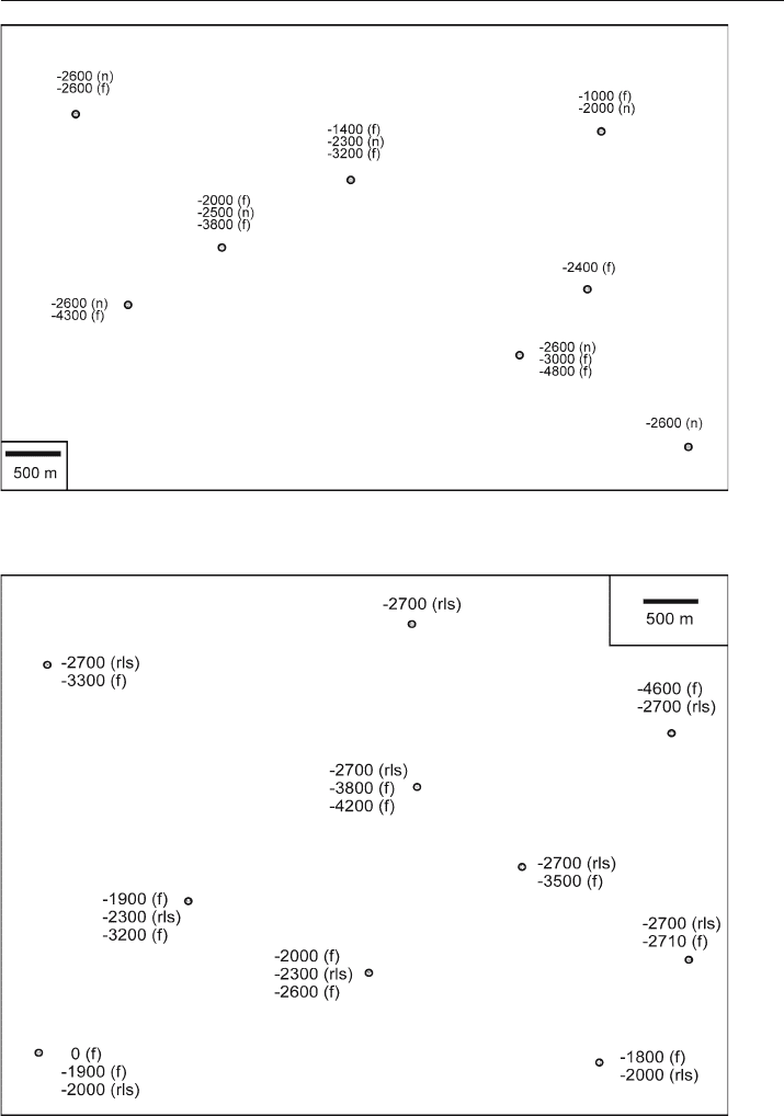
Fig. 8.59. Top of the Northriver Sandstone (n) and fault-cut elevations (f) in wells. Elevations are in
meters, negative below sea level
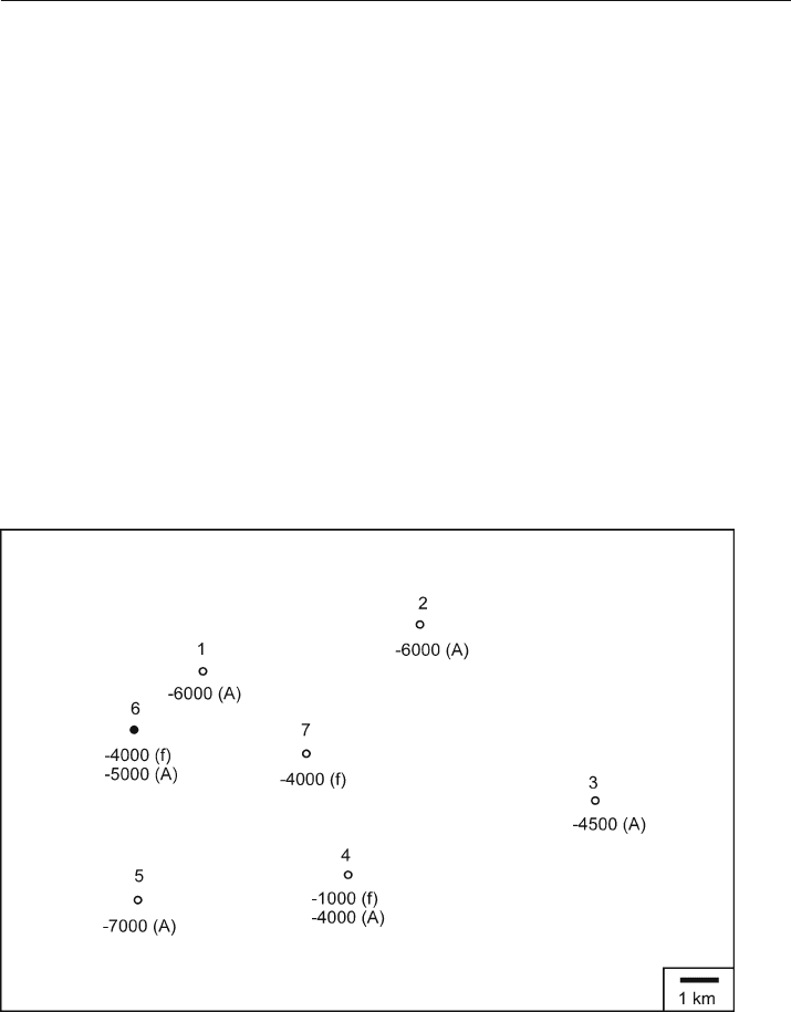
Fig. 8.60. Map giving the top of the Reef Limestone (rls) and faults (f) in wells. Elevations are in meters,
negative below sea level
8.8 · Exercises

262 Chapter 8 · Faulted Surfaces
8.8.13
Branching Fault
Map the faults and the top of the Reef Limestone on the map of Fig. 8.60. Where is
the branch line? What is the attitude of the limestone away from the faults? What
is the attitude of the limestone between the faults? What are the attitudes of the
faults?
8.8.14
Splay Faults
The water
-well map of Fig. 8.61 shows a distinctive clay seam to be absent in some
wells due to faulting. Map the faults and the top of the clay seam. Where is the branch
line? What are the attitudes of the faults? What is the maximum throw and heave on
the clay seam? If the clay seam is a barrier to ground water flow from the surface, where
is this barrier absent? Is a spill of toxic heavy liquid in the southwest corner of the map
area likely to sink below the clay seam? Why or why not? In which direction will a spill
of heavy liquid in the southeast corner of the map migrate?
Fig. 8.61. Map of the top of a clay seam in water wells drilled into an alluvial aquifer. Elevations below
sea level are negative
263
8.8.15
Sequential Faults 1
Two different fault trends occur in the area of Fig. 8.62. Map the faults and the A sand.
What is the reason for the hydrocarbon trap in the A sand? What are the attitudes of
the faults? What is the throw and heave on each fault? Which fault is older? If the hy-
drocarbons migrated before the formation of the younger fault, would the trapping
potential of the structures be the same?
8.8.16
Sequential Faults 2
Contour the Northport Dolomite in the map of Fig. 8.63, being careful to explain
the fault cuts and the oil trap(s). Is there one oil field or two? What are the attitudes
of the faults? What is the throw and heave on each fault? Which fault is older? If
the hydrocarbons migrated before the formation of the younger fault, would the trap-
ping potential of the structures be the same? Are there any additional hydrocarbon
prospects?
Fig. 8.62. Map of the top of the A sand (A) and faults (f) in wells drilled for oil. The solid circle is an oil
well, open circles are dry holes. Everywhere away from the faults clear bedding dips are recorded on the
dipmeter; they are about 27, 334. Close to the fault in well 4 the bedding dip is at azimuth 062. In well 6
the bedding dip close to the fault is at azimuth 189. In well 7 the dips of bedding are in all directions
near the fault. Elevations are in meters, negative below sea level
8.8 · Exercises

264 Chapter 8 · Faulted Surfaces
Fig. 8.63. Map of well information from the Northport Dolomite. Two numbers together next to a well
give fault cut information: 500, 100: depth of fault cut, amount of fault cut. A single number by the well
is the top of the dolomite. Where only fault-cut information is given, the dolomite is faulted out. The
fault trends are generally northwest–southeast. Elevations are in feet, negative below sea level

Chapter 9
9.1
Introduction
The three-dimensional geometry of a structure can be determined from the bedding
attitudes measured in a single well bore or on a traverse through a structure. The method
of dip sequence analysis presented here was developed for the structural analysis of
dipmeter logs by Bengtson (1981a) but is equally informative whether the traverse is
down a well or along a stream. Major problems with the structural interpretation of
dip data are the high stratigraphic noise content and the complexity of the structures
to be interpreted. Dip sequence analysis techniques, called Statistical Curvature Analysis
Techniques (SCAT or SCAT analysis) by Bengtson (1981a), are particularly good for
extracting the structural signal from the noise. Using SCAT it is possible to determine
the plunge of folds, the locations of fold axial surfaces, crests, and troughs, to infer the
strike and dip directions of faults, and to separate regional fold trends from local fault
trends. The power of the technique derives from (1) the noise
-reduction strategy of
examining the data as dip components in both the strike and dip directions of folding
and (2) providing models for the SCAT responses of the geometry to be interpreted.
Dip-Sequence Analysis
Fig. 9.1. Railroad Gap Field, California, predicted longitudinal and transverse cross sections and struc-
ture contour map on the top Carneros sandstone, based on the SCAT analysis of a single well at the crest
of the anticline. O/W: oil-water contact. (After Bengtson 1981a)

266 Chapter 9 · Dip-Sequence Analysis
Fig. 9.2. SCAT plots for the discovery well of Railroad Gap Field, California. For the map and cross
sections see Fig. 9.1. a Dip component vs. depth plots. b Dip vs. azimuth plots. (After Bengtson 1981a)
267
The potential of the method is indicated by the interpretation of the Railroad Gap oil
field on the basis of the SCAT analysis of a single, favorably located well (Figs. 9.1, 9.2).
SCAT analysis (Bengtson 1981a) was used to predict the structure on perpendicular
cross sections from which the map was generated. The map view shows the close cor-
respondence between the predicted and observed oil
-water contact.
9.2
Curvature Models
Figure 9.3 illustrates the basic curvature geometries. The first step in the analysis is to
differentiate a monoclinal dip sequence from a fold. This is accomplished with an
azimuth histogram and/or with a tangent diagram. An azimuth histogram is a plot of
the azimuth of the dip versus the amount of the dip (Fig. 9.4). The natural variation of
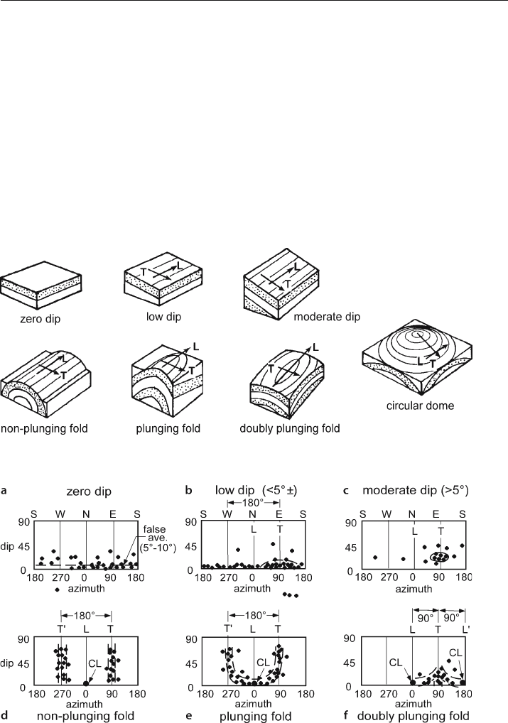
Fig. 9.3. Models of structural curvature geometries. L: Longitudinal; T: transverse. (Bengtson 1981a)
Fig. 9.4. Dip vs. azimuth patterns corresponding to the models of Fig. 9.3. CL: crestal line (after Bengtson
1981a). a Zero dip. b Low dip. c Moderate dip. d Non-plunging fold. e Plunging fold. f Doubly plunging fold
9.2 · Curvature Models
268 Chapter 9 · Dip-Sequence Analysis
dips around a monoclinal dip gives a horizontal distribution of noise. Thus a zero true
dip gives a small false positive average on the azimuth histogram because all dips are
recorded as positive (Fig. 9.4a). As the dip increases the dips form point concentra-
tions that become better defined as the true dip increases (Fig. 9.4b,c). Non
-plunging
and uniformly plunging folds give vertical concentrations of points corresponding to
the limbs (Fig. 9.4d,e) and a doubly plunging fold produces an arrow-head-shaped
distribution of points (Fig. 9.4f). On a tangent diagram a monocline plots as a point
concentration of dips, and a fold (Figs. 5.3, 5.5) will produce a linear or curvilinear
concentration of points.
9.3
Dip Components
A key step in a SCAT analysis is to determine the dip components in the transverse
direction (T = transverse = regional dip) and the longitudinal direction (L =longi-
tudinal = regional strike) which is at right angles to it. These dip components repre-
sent the dips on vertical cross sections in the T and L directions and are used to pro-
duce the SCAT histograms (Fig. 9.2) and cross sections (Fig. 9.1) in the T and L direc-
tions. The T and L directions are found from the dip vs. azimuth histogram (Fig. 9.4)
or from the plot of bedding dips on a tangent diagram (Fig. 9.5). For monoclinal dip,
the center of the point concentration on the dip
-azimuth histogram is the T direction
and the L direction is 90° away from it (Fig. 9.4b,c). For a fold, the center of the limb
concentrations on an azimuth histogram is the T direction and the midpoint between
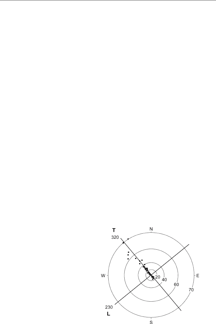
the concentrations is the L direction (Fig. 9.4d–f). On a tangent diagram (Fig. 9.5), the
orientation of the crest (or trough) line is the L direction and the T direction is at right
angles to the crest (or trough) line. Both the T and L lines go through the center of the
tangent diagram regardless of the fold plunge.
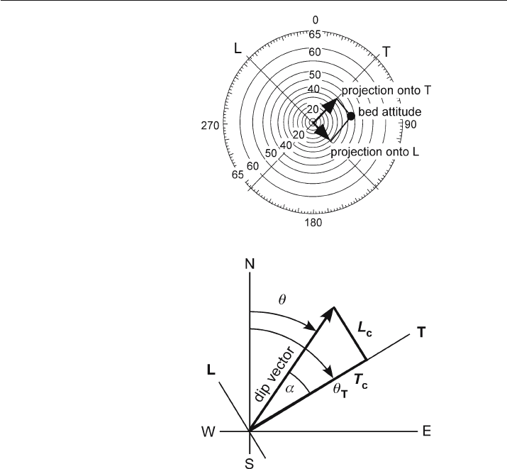
The dip components can be found either graphically or analytically. In the graphi-
cal method, the T and L lines are drawn on a tangent diagram. The T and L components
are the projections of the dip vectors onto the T and L axes (Fig. 9.6). The dip com-
Fig. 9.5.
Determination of T and L di-
rections on the tangent dia-
gram of a fold. Solid dots
represent dip vectors of
bedding
269
ponents are themselves vectors and have both magnitude and direction. The quadrant
of the component, as well as its magnitude, must be recorded.
The dip components can easily be found analytically. Based on the geometry of Fig. 9.7,
α
=
θ
T
–
θ
, (9.1)
T
c
=
δ
cos
α
, (9.2)
L
c
=
δ
sin
α
, (9.3)
where T
c
= T component, L
c
= L component,
α
= angle between dip vector and
T direction,
θ
T
= azimuth of T direction,
θ
= azimuth of dip vector,
δ
= dip. Computer
programs for the preparation of SCAT diagrams have been published by Elphick (1988).
SCAT analysis can be performed entirely on a spreadsheet. Plot the tangent diagram
as described in Sect. 2.8, use Eqs. 9.1–9.3 to find the T and L components, and plot the
dip
-component diagrams as xy graphs.
Fig. 9.6.
Dip components in T and L di-
rections. Here the T direction
is NE–SW and the L direction
is NW–SE. Bed attitude is
55, 082. The dip components
are the lengths found by or-
thogonal projection of the dip
vector onto the T and L lines.
The T component is 50°NE
and the L component is 40°SE
Fig. 9.7.
Geometry of the T and L com-
ponents.
α
: angle between
dip vector and T direction;
θ
T
: azimuth of T direction;
θ
: azimuth of dip vector;
T
c
: T component; L
c
: L com-
ponent
9.3 · Dip Components
