Gibilisco S. Teach Yourself Electricity and Electronics
Подождите немного. Документ загружается.

Problem 17-4
Suppose a circuit has an absolute-value impedance Z of 100 Ω, with a resistance R = 80 Ω. What is
the power factor?
Simply find the ratio PF = R/Z = 80/100 = 0.8 = 80%. Note that it doesn’t matter whether the
reactance in this circuit is capacitive or inductive.
Problem 17-5
Suppose a circuit has an absolute-value impedance of 50 Ω, purely resistive. What is the power factor?
Here, R = Z = 50 Ω. Therefore, PF = R/Z = 50/50 = 1 = 100%.
Problem 17-6
Suppose a circuit has a resistance of 50 Ω and a capacitive reactance of −30 Ω in series. What is the
power factor? Use the cosine method.
First, find the phase angle. Remember the formula: φ=arctan (X/R), where X is the reactance
and R is the resistance. Therefore, φ=arctan (−30/50) = arctan (−0.60) =−31°. The power factor
is the cosine of this angle; PF = cos (−31°) = 0.86 = 86%.
Problem 17-7
Suppose a circuit has a resistance of 30 Ω and an inductive reactance of 40 Ω. What is the power
factor? Use the R/Z method.
Find the absolute-value impedance: Z
2
= R
2
+ X
2
= 30
2
+ 40
2
= 900 + 1600 = 2500. There-
fore, Z = 2500
1/2
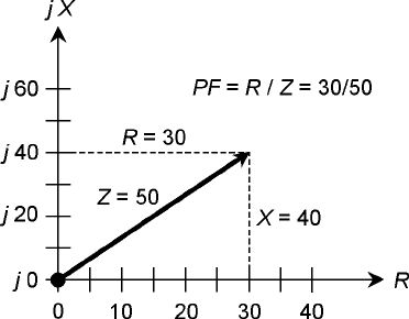
= 50 Ω, so PF = R/Z = 30/50 = 0.60 = 60%. This problem can be represented vec-
torially by a 30:40:50 right triangle, as shown in Fig. 17-8.
How Much of the Power Is True?
The preceding formulas allow you to figure out, given the resistance, reactance, and VA power, how
many watts are true or real power, and how many watts are imaginary or reactive power. This is im-
portant in RF equipment, because some RF wattmeters display VA power rather than true power.
When there is reactance in a circuit or system, the wattage reading is therefore exaggerated.
True Power, VA Power, and Reactive Power 271
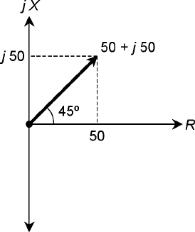
17-7 Vector diagram
showing the phase
angle for a complex
impedance of 50 +
j50. The R and jX
scales are relative.
Problem 17-8
Suppose a circuit has 50 Ω of resistance and 30 Ω of inductive reactance in series. A wattmeter
shows 100 W, representing the VA power. What is the true power?
First, calculate the power factor. Suppose you use the phase-angle method. Then:
φ=arctan (X/R )
= arctan (30/50) = 31°
The power factor is the cosine of the phase angle. Thus:
PF = cos 31°=0.86 = 86%
Remember that PF = P
T
/P
VA
. This formula can be rearranged to solve for true power:
P
T
= PF × P
VA
= 0.86 × 100
= 86 W
Problem 17-9
Suppose a circuit has a resistance of 1000 Ω in parallel with a capacitance of 1000 pF. The frequency
is 100 kHz. If a wattmeter designed to read VA power shows a reading of 88.0 W, what is the true
power?
This problem is rather complicated because the components are in parallel. To begin, be sure
the units are all in agreement so the formulas will work right. Convert the frequency to megahertz:
f = 100 kHz = 0.100 MHz. Convert capacitance to microfarads: C = 1000 pF = 0.001000 µF. Fr o m
the previous chapter, recall the formula for capacitive susceptance, and calculate it for this situation:
B
C
= 6.28fC
= 6.28 × 0.100 × 0.001000
= 0.000628 S
272 Power and Resonance in Alternating-Current Circuits
17-8 Illustration for
Problem 17-7. (The
vertical and horizontal
scale increments differ;
this is a common
practice in graphs,
often done for
illustration
convenience.)
The conductance of the resistor, G, is the reciprocal of the resistance, R, as follows:
G = 1/R
= 1/1000
= 0.001000 S
Now, use the formulas for calculating resistance and reactance in terms of conductance and suscep-
tance in parallel circuits. First, find the resistance:
R = G/(G
2
+ B
2
)
= 0.001000/(0.001000
2
+ 0.000628
2
)
= 0.001000/0.000001394
= 717 Ω
Then, find the reactance:
X =−B/(G
2
+ B
2
)
=−0.000628/0.000001394
=−451 Ω
Next, calculate the phase angle:
φ=arctan (X/R)
= arctan (−451/717)
= arctan (−0.629)
=−32.2°
The power factor is found from the phase angle as follows:
PF = cos φ
= cos (−32.2°)
= 0.846 = 84.6%
The VA power, P
VA
, is given as 88.0 W. Therefore:
P
T
= PF × P
VA
= 0.846 × 88.0
= 74.4 W
Power Transmission
Consider how electricity gets to your home. Generators produce large voltages and currents at a power
plant. The problem: getting the electricity from the plant to the homes, businesses, and other facilities
that need it. This process involves the use of long wire transmission lines. Transformers are also required
to step the voltages up or down. As another example, consider a radio broadcast or communications sta-
tion. The transmitter produces high-frequency ac. The problem is getting the power to be radiated by
Power Transmission 273
the antenna, located some distance from the transmitter. This involves the use of an RF transmission
line. The most common type is coaxial cable. Two-wire line is also sometimes used. At ultrahigh and
microwave frequencies, another kind of transmission line, known as a waveguide, is often employed.
Loss: The Less, The Better!
The overriding concern in any power transmission system is minimizing the loss. Power wastage
occurs almost entirely as heat in the transmission line conductors and dielectric, and in objects near
the line. Some loss can take the form of unwanted electromagnetic radiation from the line. Loss also
occurs in transformers. Power loss in an electrical system is analogous to the loss of usable work pro-
duced by friction in a mechanical system. The less of it, the better!
In an ideal power transmission system, all of the power is VA power; that is, it is in the form of
ac in the conductors and an alternating voltage between them. It is undesirable to have power in a
transmission line or transformer exist in the form of true power, because that translates into either
heat loss, or radiation loss, or both. The place for true power dissipation or radiation is in the load,
such as electrical appliances or radio antennas.
Power Measurement in a Transmission Line
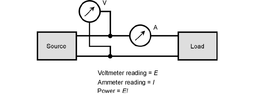
In an ac transmission line, power is measured by placing an ac voltmeter between the conductors,
and an ac ammeter in series with one of the conductors (Fig. 17-9). Then the power P (in watts) is
equal to the product of the rms voltage E (in volts) and the rms current I (in amperes). This tech-
nique can be used in any transmission line. But this is not necessarily an indication of the true power
dissipated by the load at the end of the line.
Recall that any transmission line has a characteristic impedance. This value, Z
o
, depends on the
diameters of the line conductors, the spacing between the conductors, and the type of dielectric ma-
terial that separates the conductors. If the load is a pure resistance R containing no reactance, and if
R = Z
o
, then the power indicated by the voltmeter/ammeter scheme will be the same as the true
power dissipated by the load—provided that the voltmeter and ammeter are placed at the load end
of the transmission line.
274 Power and Resonance in Alternating-Current Circuits
17-9 Power measurement in a transmission line. Ideally, the voltage and
the current should be measured at the same physical point on the
line.
If the load is a pure resistance but it differs from the characteristic impedance of the line, then
the voltmeter and ammeter will not give an indication of the true power. Also, if there is any reac-
tance in the load, the voltmeter/ammeter method will not be accurate, even if the resistive compo-
nent happens to be the same as the characteristic impedance of the line. The physics of this is rather
complicated, and we won’t get into the details here. But you should remember that it is optimum
for the impedance of a load to be a pure resistance R, such that R = Z
o
. When this is not the case, an
impedance mismatch is said to exist.
Small impedance mismatches can often be tolerated in power transmission systems. But this is
not always the case. In very high frequency (VHF), ultrahigh frequency (UHF), and microwave
radio transmitting systems, even a small impedance mismatch between the load and the line can
cause excessive power losses in the line. An impedance mismatch can usually be corrected by means
of a matching transformer between a transmission line and the load, and/or the deliberate addition
of reactance at the load end of the line to cancel out any existing load reactance.
Loss in a Mismatched Line
When a transmission line is terminated in a resistance R = Z
o
, then the current and the voltage are
constant all along the line, provided the line has no loss. The ratio of the voltage to the current, E/I,
is equal to R and also equal to Z
o
. But this is an idealized case. No line is completely lossless.
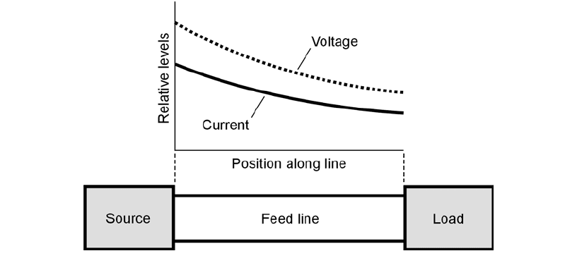
In a real-world transmission line, the current and voltage gradually decrease as a signal makes
its way from the source to the load. But if the load is a pure resistance equal to the characteristic
impedance of the line, the current and voltage remain in the same ratio at all points along the line
(Fig. 17-10).
Standing Waves
If the load is not perfectly matched to the line, the current and voltage vary in a complicated way
along the length of the line. In some places, the current is high; in other places it is low. The max-
Power Transmission 275
17-10 In a matched line, the ratio of the voltage to the current (E/I ) is
constant everywhere along the line, although the actual values of
E and I decrease with increasing distance from the source.
ima and minima are called loops and nodes, respectively. At a current loop, the voltage is minimum (a
voltage node), and at a current node, the voltage is maximum (a voltage loop). The current and volt-
age loops and nodes along a mismatched transmission line, if graphed as functions of the position
on the line, form wavelike patterns that remain fixed over time. They just stand there. For this rea-
son, they are called standing waves.
Standing-Wave Loss
At current loops, the loss in line conductors reaches a maximum. At voltage loops, the loss in the
dielectric reaches a maximum. At current nodes, the loss in the conductors reaches a minimum. At
voltage nodes, the loss in the dielectric reaches a minimum. It is tempting to suppose that every-
thing would average out here, but it doesn’t work that way! Overall, in a mismatched line, the line
losses are greater than they are in a perfectly matched line. This extra line loss increases as the mis-
match gets worse.
Transmission-line mismatch loss, also called standing-wave loss, occurs in the form of heat dissipa-
tion. It is true power. Any true power that goes into heating up a transmission line is wasted, because
it cannot be dissipated in the load.
The greater the mismatch, the more severe the standing-wave loss becomes. The more loss a line
has to begin with (that is, when it is perfectly matched), the more loss is caused by a given amount
of mismatch. Standing-wave loss also increases as the frequency increases, if all other factors are held
constant. This loss is the most significant, and the most harmful, in long lengths of transmission
line, especially in RF practice at VHF, UHF, and microwave frequencies.
Line Overheating
A severe mismatch between the load and the transmission line can cause another problem: physical
damage to, or destruction of, the line!
A feed line might be able to handle a kilowatt (1 kW) of power when it is perfectly matched.
But if a severe mismatch exists and you try to feed 1 kW into the line, the extra current at the cur-
rent loops can heat the conductors to the point where the dielectric material melts and the line
shorts out. It is also possible for the voltage at the voltage loops to cause arcing between the line con-
ductors. This perforates and/or burns the dielectric, ruining the line.
When an RF transmission line must be used with a mismatch, derating functions are required to
determine how much power the line can safely handle. Manufacturers of prefabricated lines such as
coaxial cable can supply you with this information.
Resonance
One of the most important phenomena in ac circuits, especially in RF engineering, is the property
of resonance. This is a condition that occurs when capacitive and inductive reactance cancel each
other out.
Series Resonance
Recall that capacitive reactance, X
C
, and inductive reactance, X
L
, can be equal in magnitude, al-
though they are always opposite in effect. In any circuit containing an inductance and capacitance,
there exists a frequency at which X
L
=−X
C
. This condition constitutes resonance. In a simple LC cir-
cuit, there is only one such frequency. But in some circuits involving transmission lines or antennas,
276 Power and Resonance in Alternating-Current Circuits
there can be many such frequencies. The lowest frequency at which resonance occurs is called the
resonant frequency, symbolized f
o
.
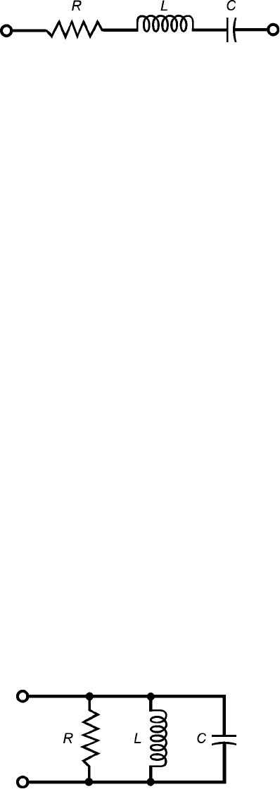
Refer to the schematic diagram of Fig. 17-11. You should recognize this as a series RLC circuit.
At some particular frequency, X
L
=−X
C
. This is inevitable if L and C are finite and nonzero. This fre-
quency is f
o
for the circuit. At f
o
, the effects of capacitive reactance and inductive reactance cancel out.
The result is that the circuit appears as a pure resistance, with a value that is theoretically equal to R.
If R = 0, that is, if the resistor is a short circuit, then the circuit is called a series LC circuit, and
the impedance at resonance will be theoretically 0 + j 0. The circuit will offer no opposition to the
flow of alternating current at the frequency f
o
. This condition is series resonance. In a practical series
LC circuit, there is always a little bit of loss in the coil and capacitor, so the real part of the complex
impedance is not exactly equal to 0 (although it can be extremely small).
Parallel Resonance
Refer to the circuit diagram of Fig. 17-12. This is a parallel RLC circuit. Remember that, in this sort
of situation, the resistance R should be thought of as a conductance G, with G = 1/R. Then the cir-
cuit can be called a parallel GLC circuit.
At some particular frequency f
o
, the inductive susceptance B
L
will exactly cancel the capacitive
susceptance B
C
; that is, B
L
=−B
C
. This is inevitable for some frequency f
o
, as long as the circuit con-
tains finite, nonzero inductance and finite, nonzero capacitance. At the frequency f
o
, the suscep-
tances cancel each other out, leaving theoretically zero susceptance. The admittance through the
circuit is then very nearly equal to the conductance, G, of the resistor.
If the circuit contains no resistor, but only a coil and capacitor, it is called a parallel LC circuit,
and the admittance at resonance will be theoretically 0 + j0. That means the circuit will offer great
opposition to alternating current at f
o
, and the complex impedance will theoretically be infinite!
This condition is parallel resonance. In a practical parallel LC circuit, there is always a little bit of loss
in the coil and capacitor, so the real part of the complex impedance is not infinite (although it can
be extremely large).
Calculating Resonant Frequency
The formula for calculating resonant frequency f
o
, in terms of the inductance L in henrys and the
capacitance C in farads, is as follows:
f
o
= 1/[2π(LC )
1/2
]
Resonance 277
17-11 A series RLC circuit.
17-12 A parallel RLC
circuit.

Considering π=3.14 to three significant figures, this formula can be simplified to:
f
o
= 0.159/(LC )
1/2
The
1
⁄2 power of a quantity represents the positive square root of that quantity. The preceding for-
mulas are valid for series-resonant and parallel-resonant RLC circuits.
The formula will also work if you want to find f
o
in megahertz (MHz) when L is given in mi-
crohenrys (µH) and C is in microfarads (µF). These values are far more common than hertz, hen-
rys, and farads in electronic circuits. Just remember that millions of hertz go with millionths of
henrys, and with millionths of farads.
The Effects of R and G
Interestingly, the value of R or G does not affect the resonant frequency in either type of circuit. But
these quantities are significant, nevertheless! The presence of nonzero resistance in a series-resonant
circuit, or nonzero conductance in a parallel-resonant circuit, makes the resonant frequency less well-
defined. Engineers say that the resonant frequency response becomes “more broad” or “less sharp.”
In a series circuit, the resonant frequency response becomes more broad as the resistance in-
creases. In a parallel circuit, the resonant frequency response becomes more broad as the conductance
increases. The sharpest possible responses occur when R = 0 in a series circuit, and when G = 0 (that
is,R= ) in a parallel circuit.
Problem 17-10
Find the resonant frequency of a series circuit with an inductance of 100 µH and a capacitance of
100 pF.
First, convert the capacitance to microfarads: 100 pF = 0.000100 µF. Then find the product
LC = 100 × 0.000100 = 0.0100. Take the square root of this, getting 0.100. Finally, divide 0.159 by
0.100, getting f
o
= 1.59 MHz.
Problem 17-11
Find the resonant frequency of a parallel circuit consisting of a 33-µH coil and a 47-pF capacitor.
Again, convert the capacitance to microfarads: 47 pF = 0.000047 µF. Then find the product
LC = 33 × 0.000047 = 0.00155. Take the square root of this, getting 0.0394. Finally, divide 0.159
by 0.0394, getting f
o
= 4.04 MHz.
Problem 17-12
Suppose you want to design a circuit so that it has f
o
= 9.00 MHz. You have a 33-pF fixed capacitor
available. What size coil will be needed to get the desired resonant frequency?
Use the formula for the resonant frequency, and plug in the values. This will allow you to use
simple arithmetic to solve for L. Convert the capacitance to microfarads: 33 pF = 0.000033 µF.
Then calculate as follows:
f
o
= 0.159/(LC )
1/2
9.00 = 0.159/(L × 0.000033)
1/2
9.00
2
= 0.159
2
/(0.000033 × L)
81.0 = 0.0253/(0.000033 × L)
278 Power and Resonance in Alternating-Current Circuits
81.0 × 0.000033 × L = 0.0253
0.00267 × L = 0.0253
L = 0.0253/0.00267
= 9.48 µH
Problem 17-13
Suppose a circuit must be designed to have f
o
= 455 kHz. A coil of 100 µH is available. What size
capacitor is needed?
Convert the frequency to megahertz: 455 kHz = 0.455 MHz. Then the calculation proceeds in
the same way as with the preceding problem:
f
o
= 0.159/(LC )
1/2
0.455 = 0.159/(100 × C )
1/2
0.455
2
= 0.159
2
/(100 × C )
0.207 = 0.0253/(100 × C )
0.207 × 100 × C = 0.0253
20.7 × C = 0.0253
C = 0.0253/20.7
= 0.00122 µF
= 1220 pF
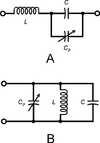
In practical circuits, variable inductors and/or variable capacitors are often placed in tuned circuits,
so that small errors in the frequency can be compensated for. The most common approach is to
design the circuit for a frequency slightly higher than f
o
, and to use a padder capacitor in parallel with
the main capacitor (Fig. 17-13).
Resonance 279
17-13 Padding capacitors
(C
p
) allow limited
adjustment of the
resonant frequency in
a series LC circuit
(as shown at A), or in
a parallel LC circuit
(as shown at B).
Resonant Devices
Resonant circuits often consist of coils and capacitors in series or parallel, but there are other kinds
of hardware that exhibit resonance. Some of these are as follows.
Piezoelectric Crystals
Pieces of quartz, when cut into thin wafers and subjected to voltages, will vibrate at high frequencies.
Because of the physical dimensions of such a piezoelectric crystal, these vibrations occur at a precise fre-
quency f
o
, and also at whole-number multiples of f
o
. These multiples, 2f
o
, 3f
o
, 4f
o
, and so on, are called
harmonic frequencies or simply harmonics. The frequency f
o
is called the fundamental frequency or sim-
ply the fundamental. The fundamental, f
o
, is defined as the lowest frequency at which resonance oc-
curs. Quartz crystals can be made to act like LC circuits in electronic devices. A crystal exhibits an
impedance that varies with frequency. The reactance is zero at f
o
and the harmonic frequencies.
Cavities
Lengths of metal tubing, cut to specific dimensions, exhibit resonance at very high, ultrahigh, and
microwave radio frequencies. They work in much the same way as musical instruments resonate
with sound waves. But the waves are electromagnetic, rather than acoustic. Such cavities, also called
cavity resonators, have reasonable physical dimensions at frequencies above about 150 MHz. Below
this frequency, a cavity can be made to work, but it is long and unwieldy. Like crystals, cavities res-
onate at a fundamental frequency f
o
, and also at harmonic frequencies.
Sections of Transmission Line
When a transmission line is cut to
1
⁄4 wavelength, or to any whole-number multiple of this, it
behaves as a resonant circuit. The most common length for a transmission-line resonator is a
1
⁄4 wavelength. Such a piece of transmission line is called a quarter-wave section.
When a quarter-wave section is short-circuited at the far end, it acts like a parallel-resonant LC
circuit, and has a high resistive impedance at the resonant frequency f
o
. When it is open at the far
end, it acts as a series-resonant LC circuit, and has a low resistive impedance at f
o
. In effect, a quarter-
wave section converts an ac short circuit into an ac open circuit and vice versa, at a specific
frequency f
o
.
The length of a quarter-wave section depends on the desired f
o
. It also depends on how fast the
electromagnetic energy travels along the line. This speed is specified in terms of a velocity factor,
abbreviated v. The value of v is given as a fraction of the speed of light. Typical transmission lines
have velocity factors ranging from about 0.66 to 0.95 (or 66 percent to 95 percent). This factor is
provided by the manufacturers of prefabricated lines such as coaxial cable.
If the frequency in megahertz is f
o
and the velocity factor of a line is v, then the length L
ft
of a
quarter-wave section of transmission line, in feet, is given by this formula:
L
ft
= 246v/f
o
The length L
m
in meters is given by this:
L
m
= 75.0v/f
o
We use L here to stand for “length,” not “inductance”!
280 Power and Resonance in Alternating-Current Circuits
