Fishwick P.A. (editor) Handbook of Dynamic System Modeling
Подождите немного. Документ загружается.


37
On Simulation of
Simulink
®
Models for
Model-Based Design
Rohit Shenoy
The MathWorks Inc.
Brian McKay
The MathWorks Inc.
Pieter J. Mosterman
The MathWorks Inc.
37.1 Introduction .................................................................37-1
37.2 The Case Study Example .............................................37-3
Feedback Control
37.3 Designing with Simulation...........................................37-4
37.4 Obtaining Computational Models ..............................37-4
Modeling from First Principles
•
Using Data and
Simulation to Obtain or Tune Models
37.5 The Robotic Arm Model ..............................................37-7
The Mechanical Model of Arm
•
Electromechanical
Model of the Motor and Coupling
•
Tuning the Motor
Parameters with Data
•
Generating the Motor Models
from Data
37.6 Using Computational Models for Control Design .....37-12
Designing Controllers through Modeling and
Simulation
•
Linearizing Models for Control
System Design
•
Designing a Controller
•
Tuning
Controller Designs Using Optimization Techniques
37.7 Testing with Model-Based Design ...............................37-16
Requirements-Based Testing through Simulation
•
Simulation with Hardware and Implemented Designs
•
Other Uses of Rapid Prototyping in the Design Process
37.8 Conclusions ..................................................................37-19
37.1 Introduction
To remain competitive and reduce cost, industry increasingly relies on computational models (Mosterman,
2004). Designing computational models and using numerical simulation is an alternative to building
hardware prototypes for testing purposes. Computational modeling (Aberg and Gage, 2004; Breunese
et al., 1995; Cellier et al., 1996; Culley and Wallace, 1994) has a number of advantages over traditional
engineering methods, such as:
•
Computational models tend to be less expensive to produce and easier to modify.
•
The ease of modification enables answering “what-if” questions by facilitating rapid exploration of
design options, a task that is time consuming and expensive with physical prototypes. Additionally,
some experiments require multiple simulations with different parameters which can be performed
through Monte Carlo simulations. This is impossible with physical prototypes because these are
prohibitively expensive.
37-1
37-2 Handbook of Dynamic System Modeling
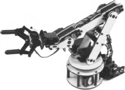
FIGURE 37.1 A robotic arm.
•
In the case of complex systems such as aircraft, power grids, and communication networks, simula-
tion enables unstable and emergency modes to be tested more safely, without risk to infrastructure
or human life.
•
Simulation of such unstable and emergency modes is also an order of magnitude less expensive. For
example, testing an aircraft to failure would cost much more than simulating such an experiment,
which, if the failure would lead to a crash and loss of life, would not be possible otherwise.
•
Modern computational packages allow engineers to employ designs that have been used in
simulation and use them in the eventual product. This is a major time-saving feature.
Building dynamic models in software is part of Model-Based Design (Barnard, 2004), which has all
the merits listed above and is being adopted by engineers in many fields, in particular, the aerospace
and automotive industry. It can be applied to applications such as feedback control, communications,
signal and image processing, and financial modeling. Model-Based Design with Simulink
®
(2006) enables
design, analysis, and simulation of processes in a safe software environment. Consider the example of a
robotic arm designed for use in a production plant, shown in Figure 37.1. Creating a physical prototype
would be expensive and time consuming. Testing it could be dangerous if the robot malfunctioned. The
alternative is to model the mechanical, electrical, and electronic components of the robot in software, and
then use the model to test the algorithms through simulation.
Model-Based Design enables continuous testing as algorithms and computational models are cre-
ated and refined. The integration of testing into the design process can identify problems sooner than
approaches that do not use modeling and simulation. Furthermore, tests can be designed earlier in the
overall design process, which is particularly advantageous if carried out in parallel with other design tasks.
Finally, Model-Based Design with Simulink provides the capability to generate computer code such as C
or C++ from algorithms and computational system models, and use that code for implementation and
testing. In particular, hardware-in-the-loop simulation which uses a real-time computational model of a
physical system will be discussed as well as the systematic testing process of a designed system (Mosterman,
2004). These aspects help bridge the gap between the software and hardware design.
This chapter outlines workflow and software tools for computational modeling and numerical sim-
ulation of dynamic systems with MATLAB
®
(2006) and Simulink. It will not concentrate on the
detailed methodological and technological aspects of numerical simulation of systems with combined
continuous-time and discrete-event behavior, so-called hybrid dynamic systems (Mosterman and Biswas,

On Simulation of Simulink
®
Models for Model-Based Design 37-3
2002). Instead, one of the key goals of the chapter is to explain the selection criteria for modeling tech-
niques based on simulation, design, and testing needs. Section 37.2 examines a robotic arm as a case study
and several examples with the goal of understanding different modeling techniques. Section 37.3 dis-
cusses how simulation can be used in control system design. Section 37.4 presents the modeling, spectrum
spanning first-principles modeling from equations, physics-based modeling, and data-driven modeling.
Section 37.5 applies the different modeling approaches to the robotic arm of the case study. Section 37.6
discusses further usages of simulation in control system design. Section 37.7 gives an overview of the use
of testing as a simulation tool in the design of control systems. Section 37.8 presents the conclusions of
this work.
37.2 The Case Study Example
A robotic arm application, shown in Figure 37.1, is used as a case study because it is relatively generic and
so will reduce the need for discussing overwhelming engineering theory. The robotic arm is a commercial
off-the-shelf product.
1
It consists of a turntable base, an “upper arm,” a “forearm,” and a “hand.” Two
revolute joints connect the turntable to the upper arm, and a single revolute joint provides the connection
to each other part. Revolute joints have one degree of rotational motion about a fixed axis, such as a
wheel spinning on an axle. Each joint is connected to a DC motor, which serves as the joint actuator and
a potentiometer, which serves as a position sensor. The motor of a joint moves the bodies connected at
the joint relative to each other. The sensor measures and reports how far the bodies have moved. Each
actuator/sensor pair provides an input/output point, which can be used to manipulate the device through
the use of feedback control (Åström and Wittenmark, 1984; Dorf, 1987).
37.2.1 Feedback Control
Consider the task of moving the upper arm in the robotic arm to a specific position from its current
position. The steps are as follows:
•
The position sensor reports its current position.
•
The position is compared with the desired position and it is decided in which direction the motor
should turn.
•
The motor starts turning in the desired direction.
•
At a regular time interval, for example, every 0.01 s, the sensor value is read and compared with the
desired position.
•
The speed and direction of the motor are then adjusted depending on whether the required position
is being approached or has been passed.
•
These steps are repeated until the required position is reached plus or minus some acceptable
threshold.
In this simple feedback-control algorithm, information is returned regarding the current state of the
robotic arm position, which enables making a decision on what should happen in the next time step.
Feedback control theory and strategies can be arbitrarily complex (Åström and Wittenmark, 1984; Franklin
et al., 2002; Ogata, 2001; Zhou and Doyle, 1997), but the basic process outlined above provides the context
to understand how any feedback-control application can be taken and the algorithm is designed, tested,
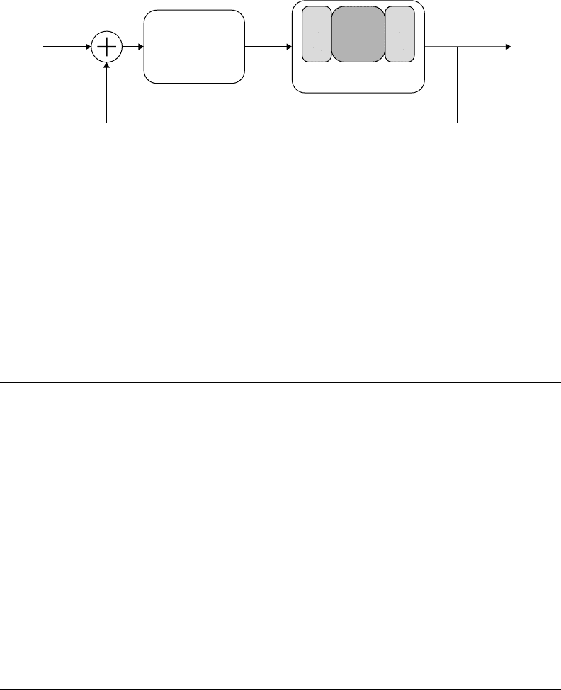
and simulated. Figure 37.2 shows the basic feedback-control loop. The plant, the device to be controlled,
is the upper arm with its motor. The sensor is the position sensor. The controller is the algorithm that
adjusts the motor speed and direction on the basis of the difference between desired and actual position.
Now, consider the entire arm. By controlling the motion of each arm segment about the four joints,
the hand can be moved. This is a multiple-input, multiple-output (MIMO) problem of great interest to
1
It can be acquired through Lynxmotion, www.lynxmotion.com.
37-4 Handbook of Dynamic System Modeling
Input
Controller
System
or
Process
Plant
Sensors
Actuators
Output
FIGURE 37.2 Elements of embedded control systems.
control engineers because many systems have multiple inputs and multiple outputs. Two examples of
this are
•
Washing machines must control water temperature and level, and motor speed based on the type
of clothes and size of the load.
•
Car engines must adjust intake and exhaust levels to meet performance and efficiency requirements.
In general, the use of computational modeling and simulation as described in this chapter has a prolific
application in industry.
37.3 Designing with Simulation
A “design” as used hereafter is defined as a software component or algorithm that functions either alone
or with other components or algorithms. To study the behavior of a new design, a model is needed that
includes not only the design but also other components, systems, or algorithms as well with which the
design interacts. Once a computational model of the entire system is available, simulation can be used to
test and refine the design before going to a final implementation.
Consider the robotic arm. The design is the control algorithm that will be embedded on a microprocessor
connected to the robotic arm. The entire system that must be modeled includes the algorithm, the actual
robot mechanics, electrical circuitry, and any other devices and components that the robot will interact
with. Once this has been modeled accurately, the feedback-control algorithm discussed in the previous
section can be designed. As the algorithm is designed, testing of it in combination with the robot can be
started in a simulation. Since simulated rather than actual hardware is used, it can be quickly experimented
with algorithms as they are developed without costly damage. This would not be possible with a physical
robot because hardware is likely to be damaged during experimentation with different designs. With actual
hardware, a small fleet of robots would be needed to run the same tests.
37.4 Obtaining Computational Models
Here, focus is on the parts of the computational model other than the control algorithm. In the case of
the robotic arm this is the plant, which consists of the actual mechanics, electrical circuitry, and dynamic
effects such as friction. Computational models of physical devices and phenomena can be obtained by one
or more of the following methods (this is not an exhaustive list):
1. Derive mathematical relationships from published or otherwise well-accepted theory, also called
first-principles modeling. To an extent, this area pertains to phenomenological modeling (Broenink,
1990; Karnopp et al., 1990).
2. Derive mathematical relationships using data gathered from the devices being modeled. The data
can then be used in a data-fitting approach (Bendat and Piersol, 2000; Ljung, 1998).
On Simulation of Simulink
®
Models for Model-Based Design 37-5
(b)(a)
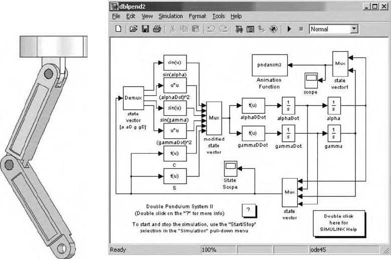
FIGURE 37.3 A pendulum. (a) Multibody model. (b) Simulink model.
3. Use modeling software that derives computational models from physical information such as
mass, inertia, resistance, and capacitance (also considered as first principles). This is more closely
affiliated with structural modeling approaches such as Modelica (Elmqvist et al., 1999; Tiller,
2001).
The first method is typically the most time consuming, but is widely accepted because the engineer has
visual access to the equations that describe the system. The second method relies on techniques such as
curve fitting, fuzzy logic, neural networks, and nonlinear optimizations to produce mathematical estimates
of a systems behavior. While this method can be effective at obtaining models quickly, the engineer must
consider several test scenarios to ensure that the computational models capture all the system dynamics.
The third method is typically the most practical to implement, since the engineer needs to know only
physical properties, not mathematical relationships.
37.4.1 Modeling from First Principles
First-principle modeling methods offer the capability of testing a design through simulation without
committing to specific hardware. This enables development engineers to explore design options more
thoroughly and discover problems early, saving time and money.
Before looking at obtaining the computational model of the robotic arm, consider the double pendulum
in Figure 37.3(a) that is similar to the robotic arm. It contains one less linkage and no turntable. The
kinematics equations could be derived based on first principles (Method 1). The dynamics, however, are
much more difficult to model. The dynamics will require friction models that are difficult to come by,
certainly by derivation from first principles (see, e.g., (Lötstedt, 1981). To do so would require knowledge
much beyond that of multibody dynamics.
37-6 Handbook of Dynamic System Modeling
Bodies Joints Simulink model
Fixture
Link 1
Link 2
Revolute
Joint 1
Revolute
Joint 2
Fixture
Revolute 1
Revolute 2
Link 1
Link 2
CS1CS2
CS1CS2
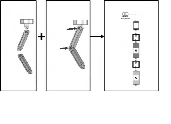
FIGURE 37.4 Elements of a multibody pendulum model.
The following equation represents the kinematics of the double pendulum in Figure 37.3(a):
α =
−L
2
sin (α) + mw
2
(−sin (α −γ)) sin (γ) −ne(−sin (α − γ)) cos (α −γ)α
2
−n cos (α − γ)r
2
1 −ne sin
2
(α −γ)
(37.1)
Note that, in spite of the apparent complexity, Eq. (37.1) does not yet include a friction model. The
corresponding Simulink model for the generalized coordinates is given in Figure 37.3(b). Clearly, the
equations for this relatively simple system can be complex. The more complicated robotic arm will have
an even more complicated formulation.
To further compound matters, where Eq. (37.1) uses a generalized coordinate system with only two
variables, an implementation with Cartesian coordinates would have 12 variables. It is obvious how this
relatively simple device can become very complicated to model and analyze in detail.
The alternative is to use Method 3 for first-principles modeling. The pendulum can be considered a
multirigid-body system that can be modeled in SimMechanics (2006), a modeling tool that works within
Simulink and provides multibody mechanical modeling capabilities. The user only needs information
regarding mass, inertia, dimension, and the position and orientation of joint axes of motion to create a
SimMechanics model. With this information the model compiler can automatically derive the system of
differential and algebraic equations (DAE) that capture the model behavior (Wood and Kennedy, 2003).
Users can assemble bodies and joints to model their systems, or model their systems in SolidWorks
®
(2002) and automatically extract SimMechanics models. Figure 37.4 shows the SimMechanics model
with its one-to-one correspondence to the physical components. This model can then be integrated with
standard Simulink blocks that can be used to model effects such as friction or a control algorithm in
continuous-time, sampled time, or scheduled task form.
Computer Automated Multiparadigm Modeling is increasingly become important to negotiate the
complexity of modern engineered systems (Mosterman and Vangheluwe, 2004). It relies heavily on
domain-specific formalisms and tools. In this vein, tools to model physical systems other than Sim-
Mechanics that generate the mathematical equations from higher-level component representations in
different domains are available to the modeler as well. Simulink integrates tightly with four tools for
component-level first-principles modeling of physical systems (Method 3):
•
SimMechanics models three-dimensional mechanical systems.
•
SimPowerSystems (2006) models electrical circuitry and power flow.

On Simulation of Simulink
®
Models for Model-Based Design 37-7
•
SimDriveline (2006) models one-dimensional rotational motion.
•
SimHydraulics
™
(2006) models hydraulic systems.
These tools can be used in conjunction with equations derived in Simulink to model various types of
systems for a variety of purposes.
37.4.2 Using Data and Simulation to Obtain or Tune Models
Often, one does not have the luxury of using Method 3 exclusively and must use Method 1 to model some
components. Simulink provides an environment where all the tools for modeling physical systems that
are referenced above can be mixed with equations represented with standard Simulink blocks. Methods 1
and 3 assume that the behavior of the system is well-understood. In an ideal world this is true, and one
could model complex behaviors such as friction very accurately. In the real world, however, it must be dealt
with manufacturing tolerances, lack of information about component behavior, and other uncertainties
regarding the systems being modeled. This is where Method 2 is used, which relies on data collected from
the components to either tune existing models built with Methods 1 and 3, or generate linear models
for “black box systems.” As mentioned earlier, there are a variety of data-fitting techniques but the basic
principle is as follows:
•
Apply some disturbance or other input to the system such as moving the double pendulum in
Figure 37.3(b) in a measured way.
•
Measure any change in the system with sensors, this is the system output (here, the pendulum angle
versus time).
•
Use the input/output data pairs to
—tune parameters in existing models, using tools such as Simulink Parameter Estimation
(2006)(considered “gray-box” modeling), or
—generate models using an appropriate tool such as the System Identification Toolbox (2006) or
the Fuzzy Logic Toolbox (2006) (considered black-box modeling).
The black-box techniques such as fuzzy logic are particularly useful in characterizing phenomena
such as chemical processes for which equations might not be easily derived. These modeling methods
can be applied to many systems and processes. Both types of data modeling (gray-box and black-box)
are particularly interesting because they rely on simulation, to tune parameters and generate models,
respectively. In the case of gray-box modeling, Simulink Parameter Estimation simulates a model hundreds
or thousands of times while using optimization techniquesto adapt parameter values until the actual system
output matches the measured system output. This is referred to as parameter tuning as well. In the case
of black-box modeling, the techniques vary slightly depending on the method. The System Identification
Toolbox (2006) enables multiple simulations to generate a model that will give the desired measured
output from the associated input. Once the parameters have been tuned so that the model reflects the
observations of reality accurately, the model can be used in the larger system simulation. Models generated
from data can be incorporated into larger system simulations as well.
Another approach to modeling with data is transfer function estimation. This is the process of tak-
ing experimental data and converting it using spectral estimation techniques to compute the frequency
response of a system (Bendat and Piersol, 2000). The Signal Processing Toolbox (2006) has many functions
that aid in the estimation of a transfer function. Additionally, a linear parametric model can be fit to the
experimental frequency response function using the modeling tools in the System Identification Toolbox.
In some cases, linear models may not describe the model accurately and the underlying equations of
motion may not be that well known. In this case, a nonlinear black-box neural network can be created.
These types of models can be created using the Neural Network Toolbox (2006).
37.5 The Robotic Arm Model
A computational model of the robotic arm is obtained using the different approaches.
37-8 Handbook of Dynamic System Modeling
FIGURE 37.5 CAD model of a robotic arm.
37.5.1 The Mechanical Model of Arm
The computational model of the robotic arm consists of the mechanical model, the motor models, and
the actual controller feedback loop. To model the mechanics, the robot is first modeled with a computer-
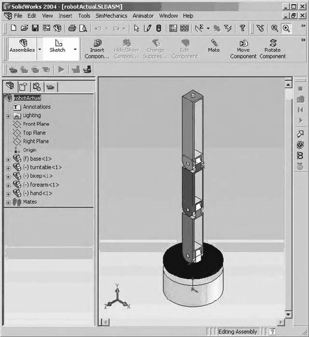
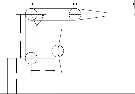
aided design (CAD) tool, in this case SolidWorks (Figure 37.5) using the engineering drawings provided
by the manufacturer (Figure 37.6). The SimMechanics model is then automatically extracted from the
SolidWorks model.
SimMechanics models are composed of bodies connected to each other by joints that have user-specified
ranges of motion. The dimensions of the bodies and the axes of motion for the joints are specified in a
Cartesian coordinate space (x, y, z). The robot in Figure 37.5 has five bodies: three arm segments, the
turntable, and the base. The base is fixed to a reference point, the other dimensions and axes are specified
relative to this ground position. Each body is connected to the adjacent body by a joint as described in
Section 37.2.
37.5.2 Electromechanical Model of the Motor and Coupling
Once the kinematics of the mechanical model are available, the dynamics for the motors and the couplings
that connect the motors to the joints must be modeled. The joints are assumed to be frictionless (which is
a coarse approximation of reality, but sufficient for this application). A pulse-width modulation scheme
On Simulation of Simulink
®
Models for Model-Based Design 37-9
L2
L3
65° max
80°
80°
Typical
0°
L1
L2
L3
H
G
Angle
0
80
80
Pulse
1.50 ms
0.78 ms
2.22 ms
SSC-12
Arm shown
with all axis
aligned to 0°
G
H
L1
3.75"
3.75"
5.00"
3.00"
2.00"
127
37
217
FIGURE 37.6 Engineering drawing of a robotic arm.
regulates the voltage to the electric motor and controls the motion of the linkage. The switching circuitry
is modeled using an H-Bridge, a digital device that can switch the direction of current flow. The motor
itself consists of an inductor, a resistor, and a model of back electromotive force (EMF). The component
blocks for the motor and H-Bridge are from SimPowerSystems. The remaining components in the motor
model are gearing, inertia, and other mechanical components, all modeled in SimDriveline. Since each
joint has one motor, the model can be made a reference to a library component and a separate motor
model connected at each joint. An individual motor model is shown in Figure 37.7. The motor models can
then be coupled to the SimMechanics model of the robotic arm. Standard sensor and actuator interface
blocks are necessary when moving from one modeling formalism to another, such as from SimMechanics
to SimPowerSystems, or to standard Simulink. The blocks translate physical properties such as force and
torque into the time-based signals of Simulink.
37.5.3 Tuning the Motor Parameters with Data
The DC motor model shows a relationship between current and torque. Torque causes the motor shaft to
spin in accordance with a relationship to the back EMF. The remaining parameters include shaft inertia,
viscous friction (damping), armature resistance, and armature inductance. Values for those parameters
must be accurate for the motor model to behave similar to the actual motor. While manufacturers may
provide the values, one should assume those to be averaged values with added manufacturing tolerances.
It is necessary to estimate these parameters as precisely as possible for the model to ascertain whether it
is an accurate representation of the actual DC servo motor system. Table 37.1 lists the model parameters
and their initial values.
When a series of voltage pulses is input to the motor, the motor shaft turns in response. If there is a
discrepancy between the model parameters and those of the physical system, however, the model response
will not match that of the actual system. Figure 37.8 shows the response of the model using the initial
parameter values listed in Table 37.1 together with the actual response of the motor. To obtain a more
accurate response, the parameters must be reestimated. This is where Simulink Parameter Estimation plays
a pivotal role.
