Elsevier Encyclopedia of Geology - vol I A-E
Подождите немного. Документ загружается.

method or methods being proposed. For example,
in the case of electromagnetic and magnetic
methods, signal degradation or geophysical ‘noise’
may be introduced by the presence of surface me-
tallic structures and overhead power lines. For
microgravity or seismic surveys, noise may result
from traffic movements or wind and waves. Where
the level of noise exceeds the amplitude of the
anomaly due to the target and where this cannot
be successfully removed, the target will not be de-
tectable. The best way to assess the likely influence
of site conditions is to visit the site at the design
stage and/or carry out a trial survey.
The design of a survey can be aided by the use of
powerful two-dimensional and three-dimensional
forward-modelling geophysical software. With in-
formation on the expected target size, depth, and com-
position, a geophysicist can evaluate the feasibility
of a particular method, including likely error bars
on modelled size or depth, and can determine opti-
mum survey design parameters such as the sampling
interval and the optimum configuration for the
method (e.g. transmission frequency for ground-
penetrating radar and electromagnetic surveys or the
geophone spacing in a seismic survey).
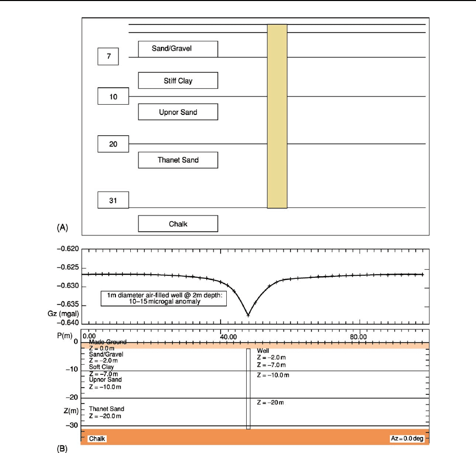
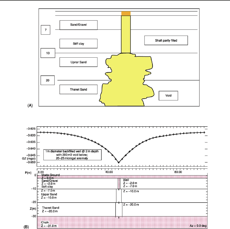
Figures 6 and 7 illustrate the results of a feasibility
study for a tunnelling project in London, UK. Figures
6A and 7A are the client’s conceptual model of a
Victorian well thought to be associated with a risk
of subsidence caused by tunnelling at 20 m depth. The
feasibility analysis facilitated an early appreciation of
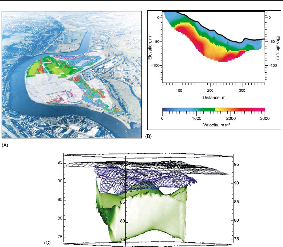
Figure 3 Examples of different display formats. (A) Plot of residual magnetics data showing ferrous targets, draped on an
aerial photograph of the 80 ha brownfield site. (B) Modelled seismic velocity cross-section for proposed pipeline route. (C) Three-
dimensional visualization of the geometry of the base of a landfill cell (green) and the top of leachate (blue mesh) derived from a
combined two-dimensional resistivity imaging and time-domain electromagnetic survey.
486 ENGINEERING GEOLOGY/Geophysics
the limitations of the selected methodology and en-
abled a go/no-go decision to be made on carrying out
a full-scale geophysical survey.
Working closely with the engineer, a geophysical
advisor can clarify the likely value of using geophysics
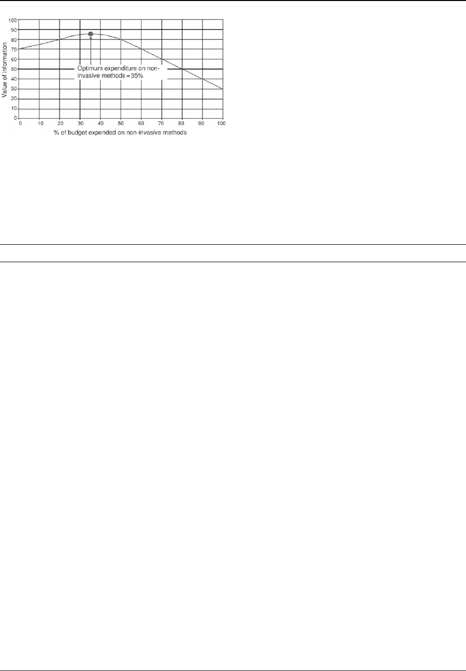
in a site investigation. Assuming that geophysics is
viable for solving a particular problem, then the next
step is to help the client decide what combination of
geophysical screening and direct sampling would give
the optimum information on the subsurface for the
budget available (Figure 8).
Applications
Common applications of engineering geophysics can
be broadly separated into seven main classes, each of
which encompasses a range of different target types:
1. transport infrastructure – the application of geo-
physics in the design and monitoring of structures
such as roads, railways, bridges, tunnels, and
canals;
2. foundation design – the measurement of the engin-
eering properties of soils and bedrock, for example
in determining the depth to a pile-bearing layer;
3. pipeline route evaluation – the selection of appro-
priate route and design criteria, for example meas-
uring soil corrosivity for cathodic protection;
4. hazards identification – the identification and
monitoring of natural hazards such as cavities
and landslides and man-made structures including
mineshafts and unexploded ordnance;
5. non-destructive testing of structures;
6. containment structures – integrity testing and
monitoring of structures such as dams and land-
fills; and
7. buried assets – mapping the location of utilities
and underground storage tanks.
Targets tend to be either isolated structures – such
as a mineshaft, tunnel, foundations, or underground
tank – or laterally extensive – such as bedrock layers,
overburden, or groundwater. Table 3 presents some
examples of the use of geophysics to solve common
engineering problems.
Transport Infrastructure
Geophysical methods have a valuable role to play
in both the design and monitoring of linear en-
gineering structures, such as roads, railways, and
canals, and related structures, such as bridges and
tunnels.
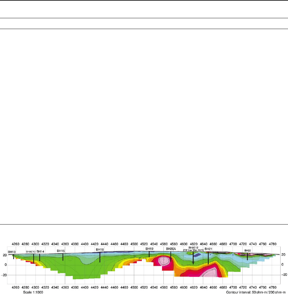
The near-continuous lateral coverage afforded by a
technique such as continuous-wave electromagnetic
profiling is particularly useful during route selection,
as it provides a rapid and cost-effective means of
assessing near-surface ground conditions. Reconnais-
sance surveys of this type may be followed up by more
detailed studies using quantitative techniques such
as seismic refraction profiling and two-dimensional
resistivity imaging within areas identified as being
of particular risk or that display anomalous ground
conditions (Figure 9).
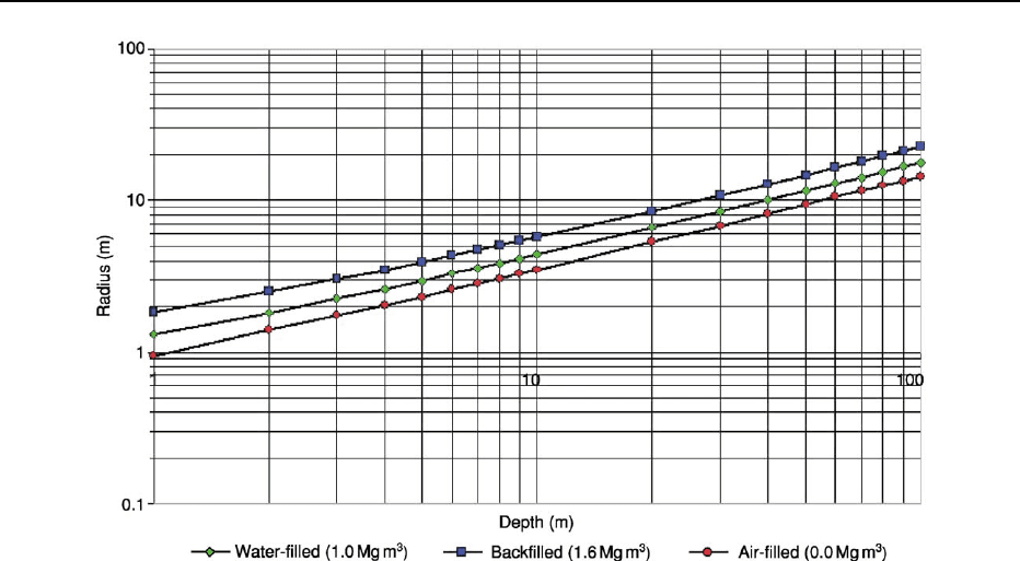
Figure 4 Approximate minimum radius of cavity that will produce a 15 mgal microgravity anomaly in host rock of density 2.3 Mg/m
3
.
ENGINEERING GEOLOGY/Geophysics 487
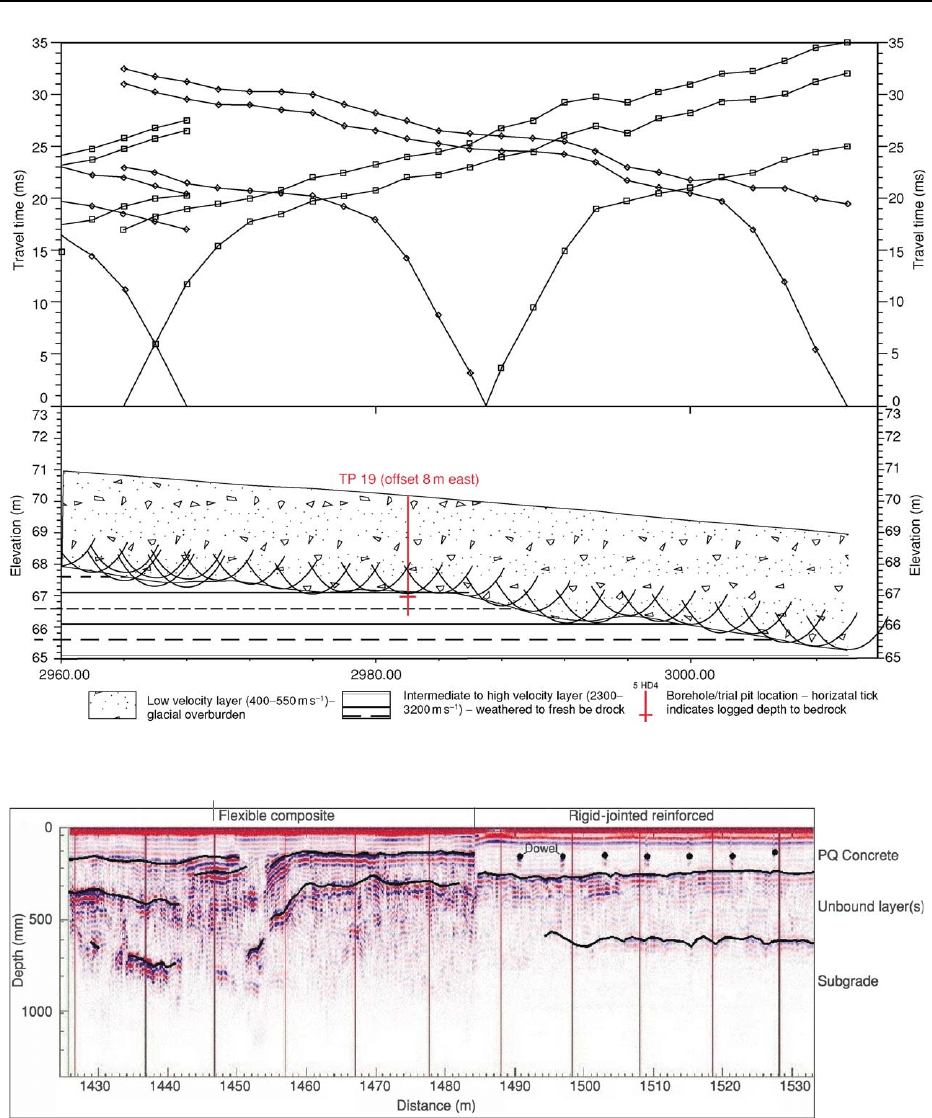
The main application of seismic refraction profiling
is in the determination of bedrock depth and depth
to groundwater (Figure 10). However, analysis of the
P-wave velocity values obtained during such surveys
can also be employed to map the variability in the
strength of the bedrock along a route. The evaluation
of so-called bedrock rippability is particularly useful
in areas where excess material may need to be re-
moved, such as in cuttings and the formation of em-
bankments, in helping to determine the type of plant
that will be required.
The heavy weight of traffic on roads and railways
means that monitoring the condition of road pave-
ments and track ballast is essential for proactive
maintenance and planning of renewals. Ground pene-
trating radar (GPR) is particularly suited to this
task. Modern digital GPR acquisition systems enable
detailed mapping of changes in road-pavement con-
struction, layer thicknesses, and ballast thickness
and condition at speeds in excess of 100 km h
1
(Figure 11).
GPR can also play an important role in the evalu-
ation of structures such as bridges and tunnels. Com-
mon applications include the identification of voiding
behind brick or concrete tunnel linings and mapping
the location and condition of bridge-deck reinforcing.
In order to determine layer thicknesses accurately
the velocity of the GPR signal within the materials
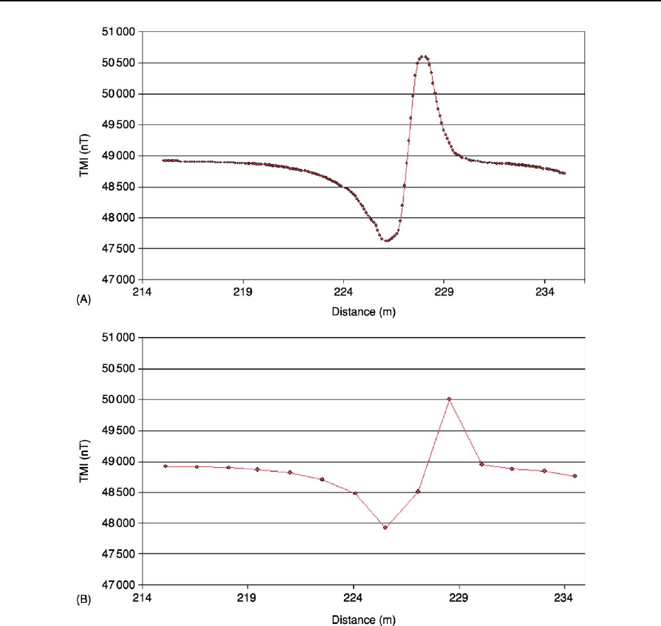
Figure 5 Example of the effects of aliasing on the detection of a pipe using magnetic profiling. The profile shown in Figure 5A
illustrates correct sampling of the anomaly, whilst the profile shown in Figure 5B illustrates the smoothing effects of under-sampling.
488 ENGINEERING GEOLOGY/Geophysics
overlying an interface needs to be determined. This
is normally done directly through the use of core
samples but can also be derived indirectly using
geometric techniques such as curve-fitting on hyper-
bolic anomalies and common mid-point analysis. The
effective use of core samples requires that the data be
accurately located.
Foundation Design
Geophysical methods are routinely used to measure
the engineering properties of soils and bedrock as an
input to the design of foundation structures including
piles. These properties include but are not limited
to soil resistivity, shear modulus, Poisson’s ratio, and
percentage moisture content. These properties are
usually derived from measurements taken from
the surface or from boreholes. Methods for deriving
low-strain elastic moduli include surface-wave seis-
mics, seismic refraction, cross-hole seismics, seismic
tomography (Figure 2), and sonic logging.
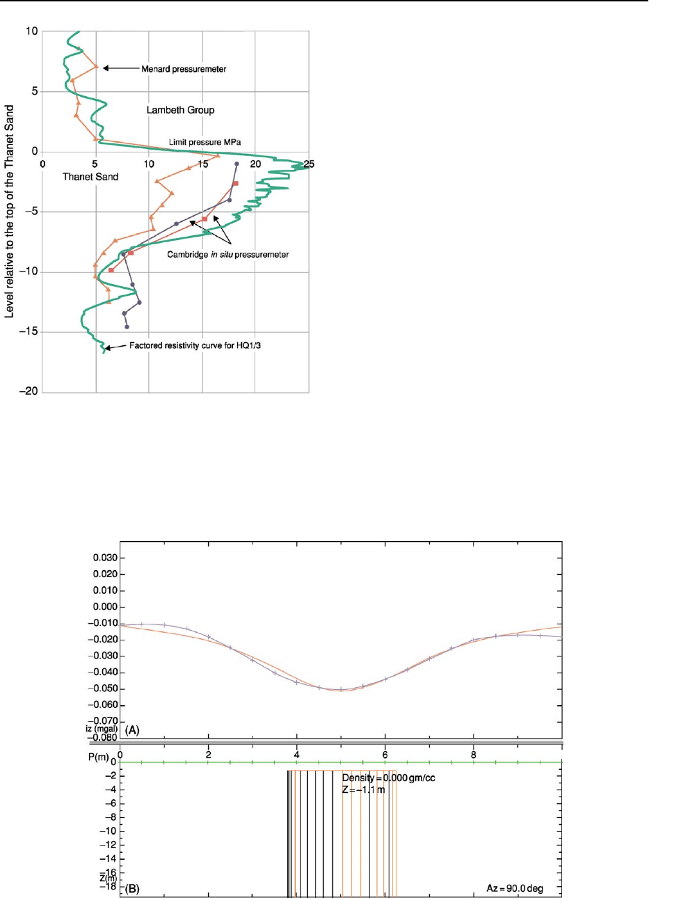
Wireline logging has been used to correlate
stratigraphy between boreholes and provide a clearer
definition of stratal boundaries and type. In the
Figure 6 (B) The use of two-dimensional forward modelling to determine the feasibility of using the microgravity method to detect
(A) Victorian water wells. The size of the anomaly is 10 mGals, which, in the conditions prevalent on site (busy streets in London), would
have been below the resolution of modern digital microgravity meters.
ENGINEERING GEOLOGY/Geophysics 489
example shown in Figure 12, taken from a log from
the Isle of Dogs in London, UK, the electrical log
demonstrated a difference between the upper and
lower parts of the Thanet Sand that was not obvious
when looking at standard soils data such as
gradings. The electrical log was matched to measure-
ments of limit pressure in pressuremeter tests, and as
a lower bound to SPT (Standard Penetration Test)
data. The geophysical tool proved to be a power-
ful and cost-effective alternative for delineating the
pile-bearing horizon in the Thanet Sand.
Pipeline Investigations
Determination of the most suitable route for a
pipeline and the type of materials or protective
measures required to prevent its corrosion in the
ground can both be aided by the use of geophysical
techniques.
As in the case of other linear structures such as
roads, route evaluation may require the determin-
ation of bedrock depth, mapping of lateral variations
in the nature of overburden materials, and the
Figure 7 (B) The use of two-dimensional forward modelling to determine the feasibility of using the microgravity method to detect
(A) collapse structures associated with Victorian water wells. The size of the anomaly is 25 mGals, which is readily detectable using
modern digital microgravity meters.
490 ENGINEERING GEOLOGY/Geophysics
location of subsurface hazards or anomalous ground
conditions that may affect the construction or long-
term integrity of the structure. Methods commonly
employed include seismic refraction and electrical
resistivity imaging for profiling bedrock depth, to-
gether with resistivity soundings and electromagnetic
profiling for overburden characterization. The linear
nature of pipelines means that they often traverse a
diverse range of terrains, and, consequently, the type
of hazard that may be encountered will be varied and
not always obvious. Figure 13 illustrates data from a
detailed microgravity survey undertaken along the
proposed route of a pipeline in the UK with the ob-
jective of locating buried mineshafts. Forward and
inverse modelling of the data allowed the likely size
and depth of the shaft to be determined.
Figure 8 Example of a cost–benefit analysis to determine the
highest-value spend (i.e. most information derived) for a fixed
site-investigation budget; in this brownfield case 35% of the
budget was allocated for site-wide geophysical screening, to
target trial pits and boreholes that might otherwise miss important
features.
Table 3 Examples of the application of geophysical methods in engineering investigations
Application Example Typical methods
Transport infrastructure
Route evaluation Determination of thickness
of overburden
Seismic refraction, 2D resistivity imaging depending on nature of
expected lithologies and water table
Location of buried channel Seismic refraction or 2D resistivity imaging for large-scale structures
Identification of karstic
structures (swallow
holes, cavities)
Continuous-wave electromagnetic profiling (reconnaissance),
microgravity and seismic refraction for detailed modelling
Pavement/ballast
assessment
Measurement of thickness
of pavement or track
layers and mapping
location of construction or
condition changes
High-speed GPR (200–1200 MHz)
Structural assessment Mapping location, depth,
and condition of
reinforcing within
concrete
High-frequency (900–1500 MHz) GPR, continuous-wave
electromagnetic profiling
Identification of voiding,
moisture retention behind
tunnel wall lining
High-frequency (900–1200 MHz) GPR, infrared thermography
Foundation design
Stratigraphic Determination of depth to
pile-bearing layer
Seismic refraction/reflection, cross-hole seismics, seismic
tomography, surface-wave seismics, wireline geophysics
Mapping boundaries of
layers
Seismic refraction, seismic reflection, cross-hole seismics, seismic
tomography, surface-wave seismics, wireline geophysics
Measuring the stiffness of
soils
Seismic refraction, seismic reflection, P- and S-wave cross-hole,
up-hole, and down-hole seismics, cross-hole seismic tomography,
surface-wave seismics, wireline geophysics
Rock rippability Seismic refraction
Groundwater table Seismic refraction, 2D resistivity imaging, time-domain electro-
magnetic sounding, 1D resistivity soundings, wireline logging
Structural Mapping fault zones Very-low-frequency continuous-wave electromagnetic profiling,
seismic reflection
Pipeline route evaluation
Route evaluation –
geological
Determination of thickness
of overburden
Seismic refraction, seismic reflection (P- and S-wave), 2D resistivity
imaging, microgravity, continuous-wave electromagnetic, time-
domain electromagnetic sounding
Rock rippability Seismic refraction
Corrosivity of soils Resistivity, continuous-wave electromagnetic, redox potential
Continued
ENGINEERING GEOLOGY/Geophysics 491
The prevention of corrosion of buried pipelines
requires knowledge of the aggressivity of the soils
along the proposed route. A soil’s aggressiveness
depends on three main factors: its pH, redox poten-
tial, and electrical conductivity. Once these factors
have been determined suitable preventative measures
can be put in place. These can include cathodic pro-
tection, zinc coating, or the use of plastic rather than
steel pipes.
The soil electrical conductivity (or resistivity) might
be determined at selected positions along the route
using techniques such as one-dimensional resistivity
or time-domain electromagnetic sounding or in a
more continuous manner using methods such as elec-
tromagnetic profiling and capacitively coupled towed
resistivity imaging.
Resistivity soundings have the advantage of provid-
ing a profile of the variation in soil resistivity with
depth, thereby enabling aggressive layers within the
soil to be avoided by altering the depth of the pipe.
However, as with other point-sampling investigation
tools such as boreholes, areas of importance along a
Archaeological assessment Map anthropogenic features
such as buried pits, walls,
foundations, crypts
Magnetics, resistivity profiling, GPR, 2D resistivity imaging, magnetic
susceptibility
Hazards identification See below See below
Hazards identification
Geological Natural cavities and
sinkholes
Microgravity, GPR, 2D resistivity imaging, continuous wave
electromagnetic
Brownfield and current
industrial
In-ground obstructions Continuous-wave electromagnetic, magnetics, time-domain
electromagnetic, GPR, microgravity
Mineshafts Microgravity, continuous-wave electromagnetic, magnetics, 2D
resistivity imaging, GPR, infrared thermography
Detection of live cables Passive electromagnetic
Detection of unexploded
ordnance
Magnetics, time-domain electromagnetic, GPR
Mapping contaminant
sources and pathways
Continuous-wave electromagnetic, 2D resistivity imaging, spectral
induced polarization, self potential, GPR, microgravity
Mapping existence and
number of underground
storage tanks
Continuous-wave electromagnetic, magnetics, time-domain
electromagnetic, GPR, microgravity
Containment structures
Construction Quality control of
construction process
Electric leak location, GPR, resistivity imaging
Integrity of engineered
structure over time
Self potential, 2D/3D resistivity imaging, continuous-wave
electromagnetic, GPR, borehole geophysics
Buried assets
Utilities Verifying existing maps and
producing 3D plans
Passive electromagnetic, continuous-wave electromagnetic,
magnetics, time-domain electromagnetic, GPR
Underground storage tanks Pre-purchase audit Magnetics and/or time-domain electromagnetic, GPR, microgravity
(for non-metallic tanks)
Table 3 Continued
Application Example Typical methods
Figure 9 Cross-section illustrating the results of a two-dimensional resistivity imaging survey along a proposed road route in
southern Ireland. The objective of the survey was to determine the thickness of the glacial overburden overlying the limestone
bedrock. Areas of high resistivity, relating to the bedrock, appear orange and red, whilst areas of lower resistivity, due to the overlying
glacial deposits, appear green and blue. The deep area of overburden on the left of the image relates to infilling of a solution feature.
492 ENGINEERING GEOLOGY/Geophysics
route may be missed. Techniques such as continuous
wave electromagnetic profiling enable more continu-
ous coverage but require multiple passes with differ-
ent instrument configurations to determine variations
in resistivity with depth. As with other route investi-
gations, it is often beneficial to undertake an initial
reconnaissance survey using a profiling method and
then target areas of interest with soundings.
Hazard Identification
Knowledge of potential subsurface hazards is
critical to the safe development and maintenance of
Figure 10 Seismic refraction survey to map depth to bedrock along a proposed road route.
Figure 11 GPR pavement survey, illustrating two types of pavement construction.
ENGINEERING GEOLOGY/Geophysics 493
an engineering structure. A lack of information on
the location and nature of both natural and man-
made hazards, such as caves, mineshafts, buried land-
fills, and unexploded ordnance, could potentially be
catastrophic and could lead to costly delays.
p0205An example of how geophysics can be used to
mitigate the risk posed by natural sinkholes is illus-
trated in Figure 14. A previous site investigation,
incorporating four boreholes located one in each
corner of the site, had determined that the depth to
chalk bedrock and the condition of the chalk were
essentially similar in each borehole. The regulator
was informed and permission was given to construct
the landfill cell. Not long after commencement, the
earthworks contractor encountered large sinkhole
features in the chalk, and the works were halted.
The regulator requested that a geophysical survey be
carried out to clarify the extent of the problem. A
ground-conductivity map of the 1 ha area highlighted
numerous sinkhole features as ground-conductivity
highs. These features were then further investigated
using resistivity imaging and cone penetrometer
testing to determine the depth of the sinkholes.
A hypothetical exercise was carried out to determine
how many boreholes would have been required to
match the detail provided by the geophysical survey.
Figure 12 Comparison of geophysical (resistivity in green) and
geotechnical (Menard pressuremeter and Cambridge in situ pres-
suremeter) results for a borehole in London, UK. (Published with
permission of Arup 2003.)
Figure 13 Modelling the microgravity response of a buried mineshaft. (A) The blue line represents the observed gravity data, whilst
the red line represents the calculated response due to (B) a cylindrical source body.
494 ENGINEERING GEOLOGY/Geophysics
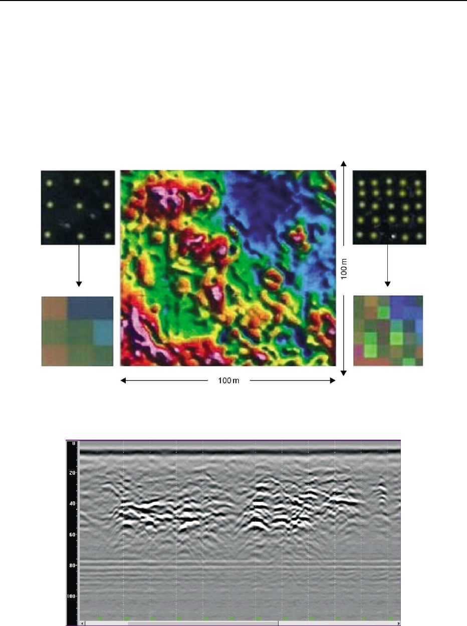
Figure 14 shows that for a three-by-three (total of
nine) or even a five-by-five (total of 25) grid of bore-
holes the information on the extent of sinkhole devel-
opment would have been patchy at best. The most
cost-effective sequence of events would have been to
carry out the ground-conductivity survey first and
then drill three or four boreholes in targeted areas
that were revealed by geophysics to be representative
of background and anomalies. Figure 15 presents an
example of the use of ground penetrating radar to
locate potentially hazardous voids within karstic
limestone. The high resolution obtained from GPR
surveys is ideal for the detection of small-scale near-
surface cavities but under good conditions, such as in
unweathered hard rock, the technique is also capable
of providing information to significant depth. In these
circumstances it is often used to complement data
obtained from more traditional techniques such as
microgravity profiling.
Projects on land associated with, or affected by,
military activities may have an increased risk of en-
countering unexploded ordnance. Examples include
Figure 14 Comparison of the results of undertaking an electromagnetic (apparent conductivity) survey (centre) across a site to map
solution features in chalk and a more traditional site-investigation approach using just boreholes (left and right). Red and magenta areas
on the apparent-conductivity map represent sinkholes filled with moist sand. The blue and green areas correspond to competent chalk.
Figure 15 The use of GPR to locate voiding within karstic limestone for a port development in the Dominican Republic. The areas of
white and black on this B-scan plot (or ‘radargram’) are indicative of clustered small-scale (less than 0.5 m in diameter) voids within
otherwise competent limestone. The vertical axis on the plot represents the two-way travel time of the GPR signal through the rock
measured in nanoseconds.
ENGINEERING GEOLOGY/Geophysics 495
