El-Hawary M.E. Electrical Energy Systems
Подождите немного. Документ загружается.

204
© 2000 CRC Press LLC
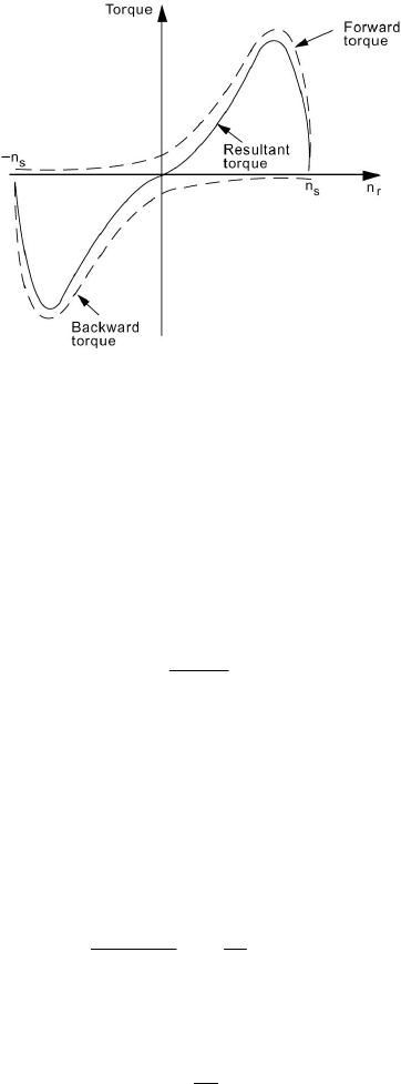
single-phase induction motor is therefore incapable of producing a torque at rest
and is not a self-starting machine. If the rotor is made to rotate by an external
means, each of the two fields would produce a torque-speed characteristic
similar to a balanced three-phase (or two-phase) induction motor, as shown in
Figure 6.11 in the dashed curves. The resultant torque-speed characteristic is
shown in a solid line. The foregoing argument will be confirmed once we
develop an equivalent circuit for the single-phase induction motor.
6.6 EQUIVALENT CIRCUITS FOR SINGLE-PHASE INDUCTION
MOTORS
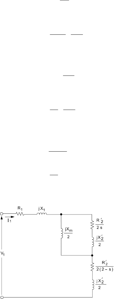
In a single-phase induction motor, the pulsating flux wave resulting
from a single winding stator MMF is equal to the sum of two rotating flux
components. The first component is referred to as the forward field and has a
constant amplitude equal to half of that of the stator waveform. The forward
field rotates at synchronous speed. The second component, referred to as the
backward field, is of the same constant amplitude but rotates in the opposite (or
backward) direction at synchronous speed. Each component induces its own
rotor current and creates induction motor action in the same manner as in a
balanced three-phase induction motor. It is on this basis that we conceive of the
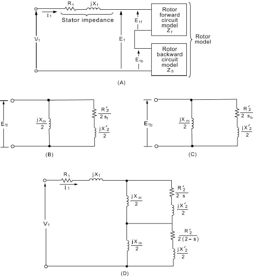
circuit model of Figure 6.12(A).NotethatR
1
and X
1
are the stator resistance
and leakage reactance, respectively, and V
1
is the stator input voltage. The EMF
E
1
is assumed to be the sum of two components,
f
E
1
and
b
E
1
, corresponding to
the forward and backward field waves, respectively. Note that since the two
waves have the same amplitude, we have
2
1
11
E
EE
bf
== (6.25)
The rotor circuit is modeled as the two blocks shown in Figure 6.12(A),
representing the rotor forward circuit model Z
f
and the rotor backward circuit
model Z
b
, respectively.
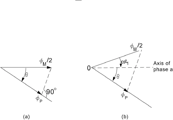
Figure 6.10 Showing that
φ
b
is a backward-rotating wave: (A) t = 0; (B) t = t
1
.
205
© 2000 CRC Press LLC
Figure 6.11 Torque-speed characteristics of a single-phase induction motor.
The model of the rotor circuit for the forward rotating wave Z
f
is simple
since we are essentially dealing with induction-motor action and the rotor is set
in motion in the same direction as the stator synchronous speed. The model of
Z
f
is shown in Figure 6.12(B) and is similar to that of the rotor of a balanced
three-phase induction motor. The impedances dealt with are half of the actual
values to account for the division of E
1
into two equal voltages. In this model,
X
m
is the magnetizing reactance, and
2
R
′
and
2
X
′
are rotor resistance and
leakage reactance, both referring to the stator side. The slip s
f
is given by
s
rs
f
n
nn
s
−
=
(6.26)
This is the standard definition of slip as the rotor is revolving in the same
direction as that of the forward flux wave.
The model of the rotor circuit for the backward-rotating wave Z
b
is
shown in Figure 6.12(C) and is similar to that of Z
f
, with the exception of the
backward slip, denoted by s
b
. The backward wave is rotating at a speed of –n
s
,
and the rotor is rotating at n
r
. We thus have
s
r
s
rs
b
n
n
n
nn
s
+=
−
−−
=
1
)(
(6.27)
Using Eq. (6.26), we have
s
r
f
s
n
n
1
−=
(6.28)
As a result, we conclude that the slip of the rotor with respect to the backward
206
© 2000 CRC Press LLC
wave is related to its slip with respect to the forward wave by
fb
ss
−=
2
(6.29)
We now let s be the forward slip,
ss
f
=
(6.30)
and thus
ss
b
−=
2
(6.31)
On the basis of Eqs. (6.30) and (6.31), a complete equivalent circuit as shown in
Figure 6.12(D) is now available. The core losses in the present model are
treated separately in the same manner as the rotational losses.
Figure 6.12 Developing an equivalent circuit of for single-phase induction motors: (A) basic
concept; (B) forward model; (C) backward model; and (D) complete equivalent circuit.
207
© 2000 CRC Press LLC
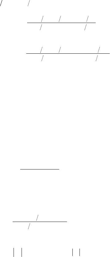
The forward impedance Z
f
is obtained as the parallel combination of
(jX
m
/2) and )]2()2[(
22
sXjsR
′
+
′
, given by
]2)[()2(
)]2()2)[(2(
22
22
XXjsR
XjsRXj
Z
m
m
f
′
++
′
′
+
′
=
(6.32)
Similarly, for the backward impedance, we get
]2)[()2(2[
)]}2()]2(2){[2(
22
22
XXjsR
XjsRXj
Z
m
m
b
′
++−
′
′
+−
′
=
(6.33)
Note that with the rotor at rest, n
r
= 0, and thus with s = 1, we get Z
f
= Z
b
.
Example 6.5
The following parameters are available for a 60-Hz four-pole single-phase 110-
V ½-hp induction motor:
R
1
= 1.5
Ω
2
R
′
= 3
Ω
X
1
= 2.4
Ω
2
X
′
= 2.4
Ω
X
m
= 73.4
Ω
Calculate Z
f
, Z
b
, and the input impedance of the motor at a slip of 0.05.
Solution
Ω+=
∠=
+
+
=
851.14294.17
654.40796.22
9.3730
)2.130(7.36
j
j
jj
Z
f
$
The result above is a direct application of Eq. (6.32). Similarly, using Eq.
(6.33), we get
Ω+=
Ω∠=
+
+
=
766.1721.0
502.5838.1
9.37)95.15.1(
]2.1)95.15.1[(7.36
j
j
jj
Z
b
$
We observe here that
f
Z is much larger than
b
Z
at this slip, in contrast to the
situation at starting (s = 1), for which Z
f
= Z
b
.
The input impedance Z
i
is obtained as
Ω∠=
+=++=
36.43841.26
428.18515.19
1
$
jZZZZ
bfi
Equations (6.32) and (6.33) yield the forward and backward

208
© 2000 CRC Press LLC
impedances on the basis of complex number arithmetic. The results can be
written in the rectangular forms
fff
jXRZ
+=
(6.34)
and
bbb
jXRZ
+=
(6.35)
Using Eq. (6.32), we can write
22
2
2
tf
mf
f
Xa
Xa
R
+
=
(6.36)
and
)(
2
2
XXa
Xa
R
X
tf
mf
f
f
′
+=
(6.37)
where
s
R
a
f
2
′
=
(6.38)
mt
XXX
+
′
=
2
(6.39)
In a similar manner we have, using Eq. (6.33),
22
2
2
tb
mb
b
Xa
Xa
R
+
=
(6.40)
)(
2
2
XXa
Xa
R
X
tb
mb
b
b
′
+=
(6.41)
where
s
R
a
b
−
′
=
2
2
(6.42)
It is often desirable to introduce some approximations in the formulas
just derived. As is the usual case, for X
t
> 10 a
b
, we can write an approximation
to Eq. (6.40) as
209
© 2000 CRC Press LLC
2
2
≅
t
m
bb
X
X
aR
(6.43)
As a result, by substitution in Eq. (6.41), we get
m
bb
t
m
b
X
Ra
X
XX
X
+
′
≅
2
2
(6.44)
We can introduce further simplifications by assuming that X
m
/X
t
≅
1, to
obtain from Eq. (6.43)
s
R
aR
bb
−
′
=≅
2
2
2
(6.45)
Equation (6.44) reduces to the approximate form
m
b
b
X
X
X
2
a
2
2
2
+
′
≅ (6.46)
Neglecting the second term in Eq. (6.46), we obtain the most simplified
representation of the backward impedance as
)2(2
2
s
R
R
b
−
′
=
(6.47)
2
2
X
X
b
′
=
(6.48)
Equations (6.47) and (6.48) imply that X
m
/2 is considered an open circuit in the
backward field circuit, as shown in Figure 6.13.
Figure 6.13 Approximate equivalent circuit of a single-phase induction motor.

210
© 2000 CRC Press LLC
6.7 POWER AND TORQUE RELATIONS
The development of an equivalent-circuit model of a running single-
phase induction motor enables us to quantify power and torque relations in a
simple way. The power input to the stator P
i
is given by
111
cos
φ
IVP
i
= (6.49)
where
φ
1
is the phase angle between V
1
and I
1
. Part of this power will be
dissipated in stator ohmic losses,
s
P
"
, given by
1
2
1
RIP
s
=
"
(6.50)
The core losses will be accounted for as a fixed loss and is treated in the same
manner as the rotational losses at the end of the analysis. The air-gap power P
g
is thus given by
s
ig
PPP
"
−= (6.51)
The air-gap power is the power input to the rotor circuit and can be
visualized to be made up of two components. The first component is the power
taken up by the forward field and is denoted by P
gf
, and the second is the
backward field power denoted by P
gb
. Thus we have
gbgfg
PPP
+=
(6.52)
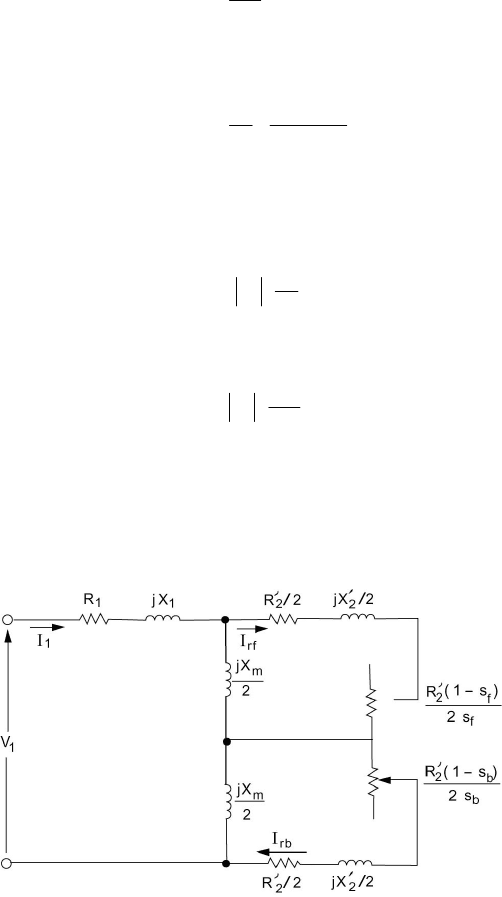
As we have modeled the forward field circuit by an impedance Z
f
, it is natural to
write
fgf
RIP
2
1
= (6.53)
Similarly, we write
bgb
RIP
2
1
= (6.54)
The ohmic losses in the rotor circuit are treated in a similar manner.
The losses in the rotor circuit due to the forward field
rf
P
"
can be written as
gff
rf
PsP
=
"
(6.55)
Similarly, the losses in the rotor circuit due to the backward field are written as
gbb
rb
PsP
=
"
(6.56)
211
© 2000 CRC Press LLC
Equations (6.55) and (6.56) are based on arguments similar to those used with
the balanced three-phase induction motor. Specifically, the total rotor equivalent
resistance in the forward circuit is given by
f
rf
s
R
R
2
2
′
=
(6.57)
This is written as
f
f
rf
s
sR
R
R
2
)1(
2
2
2
−
′
+
′
=
(6.58)
The first term corresponds to the rotor ohmic loss due to the forward field and
the second represents the power to mechanical load and fixed losses. It is clear
from Figure 6.14 that
2
2
2
R
IP
rf
rf
′
=
"
(6.59)
and
f
rfgf
s
R
IP
2
2
2
′
=
(6.60)
Combining Eqs. (6.59) and (6.60), we get Eq. (6.55). A similar argument leads
to Eq. (6.56). It is noted here that Eqs. (6.53) and (6.60) are equivalent, since
the active power to the rotor circuit is consumed only in the right-hand branch,
with jX
m
/2 being a reactive element.
Figure 6.14 Equivalent circuit of single-phase induction motor showing rotor loss components in
the forward and backward circuits.
212
© 2000 CRC Press LLC
The net power form the rotor circuit is denoted by P
m
and is given by
mbmfm
PPP
+=
(6.61)
The component P
mf
is due to the forward circuit and is given by
rf
gfmf
PPP
"
−=
(6.62)
Using Eq. (6.55), we get
gffmf
PsP )1(
−=
(6.63)
Similarly, P
mb
is due to the backward circuit and is given by
rb
gbmb
PPP
"
−= (6.64)
Using Eq. (6.56), we get
gbbmb
PsP )1(
−=
(6.65)
Recall that
ss
ss
b
f
−=
=
2
As a result,
gfmf
PsP )1(
−=
(6.66)
gbmb
PsP )1(
−=
(6.67)
We now substitute Eqs. (6.66) and (6.67) into Eq. (6.61), to obtain
))(1(
gbgfm
PPsP
−−=
(6.68)
The shaft power output P
o
can now be written as
corerot
PPPP
mo
−−= (6.69)
The rotational losses are denoted by P
rot
and the core losses are denoted by P
core
.
The output torque T
o
is obtained as

213
© 2000 CRC Press LLC
r
o
o
P
T
ω
= (6.70)
If fixed losses are neglected, then
)1( s
P
T
s
m
m
−
=
ω
(6.71)
As a result, using Eq. (6.68), we get
)(
1
gbgf
s
m
PPT
−=
ω
(6.72)
The torque due to the forward field is
s
gf
r
mf
mf
PP
T
ωω
== (6.73)
The torque due to the backward field is
s
gb
r
mb
mb
P
P
T
ωω
−== (6.74)
It is thus clear that the net mechanical torque is the algebraic sum of a forward
torque T
mf
(positive) and a backward torque T
mb
(negative). Note that at starting,
s = 1 and R
f
= R
b
, and as a result P
gf
= P
gb
, giving zero output torque. This
confirms our earlier statements about the need for starting mechanisms for a
single-phase induction motor. This is discussed in the next section.
Example 6.6
For the single-phase induction motor of Example 6.5, it is necessary to find the
power and torque output and the efficiency when running at a slip of 5 percent.
Neglect core and rotational losses.
Solution
In Example 6.5 we obtained
$
36.43841.26
∠=
i
Z
As a result, with V
1
= 0110
∠
, we obtain
A36.43098.4
36.43841.26
0110
1
$
$
−∠=
∠
∠
=
I
