Duan C.G., Karelin V.Y. Abrasive Erosion and Corrosion of Hydraulic machinery
Подождите немного. Документ загружается.


184
Abrasive Erosion and Corrosion of Hydraulic Machinery
I
e
a
o
O
2 fcr
I
£^
-
A '\^ i-
^"\"
—
^ -_
J
" —---.
-fl
A.<0.5
X=l
A.=2.3
A.=5
X>%
20 60
100
Sand content S (kg/m )
Figure 4.19 Effects of sand content S on K
m
for different length "k
Sand from Yellow River
\
d50=0.014-0.018mm
J i I L^jb
0 10 20 30 40 50 60 70 80 90
.3-.
Sand content S(kg/m )
Figure 4.20 Relation between sand content S and cavity length

Design of Hydraulic Machinery Working in Sand Laden Water 185
35
g 25
0
<2
15
'o
n
O ^
o
10 15 20
Sand content S(kg/m
3
)
25 30
Figure 4.21 Relation between sand content and cavity length for
NACA 4412 (d
50
= 0.165 mm, P
s
= 1070 kg/m
3
, a = 4°)
100
Sand content S(kg/m )
Figure 4.22 Relation between sand contents and relative fluctuate cavity
length (NACA4412, a= 4°, d
50
= 0.165 mm, P
s
= 1070 kg/m
3
)
186 Abrasive Erosion and Corrosion of Hydraulic Machinery
4.2.2 Model Experiments on Cavitation of Turbines in Silt-Laden
Flow
Results of two test of model turbines conducted in closed circuit test stands
with silt-laden flow have been reported (Huang S.H., 1994)
[4.3].
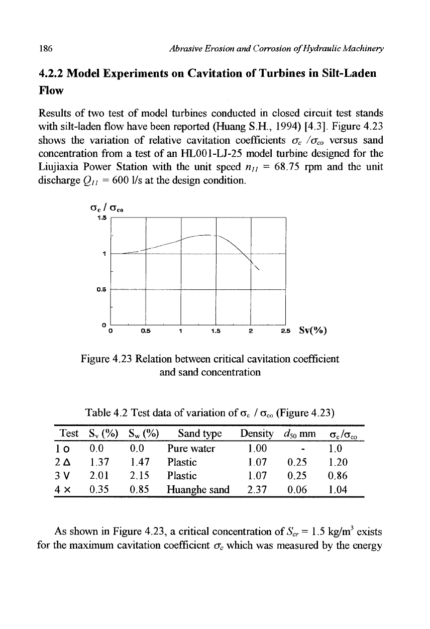
Figure 4.23
shows the variation of relative cavitation coefficients a
c
/a
co
versus sand
concentration from a test of an HL001-LJ-25 model turbine designed for the
Liujiaxia Power Station with the unit speed n
u
= 68.75 rpm and the unit
discharge Qu = 600 1/s at the design condition.
a
c
I a
co
1.5
1
0.5
O
O 0.5 1 1.5 2 2.5 Sv(%)
Figure 4.23 Relation between critical cavitation coefficient
and sand concentration
Table 4.2 Test data of variation of a
0
I a
m
(Figure 4.23)
Test
10
2A
3 V
4x
S
v
(%)
0.0
1.37
2.01
0.35
S
w
(%)
0.0
1.47
2.15
0.85
Sand type
Pure water
Plastic
Plastic
Huanghe sand
Density
1.00
1.07
1.07
2.37
4 mm
-
0.25
0.25
0.06
cr
c
/cr
co
1.0
1.20
0.86
1.04
As shown in Figure 4.23, a critical concentration of S
cr
=
1.5 kg/m
3
exists
for the maximum cavitation coefficient a
c
which was measured by the energy
-
-
-
„—
x
\
\
Design of Hydraulic Machinery Working in Sand Laden Water
187
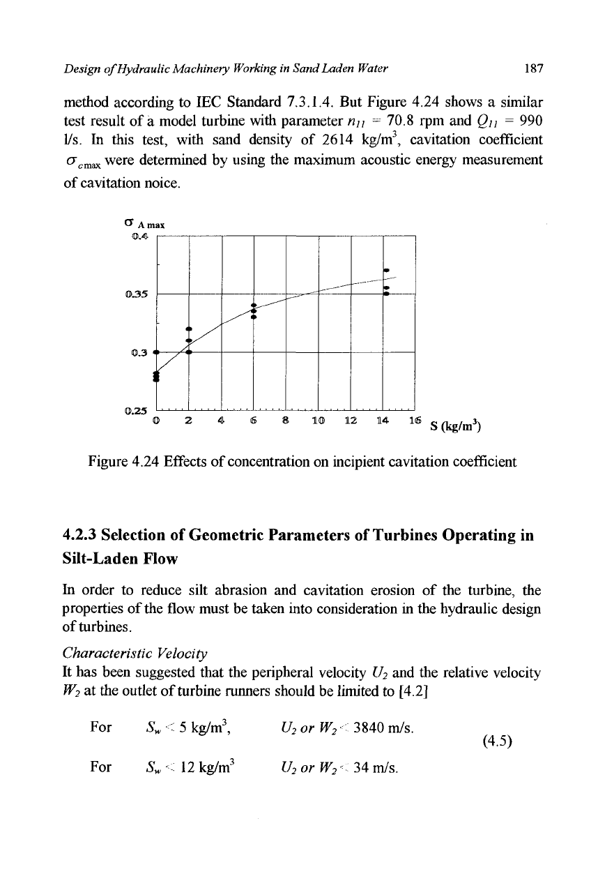
method according to IEC Standard 7.3.1.4. But Figure 4.24 shows a similar
test result of a model turbine with parameter n
u
= 70.8 rpm and Q
u
= 990
1/s. In this test, with sand density of 2614 kg/m
3
, cavitation coefficient
cr
cmax
were determined by using the maximum acoustic energy measurement
of cavitation noice.
C Ar
0.35
0.3
0.25
<
1.
A
/
1 y/
t
^1
m
2 4 6 8 10 12 14 16 „ ^ , 3N
Figure 4.24 Effects of concentration on incipient cavitation coefficient
4.2.3 Selection of Geometric Parameters of Turbines Operating in
Silt-Laden Flow
In order to reduce silt abrasion and cavitation erosion of the turbine, the
properties of the flow must be taken into consideration in the hydraulic design
of turbines.
Characteristic Velocity
It has been suggested that the peripheral velocity U
2
and the relative velocity
W
2
at the outlet of turbine runners should be limited to [4.2]
For S
w
< 5 kg/m
3
,
For S
w
< 12 kg/m
3
U
2
orW
2
<3M0mJs.
U
2
orW
2
~
34 m/s.
(4.5)
188
Abrasive Erosion and Corrosion of Hydraulic Machinery
Needless to say, the recommended limiting velocities are dependent on the
runner material. For example, it is indicated by the turbine operation
experience and the experimental data that for the stainless steel, Cr5Cu, the
critical peripheral velocity
U
2cr
at
the outlet of turbine runners working on silt-
laden rivers is only 20 m/s. For another stainless steel lCrl8Ni9Ti, it is 25
m/s.
For common steel and other alloy, such as, 20SiMn, 0Crl3Ni4Mo,
0Crl3Ni6Mo, it is 35 m/s. The critical velocity,
U
2cr
or
W
2cr
is the limited
velocity, if
the
velocity, U
2
or W
2
is larger than them, serious damage caused
by sand abration and cavitation erosion will occuers.
Specific Speed and Geometrical Parameters of Turbine Runner
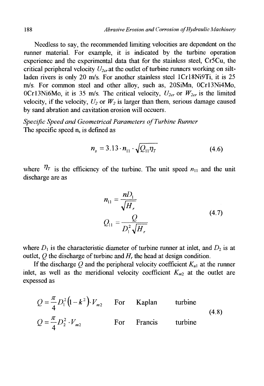
The specific speed n
s
is defined as
n,
=3.13-n
u
-yJQ
u
T]
T
(4.6)
where ^
T
is the efficiency of the turbine. The unit speed n
u
and the unit
discharge are as
n
u
nl\
a
Q
<47)
"~A
!
#;
where D\ is the characteristic diameter of turbine runner at inlet, and D
2
is at
outlet, Q the discharge of turbine and H
r
the head at design condition.
If the discharge Q and the peripheral velocity coefficient K
u
\ at the runner
inlet, as well as the meridional velocity coefficient K
m2
at the outlet are
expessed as
Q =
-D^-k
2
)-V
m2
For Kaplan turbine
Q =
—Dl-V
m2
For Francis turbine
(4.8)
Design of Hydraulic Machinery Working in Sand Laden Water 189
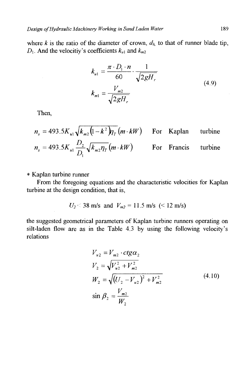
where k is the ratio of the diameter of crown, d
h
to that of runner blade tip,
D\.
And the velocitiy's coefficients k
u
\ and k
m2
_7r-D
r
n
*■""
60
v
k -
m2
1
JWr
4^H~r
Then,
(4.9)
n
s
= A93.SK
U]
-^k
m2
\^-k
2
)ri
T
{m- kW) For Kaplan turbine
A
*,= 493.5^, -j*-Jk~^(m-kW)
For Francis turbine
* Kaplan turbine runner
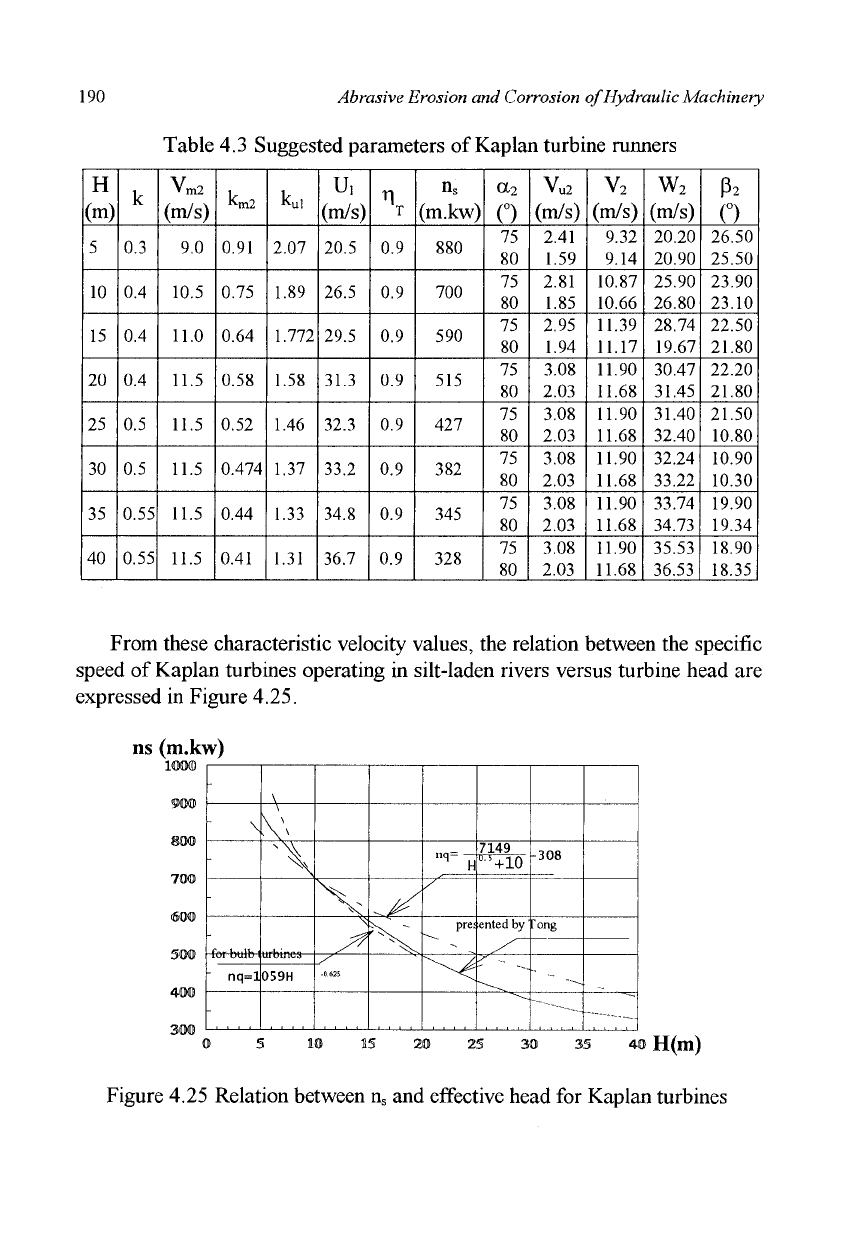
From the foregoing equations and the characteristic velocities for Kaplan
turbine at the design condition, that is,
U
2
< 38 m/s and V
m2
= 11.5 m/s (< 12 m/s)
the suggested geometrical parameters of Kaplan turbine runners operating on
silt-laden flow are as in the Table 4.3 by using the following velocity's
relations
v
ui =V
m2
-ctga
'2
ml
V
2
=ylV
u
2
2
+V
t
W
2
=yl{U
2
-V
u2
f
+
V,
V
sin /?
2
= —
2
ml
(4.10)
190 Abrasive Erosion and Corrosion of Hydraulic Machinery
Table 4.3 Suggested parameters of Kaplan turbine runners
H
(m)
5
10
15
20
25
30
35
40
k
0.3
0.4
0.4
0.4
0.5
0.5
0.55
0.55
v
m2
(m/s)
9.0
10.5
11.0
11.5
11.5
11.5
11.5
11.5
k
m2
0.91
0.75
0.64
0.58
0.52
0.474
0.44
0.41
k
u
i
2.07
1.89
1.772
1.58
1.46
1.37
1.33
1.31
u,
(m/s)
20.5
26.5
29.5
31.3
32.3
33.2
34.8
36.7
T
0.9
0.9
0.9
0.9
0.9
0.9
0.9
0.9
(m.kw)
880
700
590
515
427
382
345
328
a-2
o
75
80
75
80
75
80
75
80
75
80
75
80
75
80
75
80
v
u2
(m/s)
2.41
1.59
2.81
1.85
2.95
1.94
3.08
2.03
3.08
2.03
3.08
2.03
3.08
2.03
3.08
2.03
v
2
(m/s)
9.32
9.14
10.87
10.66
11.39
11.17
11.90
11.68
11.90
11.68
11.90
11.68
11.90
11.68
11.90
11.68
w
2
(m/s)
20.20
20.90
25.90
26.80
28.74
19.67
30.47
31.45
31.40
32.40
32.24
33.22
33.74
34.73
35.53
36.53
P
2
o
26.50
25.50
23.90
23.10
22.50
21.80
22.20
21.80
21.50
10.80
10.90
10.30
19.90
19.34
18.90
18.35
From these characteristic velocity values, the relation between the specific
speed of Kaplan turbines operating in silt-laden rivers versus turbine head are
expressed in Figure 4.25.
ns (m.kw)
-
\
-
-
nq=l
-
\
\
\ \
^\
059H
N^
V
-0625
^
"^.
nq
H
S~
pre;
<^
7149
Ub
+10
ented by'
/^~
s -
-308
ong
~ - -^
~'~-—-----
0 5 10 15 20 25 30 35 40 H(m)
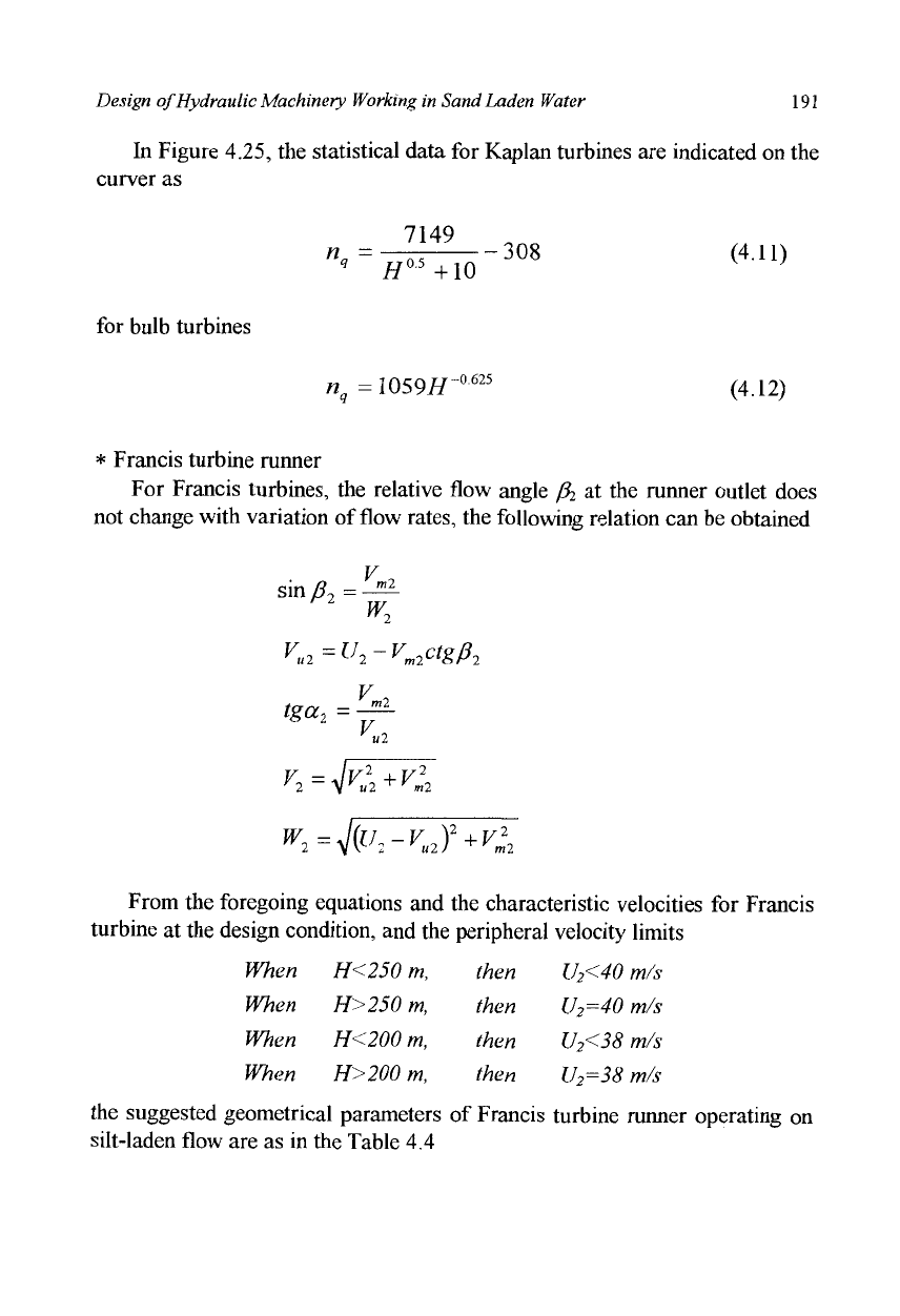
Figure 4.25 Relation between n
s
and effective head for Kaplan turbines
Design of Hydraulic Machinery Working in Sand Laden Water 191
In Figure 4.25, the statistical data for Kaplan turbines are indicated on the
curver as
7149
n =—- 308 (4.11)
q
H
05
+10
for bulb turbines
n
q
= 1059/T
0625
(4.12)
* Francis turbine runner
For Francis turbines, the relative flow angle /% at the runner outlet does
not change with variation of flow rates, the following relation can be obtained
sin
fl
2
=
w
2
V
u2
=U
2
-V
m2
ctg/3
2
v,
*u2
T2
ml
v
2
= 4Vu2+K
W
2
=yl{U
2
-V
u2
f+V
r
2
m2
From the foregoing equations and the characteristic velocities for Francis
turbine at the design condition, and the peripheral velocity limits
When
When
When
When
H<250 m,
H>250 m,
H<200 m,
H>200 m,
then
then
then
then
U
2
<40
m/s
U
2
=40
m/s
U
2
<38
m/s
U
2
=38
m/s
the suggested geometrical parameters of Francis turbine runner operating on
silt-laden flow are as in the Table 4.4

192
Abrasive Erosion
and
Corrosion
of
Hydraulic Machinery
Table
4.4
Suggested parameters
of
Francis turbine runner
H
(m)
u
2
(m/s)
W
2
(m/s)
D
2
D.
u,
(m/s)
k
u
i
(m/s)
km2
P2
(°)
v
u2
(m/s)
a
2
(°)
v
2
(m/s)
a,
(°)
v„,
(m/s)
(m/s)
W,
(m/s)
mkw
35
29
25
1.18
24.60
0.940
8.7
0.332
20.36
5.56
57.40
10.32
28.0
16.36
18.53
11.98
299.2
50
30.5
28
1.15
26.54
0.848
9.4
0.300
19.62
4.13
66.30
10.27
26.5
18.85
21.07
12.15
250.0
70
33
29.5
1.11
29.70
0.802
9.9
0.267
19.60
5.20
62.30
11.18
25.5
20.76
23.00
11.95
215.4
100
36.5
32.5
1.06
34.42
0.777
10.2
0.230
18.30
5.65
61.02
11.66
24.0
22.91
25.08
15.18
185.0
120
38
34.2
1.03
36.90
0.761
10.3
0.212
17.53
5.39
62.38
11.63
23.8
23.35
25.52
17.02
169.0
150
38.5
36
0.98
39.27
0.724
10.5
0.194
16.96
4.07
69.00
11.26
22.0
25.99
28.03
16.90
146.3
180
39
37.7
0.93
41.93
0.706
10.6
0.178
16.33
2.82
75.10
0.97
21.8
26.50
28.54
18.72
130.0
200
39.5
38
0.90
43.85
0.70
10.6
0.169
16.20
3.02
74.12
11.02
21.0
27.61
29.58
19.40
121.4
250
39.8
38
0.84
47.36
0.677
10.7
0.153
16.35
3.33
72.73
11.21
19.5
30.20
32.05
20.22
104.1
300
40
38
0.79
50.64
0.66
10.8
0.141
16.51
3.57
71.74
11.37
18.0
33.24
34.95
20.48
91.6
350
40
38
0.74
54.04
0.652
10.9
0.132
16.67
3.60
71.72
11.48
16.5
36.80
38.38
20.40
82.0
400
40
38
0.70
57.16
0.646
11.0
0.124
16.83
3.64
71.69
11.59
15.5
39.66
41.16
20.67
74.6

Design of Hydraulic Machinery Working in Sand Laden Water 193
From table 4.4, it is obtained that the relative flow angle
(5
2
is in the range
from 15° to 20°, the absolute velocity at the runner outlet at the design
condition, V
2
, is less than 15 m/s, and at the design condition, the peripheral
component of absolute velocity at the runner outlet,
V
u2
,
is positive.
The relation between the specific speed of turbines operating in silt-laden
rivers and the turbine head are expressed in Figure 4.26 for Francis turbines.
Statistical data are also plotted on these curves, such as (Tong, 1993) [4.4]
n=2357H
-0.538
n
q
=638H
-0.512
(4.13)
ns (m.Kw)
350
300
250
300
150
100
so
: \
\
- \ \
1
\
s
1
/
/
^x--.
^=2
nq=
/
--. j
357"
638
resen
?5
C
.
\™
V
12
ed by
_..__
Tong
0 §0 100 150 200250300350400 H(ltl)
Figure 4.26 Relation between n
s
and effective head for Francis turbines
Unit Speed and Unit Discharge
The unit speed n
u
and the unit discharge
Qw
can be expressed as follows:
For Kaplan turbines
