Charles M. Kozierok The TCP-IP Guide
Подождите немного. Документ загружается.


The TCP/IP Guide - Version 3.0 (Contents) ` 431 _ © 2001-2005 Charles M. Kozierok. All Rights Reserved.
transport layer messages, transport headers and all, into its IP Data field. This immediately
presents us with a potential issue: matching the size of the IP datagram to the size of the
underlying data link layer frame size.
Matching IP Datagram Size to Underlying Network Frame Size
The underlying network that a device uses to connect to other devices could be LAN
connection like Ethernet or Token Ring, a wireless LAN link such as 802.11, or a dialup,
DSL, T-1 or other WAN connection. Each physical network will generally use its own frame
format, and each format has a limit on how much data can be sent in a single frame. If the
IP datagram is too large for the data link layer frame format's payload section, we have a
problem!
For example, consider an FDDI. The maximum size of the data field in FDDI is around
4,470, depending on whether or not SNAP is used. This means FDDI can handle an IP
datagram of up to 4,470 bytes. In contrast, a regular Ethernet frame uses a frame format
that limits the size of the payload it sends to 1,500 bytes. This means Ethernet can't deal
with IP datagrams greater than 1,500 bytes in size.
Now, remember that in sending a datagram across an internetwork, it may pass across
more than one physical network. To access a site on the Internet, for example, we typically
send a request through our local router, which then connects to other routers that eventually
relay the request to the Internet site. Each hop as the datagram is forwarded may use a
different physical network, with a different maximum underlying frame size.
The whole idea behind a network layer protocol is to implement this concept of a “virtual
network” where devices talk even though they are far away. This means that higher layers
shouldn't need to worry about details like the size limits of underlying data link layer technol-
ogies. However, someone has to worry about it. This task falls to the Internet Protocol.
Maximum Transmission Unit (MTU) and Datagram Fragmentation
The IP implementation of all devices on an IP internet needs to be aware of the capacity of
the technology used by that implementation for its immediate data link layer connection to
other devices. This limit is called the maximum transmission unit (MTU) of the network. This
term is also sometimes seen as the maximum transfer unit.
If an IP layer receives a message to be sent across the internetwork, it looks at the size of
the message and then computes how large the IP datagram would be after the addition of
the 20 or more bytes needed for the IP header. If the total length is greater than the MTU of
the underlying network, the IP layer will fragment the message into multiple IP fragments.
So, if a host is connected using an Ethernet LAN to its local network, it may use an MTU of
1,500 for IP datagrams, and will fragment anything larger. Figure 88 shows an example of
differing MTUs and fragmentation.
The TCP/IP Guide - Version 3.0 (Contents) ` 432 _ © 2001-2005 Charles M. Kozierok. All Rights Reserved.
Key Concept: The size of the largest IP datagram that can be transmitted over a
physical network is called that network’s maximum transmission unit (MTU). If a
datagram is passed from a network with a high MTU to one with a low MTU, it must
be fragmented to fit the network with the smaller MTU.
Since some physical networks on the path between devices may have a smaller MTU than
others, it may be necessary to fragment more than once. For example, suppose the source
device wants to send an IP message 12,000 bytes long. Its local connection has an MTU of
3,300 bytes. It will have to divide this message into four fragments for transmission: three
that are about 3,300 bytes long and a fourth remnant about 2,100 bytes long. (I'm oversim-
plifying by ignoring the extra headers required; the next topic includes the full details of the
fragmentation process.)
Multiple-Stage Fragmentation
While the fragments above are in transit, they may need to pass over a hop between two
routers where the physical network's MTU is only 1,300 bytes. In this case, each of the
fragments will again need to be fragmented. The 3,300 byte fragments will end up in three
pieces each (two of about 1,300 bytes and one of around 700 bytes) and the final 2,100-
byte fragment will become a 1300-byte and 800-byte fragment. So instead of having four
fragments, we will end up with eleven (3*3+1*2)! This is illustrated in Figure 89.
Internet Minimum MTU: 576 Bytes
Each router must be able to fragment as needed to handle IP datagrams up to the size of
the largest MTU used by networks to which they attach. Routers are also required, as a
minimum, to handle an MTU of at least 576 bytes. This value is specified in RFC 791, and
was chosen to allow a “reasonable sized” data block of at least 512 bytes, plus room for the
standard IP header and options. Since it is the minimum size specified in the IP standard,
576 bytes has become a common default MTU value used for IP datagrams. Even if a host
is connected over a local network with an MTU larger than 576, it may choose to use an
MTU value of 576 anyway, to ensure that no further fragmentation will be required by inter-
mediate routers.
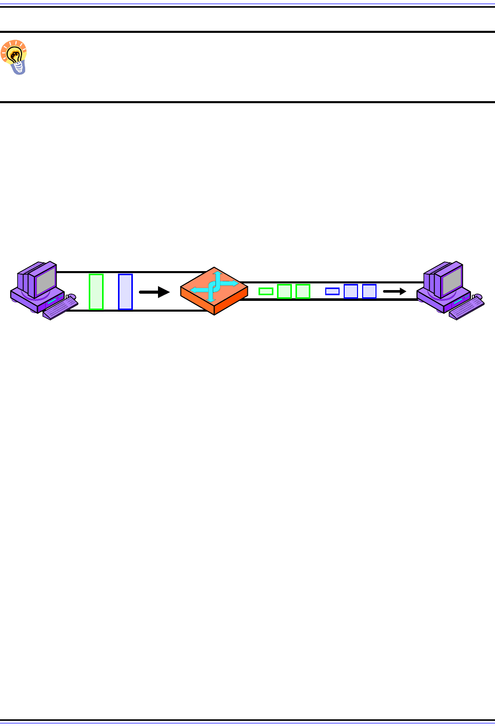
Figure 88: IP Maximum Transmission Unit (MTU) and Fragmentation
In this simple example, Device A is sending to Device B over a small internetwork consisting of one router and
two physical links. The link from A to the router has an MTU of 3,300 bytes, but from the router to B it is only
1,300 bytes. Thus, any IP datagrams over 1,300 bytes will need to be fragmented.
MTU 3,300
MTU 1,300
Device A Device B
The TCP/IP Guide - Version 3.0 (Contents) ` 433 _ © 2001-2005 Charles M. Kozierok. All Rights Reserved.
Note that while intermediate routers may further fragment an already-fragmented IP
message, intermediate devices do not reassemble fragments. Reassembly is done only by
the recipient device. This has some advantages and some disadvantages, as we will see
when we examine the reassembly process.
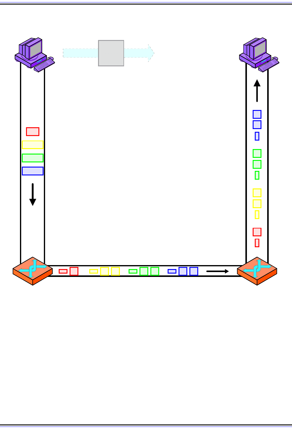
Figure 89: IPv4 Datagram Fragmentation
This example shows illustrates a two-step fragmentation of a large IP datagram. The boxes represent
datagrams or datagram fragments and are shown to scale. The original datagram is 12,000 bytes in size,
represented by the large gray box. To transmit this data over the first local link, Device A splits it into four
fragments, shown at left in four primary colors. The first router must fragment each of these into smaller
fragments to send them over the 1,300-byte MTU link, as shown on the bottom. Note that the second router
does not reassemble the 1,300-byte fragments, even though its link to Device B has an MTU of 3,300 bytes.
(Figure 90 shows the process by which the fragments in this example are created.)
Local Link
MTU 3,300
Local Link
MTU 3,300
IP Datagram
12,000 Bytes
Router Connection
MTU 1,300
Device A Device B

The TCP/IP Guide - Version 3.0 (Contents) ` 434 _ © 2001-2005 Charles M. Kozierok. All Rights Reserved.
MTU Path Discovery
When trying to send a great deal of data, efficiency in message transmissions becomes
important. The larger each IP datagram we send, the smaller the percentage of bytes
wasted for overhead such as header fields. This means that ideally, we want to use as large
an MTU as possible without fragmentation occurring.
Determining the optimal MTU to use for a route between two devices requires knowing the
MTU of every link on that route—information that the end-points of the connection simply
don’t have. They can determine the MTU of the overall route, however, using a clever
technique called path MTU discovery. I call this technique “clever” because it does not use
any special feature designed for the particular purpose of determining a route’s MTU, but
rather an error reporting mechanism built into TCP/IP Internet Control Message Protocol
(ICMP).
One of the message types defined in ICMPv4 is the Destination Unreachable message,
which is returned under various conditions where an IP datagram cannot be delivered. One
of these situations is when a datagram is sent that is too large to be forwarded by a router
over a physical link but which has its Don’t Fragment (DF) flag set to prevent fragmentation.
In this case, the datagram must be discarded and a Destination Unreachable message sent
back to the source. A device can exploit this capability by testing the path with datagrams of
different sizes, to see how large they must be before they are rejected.
The source node typically sends a datagram that has the MTU of its local physical link,
since that represents an upper bound on the MTU of any path to or from that device. If this
goes through without any errors, it knows it can use that value for future datagrams to that
destination. If it gets back any Destination Unreachable - Fragmentation Needed and DF
Set messages, this means some other link between it and the destination has a smaller
MTU. It tries again using a smaller datagram size, and continues until it finds the largest
MTU that can be used on the path.
IP Message Fragmentation Process
When an IP datagram is too large for the maximum transmission unit (MTU) of the under-
lying data link layer technology used for the next leg of its journey, it must be fragmented
before it can be sent across the network. The higher-layer message to be transmitted is not
sent in a single IP datagram but rather broken down into pieces called fragments that are
sent separately. In some cases, the fragments themselves may need to be fragmented
further.
Fragmentation Issues and Concerns
Fragmentation is necessary to implement a network-layer internet that is independent of
lower layer details, but introduces significant complexity to IP. Remember that IP is an
unreliable, connectionless protocol. IP datagrams can take any of several routes on their
way from the source to the destination, and some may not even make it to the destination at
all. When we fragment a message we make a single datagram into many, which introduces
several new issues to be concerned with:

The TCP/IP Guide - Version 3.0 (Contents) ` 435 _ © 2001-2005 Charles M. Kozierok. All Rights Reserved.
☯ Sequencing and Placement: The fragments will typically be sent in sequential order
from the beginning of the message to the end, but they won't necessarily show up in
the order in which they were sent. The receiving device must be able to determine the
sequence of the fragments to reassemble them in the correct order. In fact, some
implementations send the last fragment first, so the receiving device will immediately
know the full size of the original complete datagram. This makes keeping track of the
order of segments even more essential.
☯ Separation of Fragmented Messages: A source device may need to send more than
one fragmented message at a time; or, it may send multiple datagrams that are
fragmented en route. This means the destination may be receiving multiple sets of
fragments that must be put back together. Imagine a box into which the pieces from
two, three or more jigsaw puzzles have been mixed and you understand this issue.
☯ Completion: The destination device has to be able to tell when it has received all of
the fragments so it knows when to start reassembly (or when to give up if it didn't get
all the pieces).
To address these concerns and allow the proper reassembly of the fragmented message,
IP includes several fields in the IP format header that convey information from the source to
the destination about the fragments. Some of these contain a common value for all the
fragments of the message, while others are different for each fragment.
The IP Fragmentation Process: An Example
The device performing the fragmentation follows a specific algorithm to divide the message
into fragments for transmission. The exact implementation of the fragmentation process
depends on the device. Let's take the same example from the previous topic, an IP
message 12,000 bytes wide (including the 20-byte IP header) that needs to be sent over a
link with an MTU of 3,300. Here's a typical method by which this fragmentation might be
performed (you may find the illustration in Figure 90 helpful):
1. Create First Fragment: The first fragment is created by taking the first 3,300 bytes of
the 12,000-byte IP datagram. This includes the original header, which becomes the IP
header of the first fragment (with certain fields changed as described below). So,
3,280 bytes of data are in the first fragment. This leaves 8,700 bytes to encapsulate
(11,980 minus 3,280).
2. Create Second Fragment: The next 3,280 bytes of data are taken from the 8,700
bytes that remain after the first fragment was built, and paired with a new header to
create fragment #2. This leaves 5,420 bytes.
3. Create Third Fragment: The third fragment is created from the next 3,280 bytes of
data, with a 20-byte header. This leaves 2,140 bytes of data.
4. Create Fourth Fragment: The remaining 2,140 bytes are placed into the fourth
fragment, with a 20-byte header of course.
I want to emphasize two important points here. First, IP fragmentation does not work by
fully encapsulating the original IP message into the Data fields of the fragments. If this were
done, the first 20 bytes of the Data field of the first fragment would contain the original IP
header. This technique is used by some other protocols, such as the PPP Multilink Protocol,
but not by IP. The original IP header is “transformed” into the IP header of the first fragment.
The TCP/IP Guide - Version 3.0 (Contents) ` 436 _ © 2001-2005 Charles M. Kozierok. All Rights Reserved.
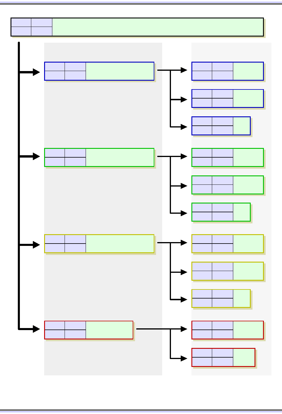
Figure 90: IPv4 Datagram Fragmentation Process
In this diagram, the MF and Fragment Offset fields of each fragment are shown for reference. The Data fields
are shown to scale (the length of each is proportional to the number of bytes in the fragment.)
MF Offset
Data
11,980 bytes
0 0
MF Offset
Data
3,280 bytes
1 0
MF Offset
Data
3,280 bytes
1 410
MF Offset
Data
3,280 bytes
1 820
MF Offset
Data
2,140 bytes
0 1,230
MF Offset
1 820
MF Offset
1 980
MF Offset
1 1,140
Data
720 b
Data
1,280 bytes
Data
1,280 bytes
MF Offset
1 0
Data
1,280 bytes
MF Offset
1 160
MF Offset
1 320
Data
720 b
Data
1,280 bytes
MF Offset
1 410
MF Offset
1 570
MF Offset
1 730
Data
720 b
Data
1,280 bytes
Data
1,280 bytes
MF Offset
1 1,230
MF Offset
0 1,390
Data
860 b
Data
1,280 bytes
First Fragmentation
3,300-Byte MTU
Fragment 1: Data Bytes 0 - 3,279
Fragment 2: Data Bytes 3,280 - 6,559
Fragment 4: Data Bytes 9,840 - 11,979
Fragment 3: Data Bytes 6,560 - 9,839
Second Fragmentation
1,300-Byte MTU
Fragment 1A: Bytes 0 - 1,279
Fragment 1B: Bytes 1,280 - 2,559
Fragment 1C: Bytes 2,560 - 3,279
Fragment 2A: Bytes 3,280 - 4,559
Fragment 2B: Bytes 4,560 - 5,839
Fragment 2C: Bytes 5,840 - 6,559
Fragment 1A: Bytes 6,560 - 7,839
Fragment 1B: Bytes 7,840 - 9,119
Fragment 1C: Bytes 9,120 - 9,839
Fragment 1A: Bytes 9,840 - 11,119
Fragment 1B: Bytes 11,120 - 11,979

The TCP/IP Guide - Version 3.0 (Contents) ` 437 _ © 2001-2005 Charles M. Kozierok. All Rights Reserved.
Second, note that the total number of bytes transmitted increases: we are sending 12,060
bytes (3,300 times three plus 2,160) instead of 12,000. The extra 60 bytes are from the
additional headers in the second, third and fourth fragments. (The increase in size could
theoretically be even larger if the headers contain options.)
Fragmentation-Related IP Datagram Header Fields
When a sending device or router fragments a datagram, it must provide information that will
allow the receiving device to be able to identify the fragments and reassemble them into the
datagram that was originally sent. This information is recorded by the fragmenting device in
a number of fields in the IP datagram header.
Total Length
After fragmenting, this field indicates the length of each fragment, not the length of the
overall message. Normally, the fragment size is selected to match the MTU value in bytes.
However, fragments must have a length that is a multiple of 8, to allow proper offset specifi-
cation (see below). The last fragment will usually be shorter than the others because it will
contain a “leftover” piece, unless the message length happens to be an exact multiple of the
fragment size.
Identification
To solve the “many jigsaw puzzles in a box” problem, a unique identifier is assigned to each
message being fragmented. Consider this like writing a different number on the bottom of
each piece of a jigsaw puzzle before tossing it into the box. This value is placed in the
Identification field in the IP header of each fragment sent. The Identification field is 16 bits
wide, so a total of 65,536 different identifiers can be used.
Obviously, we want to make sure that each message sent between the same source and
destination that is being fragmented has a different identifier. The source can decide how it
generates unique identifiers. This may be done through something as simple as a counter
that is incremented each time a new set of fragments is created.
More Fragments
This flag is set to a 1 for all fragments except the last one, which has it set to 0. When the
fragment with a value of 0 in the More Fragments flag is seen, the destination knows it has
received the last fragment of the message.
Fragment Offset
This field solves the problem of sequencing fragments by indicating to the recipient device
where in the overall message each particular fragment should be placed. The field is 13 bits
wide, so the offset can be from 0 to 8191. Fragments are specified in units of 8 bytes, which
is why fragment length must be a multiple of 8. Uncoincidentally, 8191 * 8 is 65,528, just
about the maximum size allowed for an IP datagram.

The TCP/IP Guide - Version 3.0 (Contents) ` 438 _ © 2001-2005 Charles M. Kozierok. All Rights Reserved.
Let's take the same example from above. The first fragment would have a Fragment Offset
of 0. The second would have an offset of 410 (3,280 divided by 8). The third would have an
offset of 820 (6,560 divided by 8). The fourth would have an offset of 1230.
Key Concept: When an MTU requirement forces a datagram to be fragmented, it is
split into several smaller IP datagrams, each containing part of the original. The
header of the original datagram is changed into the header of the first fragment, and
new headers are created for the other fragments. Each is set to the same Identification
value to mark them as part of the same original datagram. The Fragment Offset of each is
set to the location where the fragment belongs in the original. The More Fragments field is
set to 1 for all fragments but the last, to let the recipient know when it has received all the
fragments.
IP Header Flags Related to Fragmentation
In addition to the fields above, there are a couple of flags in the IP header related to
fragmentation.
The Copied Flag
If a datagram containing options must be fragmented, some of the options may be copied to
each of the fragments. This is controlled by the Copied flag in each option field.
The Don’t Fragment Flag
This flag can be set to 1 by a transmitting device to specify that a datagram not be
fragmented in transit. This may be used in certain circumstances where the entire message
must be delivered intact as pieces may not make sense. It may also be used if the desti-
nation device has a limited IP implementation and can't reassemble fragments, and is also
used for testing the maximum transmission unit (MTU) of a link. Normally, however, devices
don't care about fragmentation and this field is left at zero.
What happens if a router encounters a datagram too large to pass over the next physical
network but with the Don't Fragment bit set to 1? It can't fragment the datagram and it can't
pass it along either, so it is “stuck”. It will generally drop the datagram, and then send back
a special ICMP Destination Unreachable error message: “Fragmentation Needed and Don't
Fragment Bit Set”. This is used in MTU Path Discovery as described in the preceding
section.
IP Message Reassembly Process
When a datagram is fragmented, either by the originating device or by one or more routers
transmitting the datagram, it becomes multiple fragment datagrams. The destination of the
overall message must collect these fragments and then reassemble them into the original
message. Reassembly is accomplished by using the special information in the fields we
saw in the preceding topic to help us “put the jigsaw puzzle back together again”.

The TCP/IP Guide - Version 3.0 (Contents) ` 439 _ © 2001-2005 Charles M. Kozierok. All Rights Reserved.
Asymmetry of Fragmentation and Reassembly
It's important to understand that while reassembly is the complement to fragmentation, the
two processes are not symmetric. A primary differentiation between the two is that while
intermediate routers can fragment a single datagram or further fragment a datagram that is
already a fragment, intermediate devices do not perform reassembly. This is done only by
the ultimate destination of the IP message. So, if a datagram at an intermediate router on
one side of a physical network with an MTU of 1,300 causes fragmentation of a 3,300 byte
datagram, the router on the other end of this 1,300 MTU link will not restore the 3,000 byte
datagram to its original state. It will send all the 1,300 byte fragments on down the internet,
as shown in Figure 89.
There are a number of reasons why the decision was made to implement IP reassembly
this way. Perhaps the most important one is that fragments can take different routes to get
from the source to destination, so any given router may not see all the fragments in a
message. Another reason is that having routers need to worry about reassembling
fragments would increase their complexity. Finally, as we will see, reassembly of a message
requires that we wait for all fragments before sending on the reassembled message. Having
routers do this would slow routing down. Since routers don't reassemble they can immedi-
ately forward all fragments on to the ultimate recipient.
However, there are drawbacks to this design as well. One is that it results in more smaller
fragments traveling over longer routes than if intermediate reassembly occurred. This
increases the chances of a fragment going missing and the entire message being
discarded. Another is a potential inefficiency in the utilization of data link layer frame
capacity. In the example above, the 1,300-byte fragments would not be reassembled back
into a 3,300 byte datagram at the end of the 1,000-MTU link. If the next link after that one
also had an MTU of 3,300, we would have to send three frames, each encapsulating a
1,300-byte fragment, instead of a single larger frame, which is slightly slower.
Key Concept: In IPv4, fragmentation can be performed by a router between the
source and destination of an IP datagram, but reassembly is only done by the desti-
nation device.
The Reassembly Process
As we saw in looking at how fragmentation works, it involves a fair bit of complexity. Several
IP header fields are filled in when a message is fragmented to give the receiving device the
information it requires to properly reassemble the fragments. The receiving device follows a
procedure to keep track of the fragments as they are received and build up its copy of the
total received message from the source device. Most of its efforts are geared around
dealing with the potential difficulties associated with IP being an unreliable protocol.
The details of implementation of the reassembly process are specific to each device, but
generally include the following functions:

The TCP/IP Guide - Version 3.0 (Contents) ` 440 _ © 2001-2005 Charles M. Kozierok. All Rights Reserved.
☯ Fragment Recognition and Fragmented Message Identification: The recipient
knows it has received a message fragment the first time it sees a datagram with the
More Fragments bit set to one or the Fragment Offset a value other than zero. It
identifies the message based on: the source and destination IP addresses; the
protocol specified in the header; and the Identification field generated by the sender.
☯ Buffer Initialization: The receiving device initializes a buffer where it can store the
fragments of the message as they are received. It keeps track of which portions of this
buffer have been filled with received fragments, perhaps using a special table. By
doing this, it knows when the buffer is partially filled with received fragments and when
it is completely full.
☯ Timer Initialization: The receiving device sets up a timer for reassembly of the
message. Since it is possible that some fragments may never show up, this timer
ensures that the device will not wait “forever” trying to reassemble the message.
☯ Fragment Receipt and Processing: Whenever a fragment of this message arrives
(as indicated by it having the same source and destination addresses, protocol and
Identification as the first fragment), the fragment is processed. It is inserted into the
message buffer in the location indicated by its Fragment Offset field. The device also
makes note of the fact that this portion of the message has been received.
Reassembly is finished when the entire buffer has been filled and the fragment with the
More Fragments bit set to zero is received, indicating that it is the last fragment of the
datagram. The reassembled datagram is then processed like a normal, unfragmented
datagram would be. On the other hand, if the timer for the reassembly expires with any of
the fragments missing, the message cannot be reconstructed. The fragments are
discarded, and an ICMP Time Exceeded message generated. Since IP is unreliable, it
relies on higher layer protocols such as TCP to determine that the message was not
properly received and then retransmit it.