Bryan L. Programmable controllers. Theory and implementation
Подождите немного. Документ загружается.


599
CHAPTER
13
Data Measurements
and Transducers
Industrial Text & Video Company 1-800-752-8398
www.industrialtext.com
SECTION
4
PLC Process
Applications
13-8 VIBRATION TRANSDUCERS
Vibration transducers are used in system applications that require the
detection of vibration, which can severely damage process control equip-
ment. For example, a vibration detector can monitor the amount of vibration
in a large motor, thereby preventing potential failure of the bearings. Vibra-
tion transducers also sense excessive machine vibration, helping to prevent
catastrophic equipment damage, extensive repairs, and downtime. Some of
the most common causes of system vibration failures, along with their
frequencies, are:
• imbalance of a rotating member (approximately 40%)
• misalignment (15%)
• defective bearings (15%)
• defective belts (15%)
• other miscellaneous causes (15%)
Before we explain vibration transducers, let’s first explore some of the basics
of vibrational motion.
VIBRATION BASICS
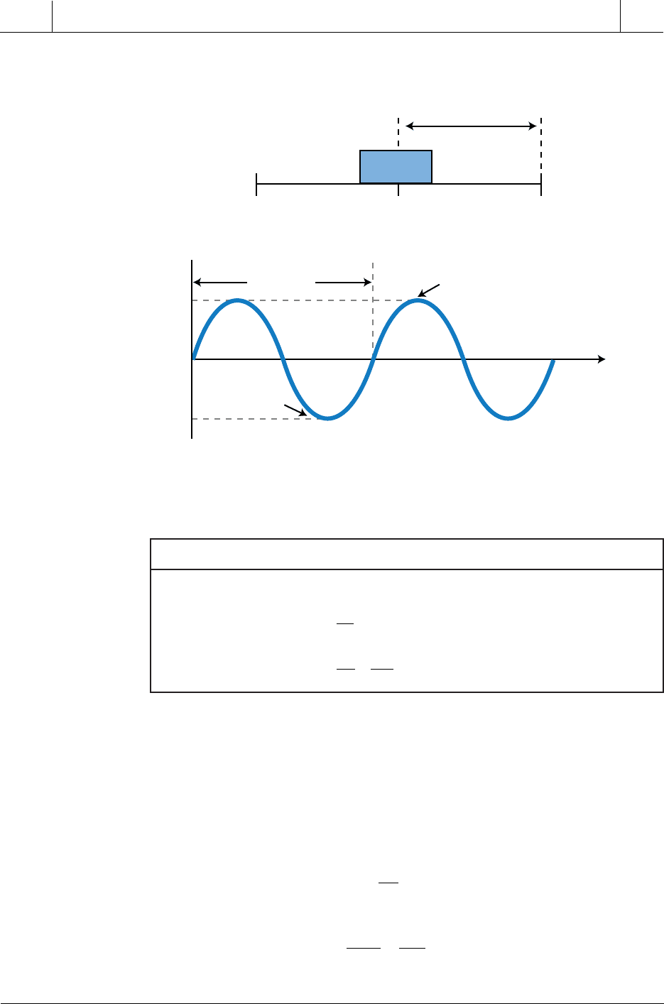
Vibration is defined as the oscillatory movement of a mass about a reference
position characterized by displacement, velocity, and acceleration. Displace-
ment (s) is the distance that the mass moves from its reference position in
meters (see Figure 13-34), velocity (v) is the speed at which the mass moves
in meters per second (m/sec), and acceleration (a) is the rate of change of the
mass’s velocity per second (m/sec
2
). Table 13-9 displays the equations for
these vibration motion parameters. Vibration also involves other parameters,
including frequency, amplitude, and wave form. Vibration can be mathemati-
cally defined in terms of periodic motion of a mass from a reference position
by:
ss t
t
=
max
sin
ω
where:
s
s
t
=
=
=
the position and distance of movement in meters (displacement)
the maximum displacement in meters (peak displacement)
the angular frequency in radians per second
max
ω
600
SECTION
4
PLC Process
Applications
Industrial Text & Video Company 1-800-752-8398
www.industrialtext.com
CHAPTER
13
Data Measurements
and Transducers
The angular frequency can also be expressed as angular velocity where ω =
2πf. In vibration, velocity is the first derivative of displacement, while
acceleration is the first derivative of velocity (or the second derivative of
displacement):
vt
ds
dt
st
t
( ) cos==−
ωω
at
dv t
dt
ds
dt
st
t
()
()
sin===−
2
0
2
ωω
Figure 13-34. Displacement.
Table 13-9. Motion parameters associated with vibration.
sft
v
ds
dt
a
dv
dt
ds
dt
=
=
==
()
2
2
retemaraPnoitauqEnoitoMnoitpircseD
tnemecalpsiD emitfonoitcnufasatnemecalpsiD
yticoleV tnemecalpsidfoevitaviredtsriF
noitareleccA tnemecalpsidfoevitavireddnoceS
Peak
Distance
Mass
0
s
max
+
s
max
–
s
max
–s
max
Time (
t
)
Displacement
Period
T
1

601
CHAPTER
13
Data Measurements
and Transducers
Industrial Text & Video Company 1-800-752-8398
www.industrialtext.com
SECTION
4
PLC Process
Applications
All three vibration terms—displacement, velocity, and acceleration—have
the same periodic frequency. Another important term in vibration monitoring
is the peak acceleration, which is frequency squared (ω
2
)
times the peak
displacement (s
0
):
as
peak
=
0
2
ω
This peak acceleration equation indicates that acceleration can become
large even with very small displacement, since the displacement term is
multiplied by the square of the frequency. Thus, acceleration can easily reach
a level of several g values (1g = 9.8 m/sec
2
), creating a potentially destructive
vibration. Table 13-10 lists the characteristics of several types of vibration.
EXAMPLE 13-12
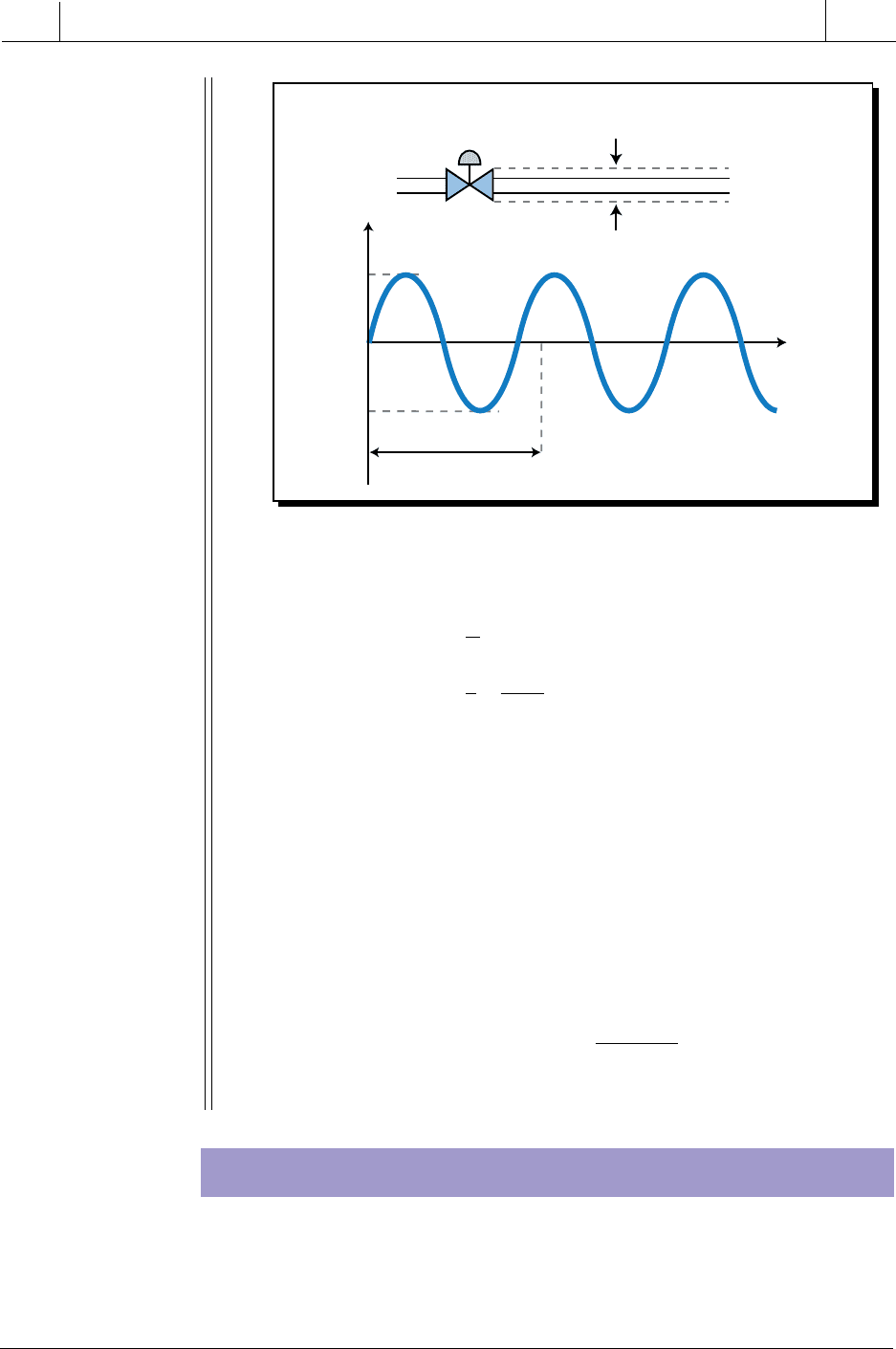
A steam pipe in a heat batching system (see Figure 13-35) vibrates at
a frequency of 8 cycles per second (8 Hz) with a peak displacement
of 10 mm (1 cm or 0.01 m). (a) Find and plot the displacement
equation indicating the period, and (b) calculate the peak accelera-
tion in m/sec
2
and its equivalent in g units.
S
OLUTION
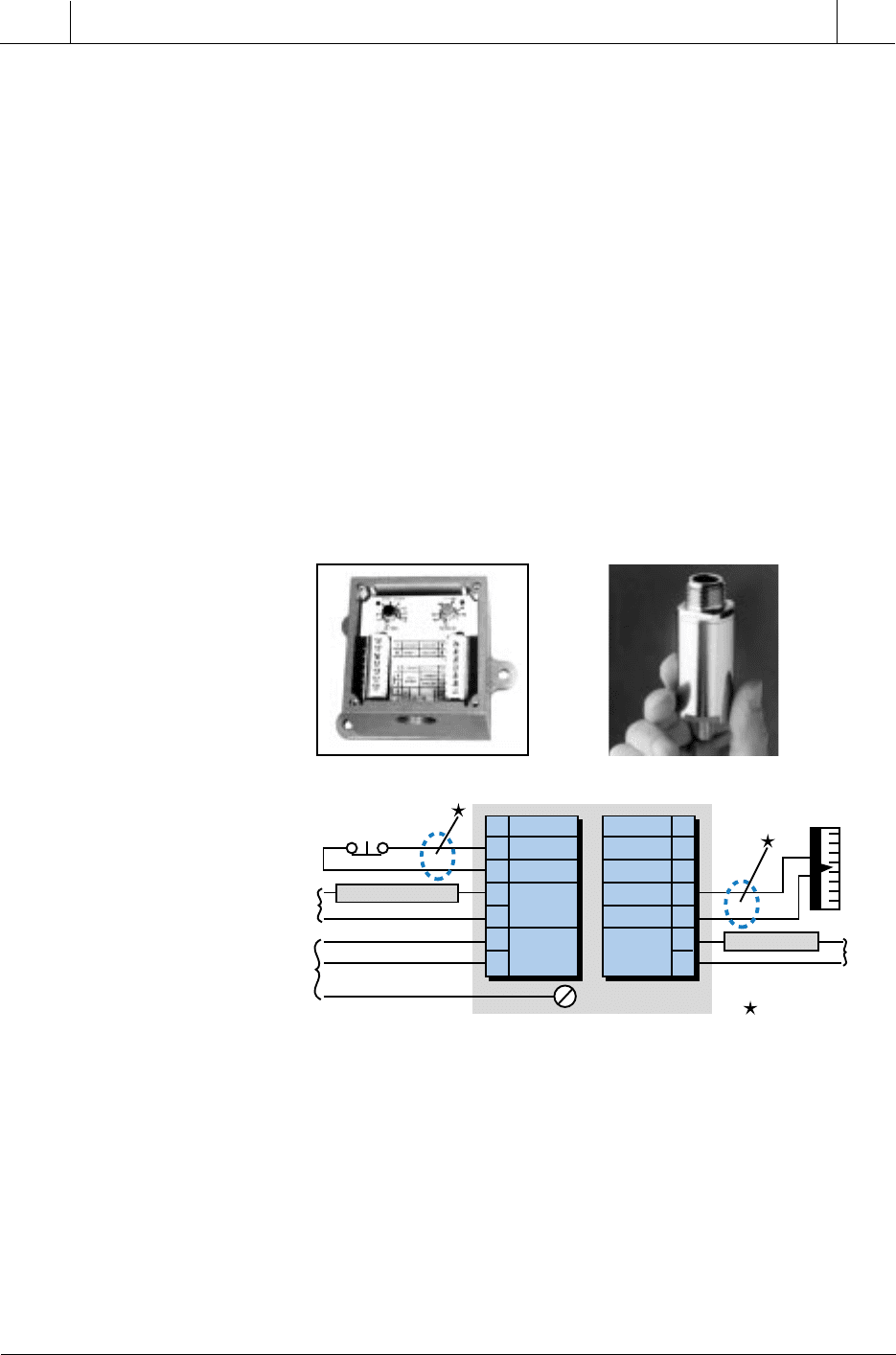
(a) Figure 13-36 presents the graph of displacement versus time of
vibration, which is given mathematically by the equation:
ss t
sft
t
t
t
=
=
=
=
max
max
sin
sin
( . )sin ( )
( . )sin .
ω
π
π
2
001 2 8
0 01 50 265
Figure 13-35. Heat batching system.
Steam
Pipe vibrating at 8 Hz
with peak displacement
of 10 mm

602
SECTION
4
PLC Process
Applications
Industrial Text & Video Company 1-800-752-8398
www.industrialtext.com
CHAPTER
13
Data Measurements
and Transducers
Table 13-10. Vibration identification guide.
(Courtesy of PMC/BETA Corp., Natick, MA)
esuaC
otevitaleRycneuqerF
mprenihcaM
ebortS-esahP
erutciP
edutilpmAsetoN
ecnalabmI1×mpr
ydaetselgniS
kramecnerefer
,ydaets,laidaR
otlanoitroporp
ecnalabmi
noitarbivfoesuacnommoC
noitcirfitnaevitcefeD
gniraeb
001–01×mprelbatsnU
yticolevderusaeM
;ces/ni0.1ot2.0
laidar
eruliafsa;gniraebevitcefedtatsegralyticoleV
,esaercnilliwlangisyticolev,sehcaorppa
esaercedlliwycneuqerf
gniraebeveelS1×mprkramecnereferelgniSegraltoNemasehttuobaedutilpmagniraebdnatfahS
gnilpuocdengilasiM
gniraebro
2×1semitemos(mpr
3ro×)mpr
ydaets2yllausU
skramecnerefer
)3ro1semitemos(
laixahgiH
laidesu;laidareciwtebnacnoitarbivlaixA
kcehcotrotacidni
tfahstneB2ro1×mpr2ro1laixahgiH—
sraegevitcefeDmprhgiH×hteetraeg— laidaRtnemerusaemyticolevesU
lacinahceM
ssenesool
2ro1×mpr2ro1
otlanoitroporP
ssenesool
fonoitceridehtnitsegralnoitarbivlaidaR
ssenesool
tlebevitcefeD2ro1×mprtleb— citarrEtlebezeerflliwthgilebortS
lacirtcelE
ycneuqerfenilrewoP×
0027ro0063(2ro1
)mpr
skramgnitator2ro1wolyllausU
denrutsirewopnehwyltnatsnispotsnoitarbiV
ffo
pihwliOmprnahtsseLelbatsnUydaetsnu;laidaRmprflah-enosawolsaebyamycneuqerF
cimanydoreA
1×forebmunrompr
sedalbnaf×mpr
—— ecnanoserfoesacnielbuortesuacyaM
ycneuqerftseB1×mpretartsebtasetatoRetartsebtaelbairaVmpresolctagninnursenihcamowtybdesuaC
ecnanoseRslacitirccificepSkramecnereferelgniShgiH
lliwedutilpma;deepshtiwegnahclliwesahP
;deepstnanoserwolebdnaevobaesaerced
evitarepomorfdevomerebnacecnanoser
gnineffitsybegnar
603
CHAPTER
13
Data Measurements
and Transducers
Industrial Text & Video Company 1-800-752-8398
www.industrialtext.com
SECTION
4
PLC Process
Applications
This system has a period (
T
) equal to:
f
T
T
f
=
== =
1
11
8
0 125
Hz
. sec
(b) The peak acceleration is:
as
fs
peak
m/sec
=
=
=
=
=
ω
π
π
2
2
2
2
2
2
28001
50 265 0 01
25 66
max
max
()
()(.)
(. )(.)
.
This value in g units is:
a
peak
m/m
g
m/m
g
=
(
)
=
25 266
1
98
2 578
2
2
.
.
.
Figure 13-36. Displacement versus time of vibration.
VIBRATION DETECTION
Vibration can be detected by measuring displacement, velocity, or accelera-
tion; therefore, vibration transducers can measure any of these factors. One
of the most commonly used vibration transducers, the piezoelectric trans-
ducer, is based on the piezoelectric accelerometer, which produces an
Time (
t
)
20 mm displacement
10 mm peak
+10 mm
–10 mm
125 msec period
8 Hz frequency
604
SECTION
4
PLC Process
Applications
Industrial Text & Video Company 1-800-752-8398
www.industrialtext.com
CHAPTER
13
Data Measurements
and Transducers
electrical output (voltage or current) proportional to the acceleration of the
vibration. A piezoelectric transducer does this using a piezoelectric crystal,
which is a crystalline substance that exhibits electric polarity under pressure.
The transducer, which is spring loaded with a crystal of known mass, reacts
to acceleration by creating a voltage across the crystal, generally in the
millivolt range. It measures acceleration by detecting the force applied to the
known mass, since force is equal to mass times acceleration (F = ma).
International standards for rotating machinery (the ISO 2378 and 3945)
specify that vibration severity is directly related to vibratory velocity for
machines running at and above 500 rpm. Vibration velocity can be found
using a vibration transducer/transmitter that integrates the acceleration
measurement taken from a piezoelectric-based accelerometer, resulting in a
velocity measurement proportional to the vibration. The vibration trans-
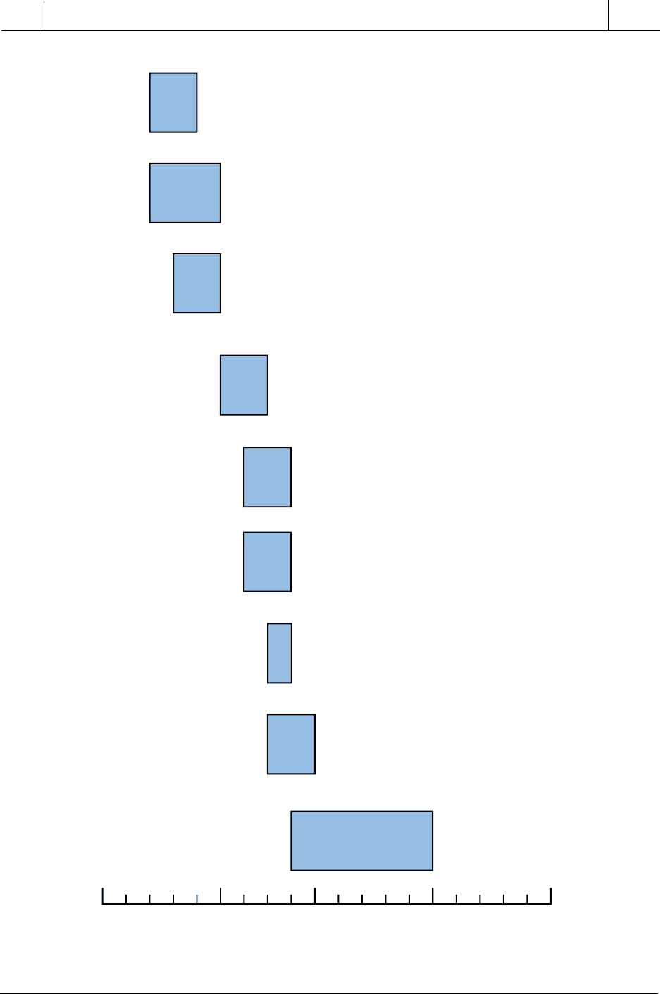
ducer/transmitter then sends a 4–20 mA signal to the PLC that is propor-
tional to the velocity of vibration in inches or meters per second. Figure 13-
37 shows vibration measuring devices that provide a 4–20 mA output.
Figure 13-37. (a) Vibration measuring devices and (b) the connection diagram for the
first device in part (a).
There are several guidelines for determining the level at which vibration
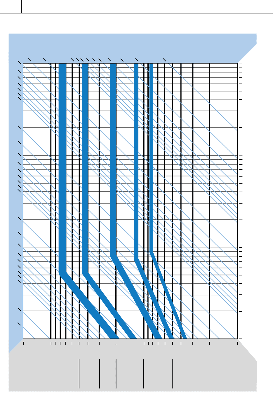
becomes critical. Figure 13-38 illustrates a vibration warning level guide
provided by PMC/BETA LP (Natick, MA), a vibration transducer manufac-
turer. A PLC can monitor the level of vibration in a machine or equipment and
provide the operator with a warning indication, according to the guide, before
damage occurs. Figure 13-39 illustrates a severity chart for machines with
vibration warning levels of 0.2–0.4 inches/sec over a frequency range of 100
to 100,000 rpm. This chart shows the variable peak-to-peak displacements for
Remote Reset
External
Equipment
Power
AC
Power
Shutdown Circuit
Alarm Circuit
Grounding Wire
7
6
5
4
3
2
1
Reset
Common
Shut
Down
Input
Power
8
9
10
11
12
13
14
Alarm
Analog
Common
External
Alarm
Power
Vibration
Level
Meter
4-20mA
Shielded Cable
(a)
(b)
Courtesy of PMC/BETA LP, Natick, MA
Courtesy of PMC/BETA LP, Natick, MA
605
CHAPTER
13
Data Measurements
and Transducers
Industrial Text & Video Company 1-800-752-8398
www.industrialtext.com
SECTION
4
PLC Process
Applications
Figure 13-38. Vibration warning level guide.
(Courtesy of PMC/BETA LP, Natick, MA)
1.0
0.5
0.1
0.05
0
Velocity (inches/sec)
0.2
0.3
0.2
0.2
0.4
0.2
0.4
0.3
0.1
0.05
• Machine tools
(unloaded)
• Turbines
• Gear boxes
• Pumps:
-gear
-centrifugal
• Electrical motors
• Compressors
(centrifugal)
• Fans/blowers
• Motor/generator sets
(electric driven)
• Hammermill
(unloaded)
• Conveyors
• Packaging
machinery
• Crushers
(unloaded)
• Engines
• Pumps
(reciprocating)
• Motor/generator sets
(engine driven)
• Compressors
(reciprocating)
Vibration Protection Levels
0.5
0.3
0.7
0.5 0.5
0.8
0.8
0.6
Typical vibration trip levels are shown for different types of machinery.
These trigger limits are recommended starting points for setting vibration
warning levels, defined as levels at which abnormal wear occurs.
These ranges are typical. Each machine will have its own personality
depending on how it is loaded, the particular installation, and the tolerances
of the machine itself.
606
SECTION
4
PLC Process
Applications
Industrial Text & Video Company 1-800-752-8398
www.industrialtext.com
CHAPTER
13
Data Measurements
and Transducers
Figure 13-39. Vibration severity chart.
(Courtesy of PMC/BETA LP, Natick, MA)
1
2
0.8
0.6
0.5
0.4
0.3
0.2
0.02
0.01
Velocity Limits
Very Rough
Danger of
oil film
breakdown
(shutdown)
Rough
Causes major
wear
Good
Minor faults
Smooth
Normal for
new equipment
Fair
Correct to
save wear
Velocity–Inches/Sec (Peak)
100 200 500 1000
2000 10,000
20,000 50,000 100,000
5,000
RPM
200
100
70
60
50
40
30
20
10
8
6
5
4
3
2
1
0.8
0.7
0.6
0.5
0.4
0.3
0.2
0.1
0.09
0.07
0.06
0.05
0.04
0.03
0.02
0.01
0.1
0.07
0.06
0.05
0.04
0.03
Very Bad
Bad
Fair
Good
Excellent
Displacement–Mils (Peak To Peak)
607
CHAPTER
13
Data Measurements
and Transducers
Industrial Text & Video Company 1-800-752-8398
www.industrialtext.com
SECTION
4
PLC Process
Applications
smooth to very rough severity and indicates possible consequences (bold
blue lines indicating very bad, bad, fair, etc.). For machines with higher or
lower warning levels, the limits shown on the vibration severity chart should
be increased or decreased, respectively.
If the vibration velocity surpasses the maximum allowable limit in a
vibration monitoring system, the PLC can annunciate an alarm condition
and initiate a shutdown of the system before a catastrophic failure occurs.
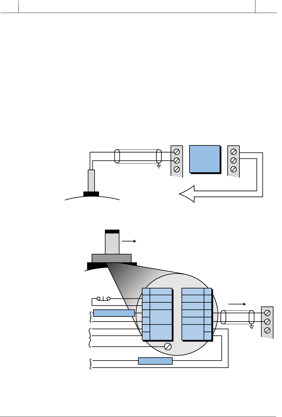
Figure 13-40 illustrates a typical direct interface application of a vibration
transducer (4–20 mA) to a PLC system where the PLC is responsible for a
shutdown command to the machine, if necessary. A vibration transducer/
Figure 13-40. Vibration transducers used in a PLC system to (a) control a shutdown
command and (b) monitor vibration levels.
To PLC
Remote Reset
External
Equipment
Power
AC
Power
Alarm
Power
Machine Circuit
Alarm Circuit
Grounding Wire
7
6
5
4
3
2
1
Reset
Common
Shut
Down
Input
Power
8
9
10
11
12
13
14
Alarm
Analog
Common
4–20 mA
Analog
Input
Discrete
Outputs
4–20 mA
Analog
Input
Monitors
Input Levels
of Vibration
To PLC
Transducer/Transmitter
(b) Digital signal to annunciate working levels of vibration.
(a) Digital signal to control a shutdown if vibration limit exceeds the max level.
PLC
System
Vibration
Transducer
Machine
Machine
4–20 mA
(a) Digital signal controls a shutdown if the vibration limit exceeds the maximum level.
(b) Digital signal annunciates working levels of vibration.

608
SECTION
4
PLC Process
Applications
Industrial Text & Video Company 1-800-752-8398
www.industrialtext.com
CHAPTER
13
Data Measurements
and Transducers
transmitter combination can also be interfaced with a programmable control-
ler to monitor vibration. The internal contacts of the transmitter can then be
used to shut down the machine or system if the vibration level surpasses the
specified alarm limits.
13-9 SUMMARY
In this chapter, we introduced basic measurement concepts that explain how
data and errors are interpreted and analyzed. This information, which is
based on statistical analysis, is very helpful when implementing an intelligent
or knowledge-based PLC system.
We also explained different techniques used to transform the physical
measurement of a transducer sensor into a voltage or current signal. Trans-
ducers, in general, are composed of several intermediate measurement and
connection elements, which vary depending on the type of transducer—
thermal, displacement, pressure, or flow. Process control systems, which we
will discuss next, use these devices to monitor system variables.
bridge circuit
Bourdon tube
displacement transducer
flow transducer
guarantee error
linear variable differential transformer (LVDT)
load cells
mean
median
mode
orifice plate
potentiometer
pressure transducer
propagation error
resistance temperature detector (RTD)
standard deviation
strain gauge
thermal transducer
thermistor
thermocouple
thermopile
turbine flow meter
Venturi tube
vibration transducer
KEY
TERMS
