Brizard A. An Introduction to Lagrangian Mechanics
Подождите немного. Документ загружается.

1.3. BRACHISTOCHRONE PROBLEM 15
=
Γ
i|jk
dx
j
dt
dx
k
dt
,
using the definition of the Christoffel symb ol
Γ
`
jk
= g
`i
Γ
i|jk
=
g
`i
2
∂g
ij
∂x
k
+
∂g
ik
∂x
j
−
∂
g
jk
∂x
i
!
,
where
g
ij
= n
−2
g
ij
denotes components of the inverse metric (i.e., g
ij
g
jk
= δ
i
k
), and its
symmetry property with resp ect to interchange of its two covariant indices (j ↔ k). Hence,
the variation δT
AB
can be expressed as
δT
AB
=
Z
t
B
t
A
"
d
2
x
i
dt
2
+ Γ
i
jk
dx
j
dt
dx
k
dt
#
g
i`
δx
`
dt
c
2
. (1.26)
We, therefore, find that the light path x(t) is a solution of the geodesic equation
d
2
x
i
dt
2
+ Γ
i
jk
dx
j
dt
dx
k
dt
=0, (1.27)
which is also the path of least time for which δT
AB
=0.
1.2.4 Eikonal Representation
Lastly, the index of refraction itself (for an isotropic medium) can be written as
n = |∇S| =
ck
ω
or ∇S = n
dx
ds
=
c k
ω
, (1.28)
where S is called the eikonal function and the phase speed of a light wave is ω/k; note that
the surface S(x, y, z)=constant represents a wave-front, which is complementary to the
ray picture used so far. To show that this definition is consistent with Eq. (1.20), we easily
check that
d
ds
n
dx
ds
!
=
d∇S
ds
=
dx
ds
· ∇∇S =
∇S
n
· ∇∇S =
1
2n
∇|∇S|
2
= ∇n.
This definition, therefore, implies that ∇× k = 0 (since ∇× ∇S = 0), where we used the
fact that the frequency of a wave is unchanged by refraction.
1.3 Brachistochrone Problem
The brachistochrone problem is another least-time problem and was first solved in 1696 by
Johann Bernoulli (1667-1748). The problem can be stated as follows. A bead is released
16 CHAPTER 1. INTRODUCTION TO THE CALCULUS OF VARIATIONS
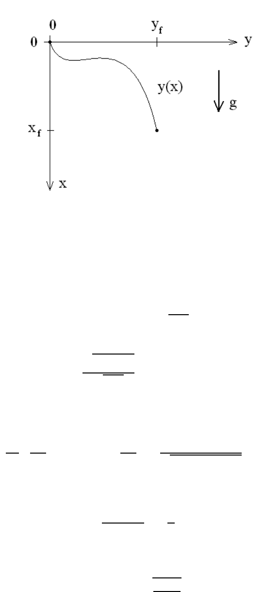
Figure 1.7: Brachistrochrone problem
from rest and slides down a frictionless wire that connects the origin to a given point (x
f
,y
f
);
see Figure 1.7. The question posed by the brachistochrone problem is to determine the
shape y(x) of the wire for which the descent of the bead under gravity takes the shortest
amount of time. Using the (x, y)-coordinates shown above, the speed of the bead after it has
fallen a vertical distance x along the wire is v =
√
2gx(where g denotes the gravitational
acceleration) and, thus, the time integral
T [y]=
Z
x
f
0
q
1+(y
0
)
2
√
2 gx
dx =
Z
x
f
0
F (y,y
0
,x) dx, (1.29)
is a functional of the path y(x). Since the integrand of Eq. (1.29) is independent of the
y-co ordinate ( ∂F/∂y = 0), the Euler’s First Equation (1.5) simply yields
d
dx
∂F
∂y
0
!
=0 →
∂F
∂y
0
=
y
0
q
2 gx [1 + (y
0
)
2
]
= α,
where α is a constant, which leads to
(y
0
)
2
1+(y
0
)
2
=
x
a
,
where a =(2α
2
g)
−1
is a scale length for the problem. Integration by quadrature yields the
integral solution
y(x)=
Z
x
0
s
η
a − η
dη,
1.3. BRACHISTOCHRONE PROBLEM 17
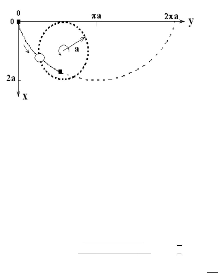
Figure 1.8: Brachistochrone solution
subject to the initial condition y(x = 0) = 0. Using the trigonometric substitution
η =2a sin
2
(θ/2) = a (1 − cos θ),
we obtain the parametric solution
x(θ)=a (1 − cos θ) and y(θ)=a (θ − sin θ). (1.30)
This solution yields a parametric representation of the cycloid (Figure 1.8) where the bead
is placed on a rolling hoop of radius a. Lastly, the time integral (1.29) for the cycloid
solution (1.30) is
T
cycloid
(Θ) =
Z
Θ
0
q
(dx/dθ)
2
+(dy/dθ)
2
dθ
q
2ga(1 − cos θ)
=Θ
s
a
g
.
In particular, the time needed to reach the bottom of the cycloid (Θ = π)isπ
q
a/g.
18 CHAPTER 1. INTRODUCTION TO THE CALCULUS OF VARIATIONS
1.4 Problems
Problem 1
According to the Calculus of Variations, the straight line y(x)=mx between the two
points (0, 0) and (1,m) on the (x, y)-plane yields a minimum value for the length integral
L[y]=
Z
1
0
q
1+(y
0
)
2
dx,
since the path y(x)=mx satisfies the Euler equation
0=
d
dx
y
0
q
1+(y
0
)
2
=
y
00
[1 + (y
0
)
2
]
3/2
.
By choosing the path variation δy(x)=x(x −1), which vanishes at x = 0 and 1, we find
L[y + δy]=
Z
1
0
q
1+[2x+(m − )]
2
dx =
1
2
Z
tan
−
1
(m+)
tan
−1
(m−)
sec
3
θdθ.
Evaluate L[y + δy] explicitly as a function of m and and show that it has a minimum in
at =0.
Problem 2
Prove the identities (1.16).
Problem 3
A light ray travels in a medium with refractive index
n(y)=n
0
exp (−βy),
where n
0
is the refractive index at y = 0 and β is a positive constant.
(a) Use the results of the Principle of Least Time contained in the Notes distributed in
class to show that the path of the light ray is expressed as
y(x; β)=
1
β
ln
"
cos(βx− φ
0
)
cos φ
0
#
, (1.31)
where the light ray is initially travelling upwards from (x, y)=(0, 0) at an angle φ
0
.
(b) Using the appropriate mathematical techniques, show that we recover the expected
result
lim
β→0
y(x; β) = (tan φ
0
) x

1.4. PROBLEMS 19
from Eq. (1.31).
(c) The light ray reaches a maximum height y at x = x(β), where y
0
(x; β) = 0. Find
expressions for
x and y(β)=y(x; β).
20 CHAPTER 1. INTRODUCTION TO THE CALCULUS OF VARIATIONS
Chapter 2
Lagrangian Mechanics
2.1 Maupertuis-Jacobi Principle of Least Action
The publication of Fermat’s Principle of Least Time in 1657 generated an intense contro-
versy between Fermat and disciples of Ren´e Descartes (1596-1650) involving whether light
travels slower (Fermat) or faster (Descartes) in a dense medium as compared to free space.
In 1740, Pierre Louis Moreau de Maupertuis (1698-1759) stated (without proof) that,
in analogy with Fermat’s Principle of Least Time for light, a particle of mass m under
the influence of a force F moves along a path which satisfies the Principle of Least Action:
δS = 0, where the action integral is defined as
S =
Z
p · dx =
Z
mv ds, (2.1)
where v = ds/dt denotes the magnitude of particle velocity, which can also be expressed as
v =
q
2
m
(E − U), with the particle’s kinetic energy K written in terms of its total energy
E and its potential energy U.
In 1744, Euler proved the Principle of Least Action δ
R
mv ds = 0 for particle motion
in the (x, y)-plane as follows. For this purpose, we use the Frenet-Serret curvature formula
for the path y(x); here, we define the tangent unit vector
b
v and the principal normal unit
vector
b
n as
b
v =
dx
ds
=
b
x + y
0
b
y
q
1+(y
0
)
2
and
b
n =
y
0
b
x −
b
y
q
1+(y
0
)
2
, (2.2)
where y
0
= dy/dx and ds = dx
q
1+(y
0
)
2
. The Frenet-Serret formula for the curvature of
a two-dimensional curve is
d
b
v
ds
=
|y
00
|
b
n
[1 + (y
0
)
2
]
3/2
= κ
b
n,
21
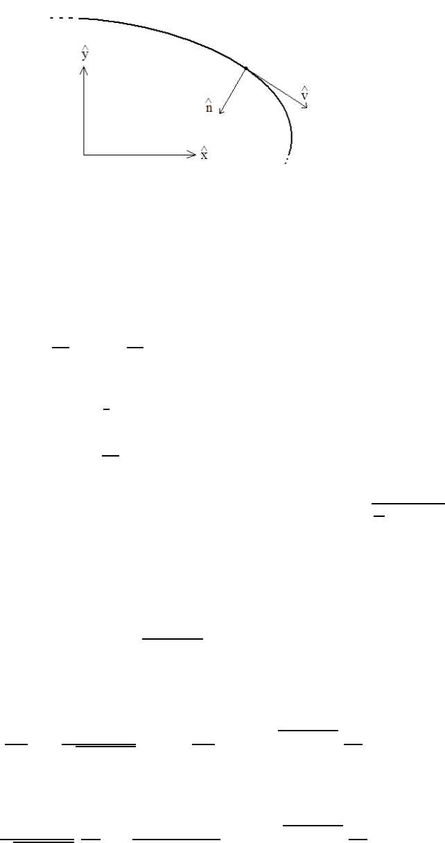
22 CHAPTER 2. LAGRANGIAN MECHANICS
Figure 2.1: Frenet-Serret frame
where the instantaneous radius of curvature ρ is defined as ρ = κ
−1
(see Figure 2.1). First,
by using Newton’s Second Law of Motion and the Energy conservation law, we find the
relation
F = mv
dv
ds
b
v + v
d
b
v
ds
!
=
b
v (
b
v · ∇K)+mv
2
κ
b
n = ∇K (2.3)
between the unit vectors
b
v and
b
n associated with the path, the Frenet-Serret curvature
κ, and the kinetic energy K =
1
2
mv
2
(x, y) of the particle. Note that Eq. (2.3) can be
re-written as
d
b
v
ds
=
b
v × (∇ln v ×
b
v) , (2.4)
which hightlights a deep connection with Eq. (1.20) derived from Fermat’s Principle of
Least Time, where the index of refraction n is now replaced by v =
q
2
m
(E − U). Lastly,
we point out that the type of dissipationless forces considered in Eq. (2.3) involves active
forces (defined as forces that do work), as opp osed to passive forces (defined as forces that
do no work, such as constraint forces).
Next, the action integral (2.1) is expressed as
S =
Z
mv(x, y)
q
1+(y
0
)
2
dx =
Z
F (y, y
0
; x) dx, (2.5)
so that the Euler’s First Equation (1.5) corresponding to Maupertuis’ action integral (2.5),
with
∂F
∂y
0
=
mv y
0
q
1+(y
0
)
2
and
∂F
∂y
= m
q
1+(y
0
)
2
∂v
∂y
,
yields the Maupertuis-Euler equation
my
0
q
1+(y
0
)
2
∂v
∂x
+
my
00
[1 + (y
0
)
2
]
3/2
= m
q
1+(y
0
)
2
∂v
∂y
. (2.6)
2.2. PRINCIPLE OF LEAST ACTION OF EULER AND LAGRANGE 23
Using the relation F = ∇K and the Frenet-Serret formulas (2.2), the Maupertuis-Euler
equation (2.6) b ecomes
mv
2
κ = F ·
b
n,
from which we recover Newton’s Second Law (2.3).
Carl Gustav Jacobi (1804-1851) emphasized the connection between Fermat’s Principle
of Least Time (1.1) and Maupertuis’ Principle of Least Action (2.1) by introducing a
different form of the Principle of Least Action δS = 0, where Jacobi’s action integral is
S =
Z
q
2m (E − U) ds =2
Z
K dt, (2.7)
where particle momentum is written as p =
q
2m (E −U). To obtain the second expression
of Jacobi’s action integral (2.7), Jacobi made use of the fact that, by introducing a path
parameter τ such that v = ds/dt = s
0
/t
0
(where a prime here denotes a τ-derivative), we
find
K =
m (s
0
)
2
2(t
0
)
2
= E − U,
so that
2 Kt
0
= s
0
q
2m (E − U) ,
and the second form of Jacobi’s action integral results. Jacobi used the Principle of Least
Action (2.7) to establish the geometric foundations of particle mechanics. Here, the Euler-
Jacobi equation resulting from Jacobi’s Principle of Least Action is expressed as
d
ds
√
E − U
dx
ds
!
= ∇
√
E − U,
which is identical in form to the light-curvature equation (1.20).
2.2 Principle of Least Action of Euler and Lagrange
2.2.1 Generalized Coordinates in Configuration Space
The configuration of a mechanical system with constraints evolving in n-dimensional space,
with spatial coordinates x =(x
1
,x
2
, ..., x
n
), can sometimes be described in terms of general-
ized coordinates q =(q
1
,q
2
, ..., q
k
)inak-dimensional configuration space, with k ≤ n.For
example, for a mechanical system composed of two particles (see Figure 2.2), with masses
(m
1
,m
2
) and three-dimensional coordinate positions (x
1
, x
2
), tied together with a mass-
less ro d (so that the distance |x
1
− x
2
| is constant), the configuration of this two-particle
system can b e described in terms of the coordinates x
CM
=(m
1
x
1
+ m
2
x
2
)/(m
1
+ m
2
)
of the center-of-mass (CM) in the Laboratory frame (O) and the orientation of the rod in
the CM frame (O’) expressed in terms of the two angles ( θ, ϕ). Hence, as a result of the
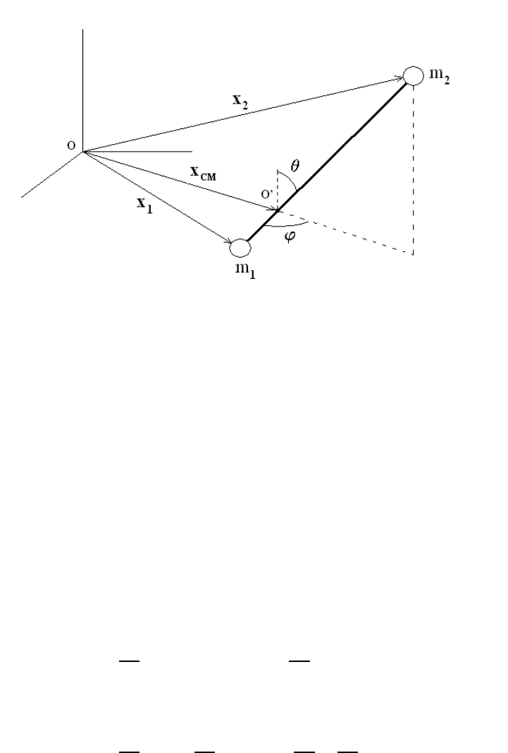
24 CHAPTER 2. LAGRANGIAN MECHANICS
Figure 2.2: Configuration space
existence of a single constraint, the generalized coordinates for this system are (x
CM
; θ, ϕ)
and we have reduced the number of coordinates needed to describe the state of the system
from six to five.
2.2.2 Constrained Motion on a Surface
The general problem associated with the motion of a particle constrained to move on a
surface described by the relation F (x, y, z) = 0 is described as follows. First, since the
velocity dx/dt of the particle along its trajectory must be perpendicular to the gradient
∇F , we find that dx · ∇ F = 0. Next, any point x on the surface F (x, y, z)=0maybe
parametrized by two surface coordinates (u, v) such that
∂x
∂u
(u, v) · ∇F =0=
∂x
∂v
(u, v) · ∇F.
Hence, we may write
dx =
∂x
∂u
du +
∂x
∂v
dv and
∂x
∂u
×
∂x
∂v
= J∇F,
where the function J dep ends on the surface coordinates (u, v). It is, thus, quite clear that
the surface coordinates (u, v) are the generalized coordinates for this constrained motion.
For example, we consider the motion of a particle constrained to move on the surface
of a cone of apex angle α. Here, the constraint is expressed as F(x, y, z)=r −z tan α =0