Brigatti M.F., Galan E. and Theng B.K.G. Structures and mineralogy of clay minerals
Подождите немного. Документ загружается.

Handbook of Clay Science
Edited by F. Bergaya, B.K.G. Theng and G. Lagaly
Developments in Clay Science, Vol. 1
r 2006 Elsevier Ltd. All rights reserved.
19
Chapter 2
STRUCTURES AND MINERALOGY OF CLAY MINERALS
M.F. BRIGATTI
a
, E. GALAN
b
AND B.K.G. THENG
c
a
Dipartimento di Scienze della Terra, Universita
`
di Modena, I-41100 Modena, Italy
b
Departamento de Cristalografı
´
a, Mineralogı
´
a y Quı
´
mica Agrı
´
cola, Facultad de
Quı
´
mica, Universidad de Sevilla, ES-41071 Sevilla, Spain
c
Landcare Research, Palmerston North, New Zealand
2.1. GENERAL STRUCTURAL INFORMATION
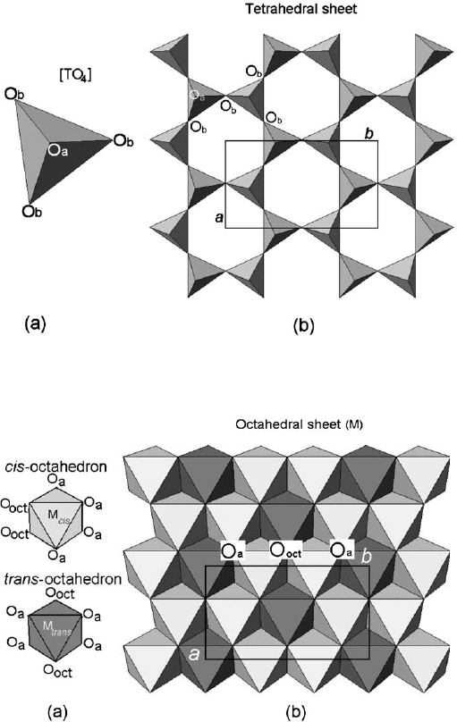
Phyllosilicates considered in this section ideally contain a continuous tetrahedral
sheet. Each tetrahedron consists of a cation, T, coordinated to four oxygen atoms, and
linked to adjacent tetrahedra by sharing three corners (the basal oxygen atoms, O
b
)to
form an infinite two-dimensional ‘hexagonal’ mesh pattern along the a, b crystallo-
graphic directions (Fig. 2.1). In the octahedral sheet, connections between each oc-
tahedron, M, to neighbouring octahedra are made by sharing edges. The edge-shared
octahedra form sheets of hexagonal or pseudo-hexagonal symmetry (Fig. 2.2). Com-
mon tetrahedral cations are Si
4+
,Al
3+
,andFe
3+
. Octahedral cations are usually
Al
3+
,Fe
3+
,Mg
2+
,andFe
2+
, but other cations, such as Li
+
,Mn
2+
,Co
2+
,Ni
2+
,
Cu
2+
,Zn
2+
,V
3+
,Cr
3+
,andTi
4+
were identified. Octahedra show two different
topologies related to (OH) position, i.e., the cis- and the trans-orientation (Fig. 2.2).
The free corners (the tetrahedral apical oxygen atoms , O
a
) of all tetrahedra point
to the same side of the sheet and co nnect the tetrahedral and octahedral sheets to
form a common plane with octahedral anionic position O
oct
(O
oct
¼ OH, F, Cl, O)
(Fig. 2.3). O
oct
anions lie near to the centre of each tetrahedral 6-fold ring, but are
not shared with tetrahedra. The 1:1 layer structure consists of the repetition of one
tetrahedral and one octahedral sheet, while in the 2:1 layer structure one octahedral
sheet is sandwiched between two tetrahedral sheets (Fig. 2.3).
In the 1:1 layer structure, the unit cell includes six octahedral sites (i.e., four cis-
and two trans-oriented octahedral) and four tetrahedral sites. Six octahedral sites
and eight tetrahedral sites characterize the 2:1 layer unit cell. Structures with all the
six octahedral sites occupied are known as trioctahedral (Fig. 2.4a). If only four of
the six octahedra are occupied, the structure is referred to as dioctahedral (Fig. 2.4b ).
The structural formula is often reported on the basis of the half unit-cell content, i.e.,
it is based on three octahedral sites.
DOI: 10.1016/S1572-4352(05)01002-0
In the 1:1 or TM phyllosilicates (e.g., dioctahedral kaolinite and trioctahedral ser-
pentine) each layer is about 0.7 nm thick (Fig. 2.5a). One surface of the layer consists
entirely of oxygen atoms (O
b
) belonging to the tetrahedral sheet, while the other surface
is composed of O
oct
(mostly OH groups) from the octahedral sheet (Fig. 2.3). In the 2:1
or TMT layer the tetrahedral sheets are inverted and two-thirds of the octahedral
Fig. 2.2. (a) O
oct
(OH, F, Cl) orientation in cis-octahedron and trans-octahedron; (b) location
of cis- and trans-sites in the octahedral sheet. O
a
and O
b
refer to apical and basal oxygen
atoms, respectively.aand b refer to unit cell parameters.
Fig. 2.1. (a) Tetrahedron [TO
4
]; (b) tetrahedral sheet. O
a
and O
b
refer to apical and basal
oxygen atoms, respectively. a and b refer to unit-cell parameters.
Chapter 2: Structures and Mineralogy of Clay Minerals20
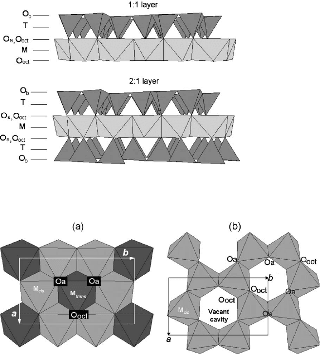
hydroxyl groups are replaced by tetrahedral apical oxygen atoms (Fig. 2.3). Both
surfaces of such a layer consist of tetrahedral basal oxygen atoms O
b
. The periodicity
along the c-axis varies from 0.91–0.95 nm in talc and pyrophyllite (Fig. 2.5b)to
1.40–1.45 nm in chlorite (Fig. 2.5e). The higher values for chlorite are due to interlayer
occupancy. In talc, the interlayer space is empty, whereas in mica and illite (Fig. 2.5c)it
is occupied by anhydrous alkaline and alkaline-earth cations (layer periodicity
E1.0 nm). The interlayer space of smectite and vermiculite (Fig. 2.5d) contains alka-
line or alkaline-earth cations together with water molecules (layer periodicity is about
Fig. 2.3. Models of a 1:1 and 2:1 layer structure. O
a
,O
b
, and O
oct
refer to tetrahedral basal,
tetrahedral apical, and octahedral anionic position, respectively. M and T indicate the oc-
tahedral and tetrahedral cation, respectively.
Fig. 2.4. (a) trioctahedral sheet; (b) dioctahedral sheet. O
a
represents the apical oxygen atoms
shared with tetrahedra, and O
oct
is the anionic site shared between adjacent octahedra. a and b
are unit-cell parameters.
2.1. General Structural Information 21
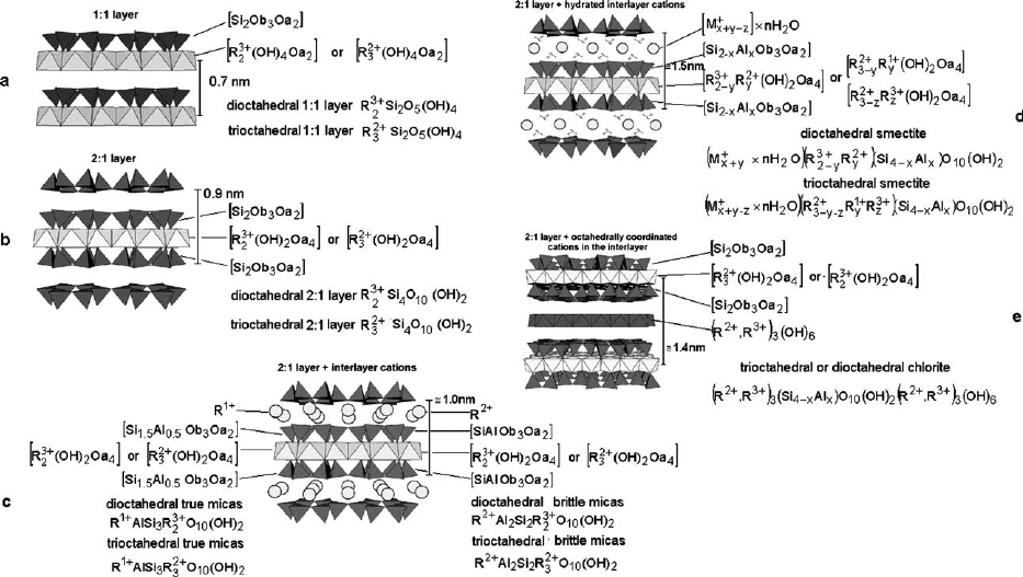
Fig. 2.5. Different layer structures: (a) 1:1 layer (i.e., kaolinite- and serpentine-like layer); (b) 2:1 layer (i.e., pyrophillite- and talc-like
layer); (c) 2:1 layer with anhydrous interlayer cations (i.e., the mica-like layer); (d) 2:1 layer with hydrated interlayer cations (i.e.,
smectite- and vermiculite-like layer); (e) 2:1 layer with octahedrally coordinated interlayer cations (i.e., chlorite-like layer).
Chapter 2: Structures and Mineralogy of Clay Minerals22
1.2 nm when the interlayer position is occupied by cations with low-field strength and
water molecules, about 1.5 nm when the interlayer is occupied by high-field strength
cations and water molecules, and more than 1.5 nm when water molecules are ex-
changed by different polar molecules). On the contrary, in chlorite (Fig. 2.5e)the
interlayer is occupied by a continuous octahedral sheet, thus showing a TMTM
int
sequence (where M
int
is the octahedral interlayer sheet).
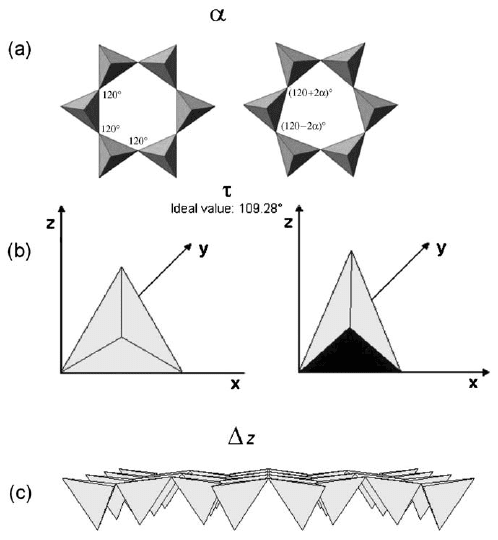
The lateral dimension of the tetrahedral sheet is usually greater than that of the
octahedral sheet. The lateral misfit between the two sheets requires an adjustment
in one or both sheets, causing the layer structure to deviate from ideal hexagonal
symmetry. Layer distortion, following from the matching of tetrahedral and
octahedral lateral dimensions, usually follows three different mechanisms: (i) the ro-
tation of adjacent tetrahedral as evaluated by the angle a (i.e., the deviation from 1201
of each angle in the ring (Fig. 2.6a); (ii) the increase in thickness of the tetrahedral
sheet, thereby reducing the basal area of each tetrahedron as evaluated by the angle t
(i.e., the deviation from 109128
0
of O
a
–T–O
b
triads, Fig. 2.6b); and (iii) the tilting of
the tetrahedral basal oxygen plane as evaluated by the Dz parameter (Fig. 2.6c). More
Fig. 2.6. Individual tetrahedra and tetrahedral sheet adjustments in order to accommodate
the tetrahedral sheet to the octahedral sheet. (a) tetrahedral ring rotation, a parameter; (b)
tetrahedral flattening, t parameter; (c) tetrahedral tilting, Dz parameter.
2.1. General Structural Information 23
details are provided by Brindley and Brown (1980), Bailey (1988a), de la Calle and
Suquet (1988), Evans and Guggenheim (1988), Giese (1988), Gu
¨
ven (1988), Wicks
and O’Hanley (1988), Moore and Reynolds (1989), Brigatti and Guggenheim (2002).
2.2. LAYER CHARGE (X)
When the tetrahedral and octahedral sheets are joined in a layer, the resulting
structure can be either electrically neutral or negatively charged. Electrical neutrality
exists if (i) the octahedral sheet contains trivalent cations (R
3+
) in two octahedral
sites (usually Al
3+
and Fe
3+
), with a vacancy (&) in the third octahedron
[R
3þ
2
(OH)
6
]; (ii) divalent cations (R
2+
, usually Fe
2+
,Mg
2+
,Mn
2+
) occupy all the
octahedral sites [R
2þ
3
(OH)
6
]; and (iii) the tetrahedral sheet contains Si
4+
in all tet-
rahedra. A negative layer charge arises from (i) substitution of Al
3+
for Si
4+
in
tetrahedral sites; (ii) substitution of Al
3+
or Mg
2+
for lower charge cations in oc-
tahedral sites, and (iii) the presence of vacancies. This charge variability is recognized
as one of the most important features of 2:1 phyllosilicates and micas, because it
induces occupancy of the interlayer space by exchangeable cations. In 2:1 phyllo-
silicates the (negative) layer charge ranges from 0.2 in montmorillonite and hectorite
to 2.0 in brittle micas, calculated on the basis of their structural formulae (i.e., half
unit-cell content). In 1:1 phyllosilicates the layer charge is usually close to zero.
2.3. POLYTYPISM
A compound is polytypic if it occurs in several different structural modifications
for which layers of identical structure and composition are stacked in different ways.
In a polytypic series the two-dimensional translations within the layers are (essen-
tially) preserved . The periodicity normal to the layers varies between polytypes ac-
cording to the number of layers involved in the stacking sequence. Thus, small
deviations from stoichiometry (up to 0.20 atoms per formula unit) within a same
polytypic series are admissible in the case of phyllosilicates. The theoretical prin-
ciples of polytypism have been reviewed by Baronnet (1978), Bailey (1988a), Takeda
and Ross (1995), D
ˇ
urovic
ˇ
(1997, 1999), and Nespolo et al. (1997) and will not be
further discussed. Polytypism will only be mention ed when we describe relevant
features of clay mineral structures .
2.4. MIXED-LAYER STRUCTURES
Mixed-layer phyllosilicates or interstratified phyllosilicates can be built up by two or
more different components. Structures with more than two components are less com-
mon, possibly because it is difficult to recognize all the different layers. Interstratified
clay minerals can have (i) ordered or regular mixed-layer structures if different layers
Chapter 2: Structures and Mineralogy of Clay Minerals24
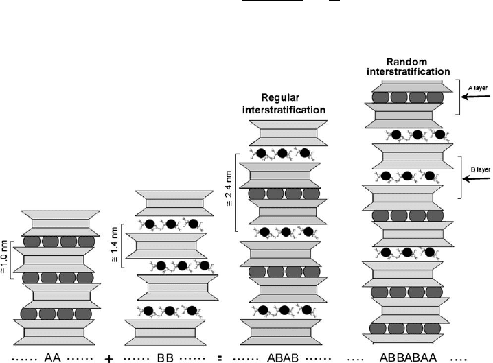
alternate along the c* direction in a periodic pattern (e.g., the stacking of generic type
A and type B layers can be y ABABAB y or y AABAABAA y or y AAA-
ABAAAABAAAAB y etc.) and (ii) disordered or irregular mixed-layer structures, if
the stacking along the c* direction of type A and B layers is random (e.g., y AB-
BABAA y or y AAABABBAAAAABABA y). Fig. 2.7 shows an example of in-
terstratification between 2:1 anhydrous layers with periodicity of about 1 nm and 2:1
hydrated layers with periodicity of about 1.4 nm. Regular sequences are identified by
special names. For example, the name ‘rectorite’ is attributed to a regular interstrat-
ification of dioctahedral mica and dioctahedral smectite; ‘tosudite’ is a regular inter-
stratification of dioctahedral chlorite and dioctahedral smectite; ‘corrensite’ represents
a regular interstratification of trioctahedral vermiculite with trioctahedral chlorite;
‘aliettite’ is a regular interstratification of talc and trioctahedral smectite (saponite or
vermiculite) (Bailey, 1982). The criterion adopted by the AIPEA Nomenclature Com-
mittee to attribute special names to regular 1:1 interstratification is that the sequence
gives rational reflections. A test of rationality for the diffraction pattern is provided by
calculating the coefficient of variability (CV) applied to at least ten 00l reflections
CV ¼ 100
X
n
i¼1
X
i
X
2
ðn 1Þ
"#
1=2
1
X
where X
i
¼ l d
(001)
and
X ¼
P
n
i¼1
X
i
=n) o0.75 (Bailey, 1982)
Fig. 2.7. Regularly and randomly interstratified phyllosilicates. A and B are layers with
different periodicity along the c direction.
2.4. Mixed-Layer Structures 25
If a two-component type having different d(001) periodicity is randomly interstrat-
ified, the mineral is identified by using the name of the components such as illite–smec-
tite, illite–chlorite, illite–vermiculite, and kaolinite–smectite. In randomly stacked mixed
layer structures, layer sequence can be ‘completely different’. Examples are the irregular
stacking of (i) illite (1 nm) and smectite (1.4 nm), (ii) integral multiples of serpentine
(0.7 nm) and chlorite (1.4 nm), or (iii) layers with similar basal spacing but with differ-
ent local structure such as the random stacking of trans-vacant and cis-vacant illite
layers (Drits, 1997). A ‘completely different’ d
(001)
distance is measured by X-ray
diffraction (XRD). The basal reflections d(00l) form a succession that does not cor-
respond to a series of rational and integral values of l indices. This deviation from the
Bragg rule arises from the random variation of the basal periodicity along c* and can
be a good criterion to identify the presence of irregular interstratified structures (Drits
and Tchoubar, 1990). When the interstratified material is made up from sequences of
different layers with the same thickness, or a thickness that is an integer multiple of the
other (e.g., chlorite–serpentine), the XRD pattern looks like that of a regular phase.
Recognition of the interstratified character of a sequence requires a precise anal-
ysis of the position intensity and of the profile width of basal reflections, in con-
junction with high-resolution transmission electron microscopy (HRTEM) (Moore
and Reynolds, 1989; Banfield and Bailey, 1996). Finally, the analysis of XRD pat-
terns can provide useful guidance even in the case of equal layer distance of the
component. For example, the sequence of cis-andtrans-vacant sites in adjacent illite
layers, produces displacements along the a direction, yielding d(110) reflections that
violate the individual layer symmetry.
Useful references to the application of statistical methods to the interpretation
and prediction of interstratified mineral structures have been provided by Nadeau
et al. (1984, 1985), Reynolds (1988), Drits and Tchoubar (1990), Baronnet (1992),
Veblen (1992), and Drits (1997).
2.5. THE 1:1 LAYER
2.5.1. Dioctahedral 1:1 Minerals: The Kaolin Group
The clay minerals in the kaolin group consist of dioctahedral 1:1 layer structures
with a general composition of Al
2
Si
2
O
5
(OH)
4
. Kaolinite, dickite, and nacrite are
polytypes. The kaolinite stacking sequence consists of identical layers with an in-
terlayer shift of 2a/3. Dickite and nacrite have a two-layer stacking sequence where
the vacant site of the octahedral sheet alternates between two distinct sites (Brindley
and Brown, 1980). Halloysite is a hydrated polymorph of kaolinite with curved
layers and a basal spacing of 1 nm that decreases to about 0.7 nm on dehydration.
The composition of the kaolin group minerals is characterized by a predominance of
Al
3+
in octahedral sites, althoug h some isomorphous substitution of Mg
2+
,Fe
3+
,
Ti
4+
, and V
3+
for Al
3+
can occur.
Chapter 2: Structures and Mineralogy of Clay Minerals26
A. Kaolinite
Pauling (1930) was the first to outline the crystal structure of kaolinite using models
based on idealized polyhedra. Gruner (1932b) reported the first structural interpre-
tation of the kaolinite powder XRD pattern. He indicated that the mineral belonged
to the monoclinic Cc symmetry with d(001) ¼ 1.43 nm, corresponding to a two-layer
structure. This was subsequently confirmed by Hendricks (1938b). Brindley and
Robinson (1945, 1946) found that many reflections in the powder pattern could not
be indexed correctly on the basis of a monoclinic structure, and suggested a lowering
of layer symmetry to the triclinic C1. This symmetry is consistent with a 1:1 layer
structure built up by stacking of identical layers with a translation of a/3. Kaolinite,
dickite, and nacrite consist of sequences with different position of octahedral va-
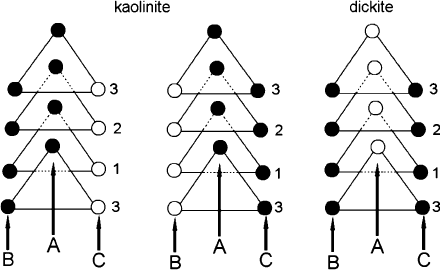
cancies in adjacent layers. Bailey (1963) has demonstrated that both kaolinite and
dickite have a 1M stacking sequence of layers. Octahedral site vacancies alternate in
dickite, whereas in kaolinite the location of the vacancy is the same in adjacent layers.
Three polytypes, all based on a 1M structure, are found for 1:1 dioctahedral phyllo-
silicates. The 1M structure presents three possible locations for the vacant octahedral
site, commonly referred as A, B, or C site vacancy (Adams, 1983; Thompson and
Withers, 1987; Bish and Von Dreele, 1989; Bukin et al., 1989; Smrc
ˇ
ok et al., 1990;
Bish, 1993). The structure is chiral if the vacant site is B or C, and achiral if the
vacant site is A. All naturally occurring kaolinites are chiral (Fig. 2.8).
Hobbs et al. (1997) have modelled the kaolinite structure by an all-atom ab initio
energy minimization method. Their results confirm the space group C1, and predict
significantly different Si–O bond lengths for the basal and apical tetrahedral oxygen
atoms. A low-temperature neutron powder diffraction study by Bish (1993) indicates
that low temperatures influence the interlayer separation but has little effect on tet-
rahedral and octahedral parameters. The structure refinement, derived by Neder et al.
(1999) from single-crystal synchrotron data, confirms the C1 symmetry and provides
Fig. 2.8. Projection on the (001) plane of the octahedral sites in kaolinite and dickite showing
the possible placement of the vacant octahedral site (open circles). Closed circles represent
Al
3+
octahedra. Modified after Bailey (1963).
2.5. The 1:1 Layer 27
the following unit-cell parameters: a ¼ 0.5154(9) nm, b ¼ 0.8942(4) nm, c ¼ 0.7401
(10) nm, a ¼ 91.69(9)1, b ¼ 104.61(5)1, and g ¼ 89.82(4)1. Except for the slight differ-
ence in b-angle, these values are very similar to those obtained by Bish and Von
Dreele (1989), using X-ray and neutron powder diffraction, i.e., a ¼ 0.5156(1) nm,
b ¼ 0.89446(2) nm, c ¼ 0.740485(2) nm, a ¼ 91.697(2)1, b ¼ 104.862(2)1, and g ¼
89.823(2)1. The refinement indicates that tetrahedra are significantly distorted with
the Si–O
a
bond shorter by 0.0013 nm than the average Si–O bond distances. On the
other hand, the octahedral Al–O
a
bonds are significantly longer than the Al–O
oct
(i.e.,
Al–OH) bonds.
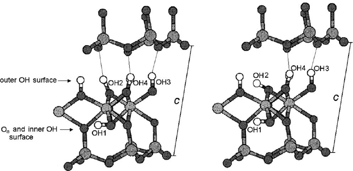
The interlayer OH vectors associated with H-bonding are nearly normal to (001),
forming three interlayer hydrogen bonds as shown in Fig. 2.9. Previous studies
generally agreed on the position of the Si, Al, and O atoms. However, some un-
certainties remain as to the position of the OH groups. The kaolinite layer is es-
sentially neutral and any two contiguous layers are linked through –Al–O–H
y
O–Si–
hydrogen bonding. The primitive unit cell contains four crystallographically distinct
O–H groups. Three of them (labelled OH
2
,OH
3
,OH
4
) are located at the inner
surface and one (labelled OH
1
) is inside the layer as shown in Fig. 2.9a. These
hydroxyl groups form strong hydrogen bonds if they are oriented nearly perpen-
dicular to the layer but are not involved in H-bonding if they are parallel to the layer
(Fig. 2.9). The extensive research into OH group orientation has been reviewed by
Giese (1988). The crystal structure refinement of a deuterated kaolinite (Akiba et al.,
1997) confirms that the three inner OD vectors point toward the tetrahedral sheet,
and form H-bonding with basal oxygen atoms of the adjacent kaolinite layer. One of
these three, however, differs from the other two in bond angle, thus, suggesting a
different orientation of the bond. Benco et al. (2001a–c) have exp lained interlayer
Fig. 2.9. Different OH orientations on the octahedral surface of kaolinite. Modified after
(Benco et al., 2001a).
Chapter 2: Structures and Mineralogy of Clay Minerals28