Becker W. Advanced Time-Correlated Single Photon Counting Techniques
Подождите немного. Документ загружается.

7.4 Generating the Synchronisation Signal 305
tuation and excellent power stability; diode requirements are moderate. For lasers
with pulse amplitude fluctuations, such as dye lasers, a photodiode should be used
that gives a pulse width below 1 ns and high linearity up to an output pulse current
of 10 mA. Small PIN diodes of 0.1 to 0.5 mm
2
active area usually perform best.
The pulse current,
I
peak
, obtained for a given average power, P
av
, and vice versa,
can be estimated by
pwrep
av
peak
tf
SP
I
or
S
tfI
P
pwreppeak
av
(7.7)
with f
rep
= pulse repetition rate, S = sensitivity of the diode in A/W, t
pw
= pulse
width delivered by the diode. The typical spectral sensitivity of a silicon photodi-
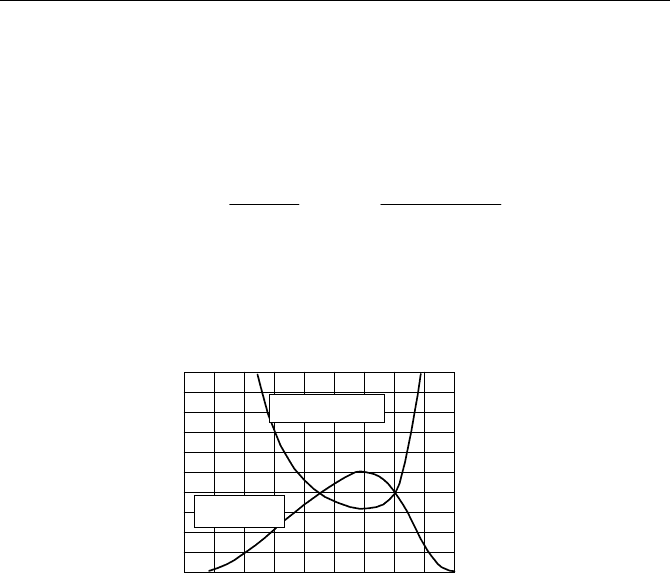
ode and the average laser power required to obtain a synchronisation signal of
100 mV (or 2 mA) peak amplitude are shown in Fig. 7.43.
0
0.1
0.2
0.3
0.4
0.5
0.6
0.7
0.8
0.9
1.0
Sensitivity of
Si Photodiode
Power for 100 mV
at 80 MHz
300 400 500 600 700 800 900 1000nm
Wavelength
0
0.1
0.2
0.3
0.4
0.5
0.6
0.7
0.8
0.9
1.0
Spectral
sensitivity
of
Si-PIN
photodiode
A/W
Power of
100 mV / 1ns
at 50 Ohm,
80 MHz laser
for
mW
Fig. 7.43 Sensitivity of a Si photodiode vs. wavelength and average laser power for 2 mA
peak current and 1 ns width at 80 MHz repetition rate
Figure 7.43 shows that a PIN photodiode is sufficient to obtain reference pulses
from a Ti:Sapphire laser or a frequency-doubled Nd:YAG laser. In most cases it is
sufficient to direct a reflection of the laser beam from a glass surface into the pho-
todiode. For dye lasers, focusing is required to obtain sufficient power on the
diode. Figure 7.43 shows that a PIN photodiode cannot reasonably be used to
generate a reference signal for a picosecond diode laser. Even if the laser is per-
fectly focused on the diode, almost the full power of the laser would be required to
obtain enough signal amplitude.
If the sensitivity of a simple PIN diode is too low, an avalanche diode (APD)
can be used. However, APDs have some drawbacks compared to simple PIN di-
odes. The most severe one is that the gain depends strongly on the operating volt-
age, and, more importantly, on the temperature. A good gain stability can only be
achieved if the diode is temperature-stabilised or the supply voltage is regulated
by the temperature. Moreover, the signal-to-noise ratio decreases if an avalanche
photodiode is operated close to its maximum stable gain. To keep gain variations
and noise negligible, a gain of 50 should not be exceeded.
Si photodiodes have a poor sensitivity in the UV range. UV-enhanced Si PIN
photodiodes are available, but usually do not perform well at short pulses. In fre-
306 7 Practice of TCSPC Experiments
quency-multiplied Ti:Sapphire systems the reference photodiode should therefore
be illuminated by light at the fundamental wavelength of the laser. At this wave-
length a photodiode has the best sensitivity, and possible intensity fluctuations are
smaller than in the SHG or THG. If UV operation cannot be avoided, a possible
solution are Silicon Carbide or Silicon Nitride diodes.
The minimum pulse width delivered by a PIN or avalanche photodiode is given
by the product of the junction capacitance, Cj, and the load resistance of 50 Ohm.
A small Cj is achieved only if the „I“ region of a PIN diode or the avalanche re-
gion of an APD is fully depleted. This requires PIN diodes to be operated close to
their maximum permissible reverse voltage. APDs should be used at 30% or more
of their breakdown voltage.
Various complete photodiode modules are commercially available. They use Si
PIN photodiodes at an internally generated reverse voltage in the range of 30 V, Si
avalanche photodiodes at a voltage of 50 to 150 V, or fast InGaAs diodes.
In some extreme cases the sensitivity even of an avalanche photodiode is too
low to obtain a reasonable reference signal. This can happen in the case of excita-
tion by nanosecond flashlamps or synchrotron radiation, or for experiments on
electrical discharges or sonoluminescence. In these cases a PMT must be used to
generate the reference signal. The PMT is operated at a gain considerably lower
than for single photon detection. Nevertheless, some amplitude jitter must be ex-
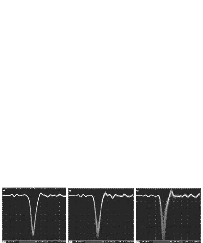
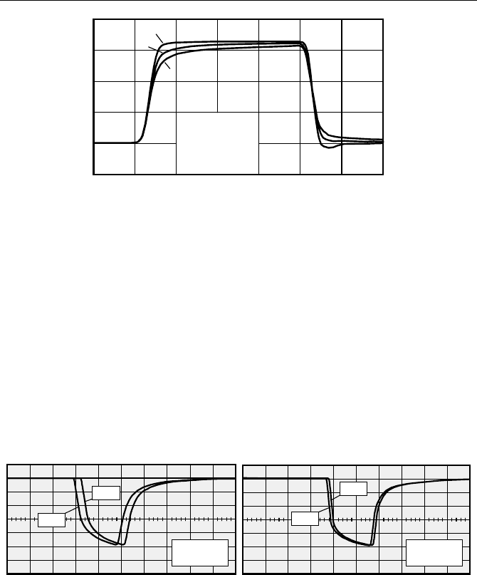
pected due to the limited number of photons within the PMT response. Figure 7.44
shows the output pulses of an H5773
1 photosensor module for light pulses of
200 ps FWHM. The gain control voltage was 0.45 V, 0.6 V, and 0.77 V, corre-
sponding to a gain of about 10
4
, 810
4
, and 610
5
. The light intensity was adjusted
to obtain an average pulse amplitude of 100 mV at 50
:.
Fig. 7.44 Output signal of an H5773 photosensor module used for reference signal genera-
tion. 200 ps diode laser pulse, gain control voltage 0.45 V, 0.6 V, and 0.77 V
Another problem can arise from the small permissible average output current of
the PMT. The absolute limit is normally 100 µA. To obtain good long-term stabil-
ity 10 µA should not be exceeded. For 2 ns pulse width and 100 mV pulse ampli-
tude this current is reached for 2.5 MHz repetition rate. A PMT therefore cannot
be used for synchronisation at high pulse repetition rates.
Ti:Sapphire lasers often deliver a reference signal generated by an internal pho-
todiode. In general the signals can be used as a timing reference for TCSPC. The
signal should be checked for pulse width, rise time, amplitude and polarity. For
TCSPC it is essential that the pulses are free of noise; they must also have less than
7.5 System Connections 307
1 ns rise time and a pulse width of less than 2 or 3 ns. Their amplitude should be
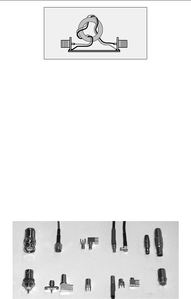
100 mV or more. If the polarity is wrong the pulses can be inverted by transformer
made of two twisted wires wound through a small ferrite ring core, see Fig. 7.45.
The trick in this transformer is that the upper bandwidth limit is determined by
the bandwidth of the transmission line formed by the parallel wires, whereas the
lower bandwidth limit is determined by the inductance formed by the wires on the
core. The characteristic impedance of the parallel wires should be close to
50 Ohm. In practice it may vary between 30 and 80 Ohm due to different wire and
insulation diameter. This impedance mismatch is tolerable if the overall wire
length is less than 3 cm.
7.5 System Connections
7.5.1 Connector Systems
In advanced TCSPC systems external wiring is reduced to a minimum. Neverthe-
less finding the right cables, connectors and adapters can be a nightmare. The
most common connections systems currently used are BNC, SMA, SMB, MCX,
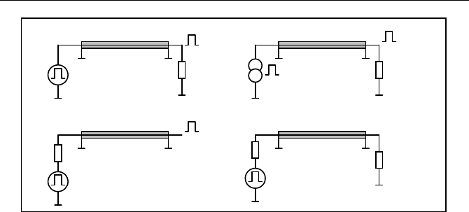
and LEMO connectors. The connectors are shown in Fig. 7.46.
Fig. 7.46 Connection systems. Left to right: BNC, SMA, SMB, MCX, LEMO
SMA ConnectorSMA Connector
Ferrit Core
5 to 10 mm Diameter
GND Plane
Fig. 7.45 Inverting transformer for synchronisation pulses

308 7 Practice of TCSPC Experiments
BNC connectors are inexpensive, reliable, rugged, and relatively easy to as-
semble. However, their performance noticeably degrades at frequencies above
1 GHz. They are relatively large and therefore not very useful for small detectors,
amplifier modules, or PC plug-in cards. Nevertheless, BNC is still the most wide-
spread connector system. BNC is available for cables of different diameter, in-
cluding the commonly used RG56 and RG174 cables. A large number of adapters
to other systems is available, as is a large selection of attenuators for BNC up to
about 1 GHz bandwidth.
SMA connectors are commonly used in systems where BNC connectors are too
large or have insufficient high frequency performance. The connectors are avail-
able in different versions for maximum frequencies from 3 GHz to 20 GHz and for
cables of different diameter, including the commonly used RG56 and RG174
cables. Many adapters between SMA and BNC are available so that mixing both
systems does not cause problems. Attenuators and power splitters are available for
up to 20 GHz bandwidth.
Both BNC and SMA connectors give reliable connections. If they are used to
connect PMTs to preamplifiers, routers or TCSPC inputs, there is negligible dan-
ger of damaging the electronics by cable discharges (see Fig. 7.58, page 316).
SMB and MCX connectors yield reasonably good high-frequency performance
up to about 3 GHz. Connectors are available for the commonly used RG174 cables
and other cables of about 3 mm diameter. However, the selection of attenuators
and adapters for other systems is very limited. They are often used for internal
cable connections between different modules inside of complex electronic devices
or between circuit blocks on the same board. The drawback of MCX and, in a
smaller degree SMB, is that mechanical stress on the cables can result in contact
problems. If SMB or MCX connectors are used to connect a PMT signal, precau-
tions against cable discharge must be taken. SMB and MCX connectors often use
a crimp technique to affix the outer shield of the cable. If the right crimping tool is
not available, it is possible to use the four-jaw chuck of a lathe.
LEMO connectors come in different versions with different pin numbers. Coax-
ial versions for 50
: systems are available. Assembling the connectors is somewhat
tricky. Nevertheless, LEMO connectors are commonly used on NIM modules.
7.5.2 Cables
A cable has a characteristic impedance defined by
'/' CLZ (7.8)
with
L’ and C’ = inductance and capacitance per length unit. An ideal cable does
not introduce signal distortion if it is terminated (or „matched“) with its character-
istic impedance, i.e. connected to a source or a load of the impedance
Z. All that
happens in an impedance-matched cable is that the signal is delayed. The virtual
input impedance of a cable matched with its Z at the output is Z, and vice versa.
The typical termination techniques are shown in Fig. 7.47.
7.5 System Connections 309
Z Z
Z
Z Z
Vin
Vout = Vin
Vin
Vout = Vin
Iin
Vout = Z Iin
Cable
Cable Cable
Cable
c) Input matching
a) Output matching
d) Input and output
matching
Vout = 0.5 Vin
Voltage Source
b) Output matching
Current source
Vin
Fig. 7.47 Cable termination schemes
If the cable is driven by a voltage source and matched with its characteristic
impedance, Z, the output voltage is the same as the input voltage (Fig. 7.47 a). If
the cable is driven by a current source the output voltage is
Z
.
I
in
, i.e. the same as
if the source was connected directly to the load (Fig. 7.47 b). If the cable is driven
by a source of the impedance Z and the output is left open, the output voltage is
the same as the source voltage (Fig. 7.47 c). A cable matched with its Z at both
ends delivers 50% of the source voltage to the load (Fig. 7.47 d). Matching a cable
at both ends can be a reasonable solution if an accurate matching with a purely
resistive
Z cannot be done, e.g. at the input and output of amplifiers.
If a cable is terminated with an impedance different from Z, a part of the signal
is reflected at the load and travels back to the source. If the source is also mis-
matched, the signal is reflected again and appears at the output after twice the
cable transit time. Depending on the relation of the pulse width to the cable length,
and the source and load impedance (which may be not purely resistive), the result-
ing pulse shapes can be very different.
Cables are available for
Z = 50, 60, 75 and 100 :. For measurement equipment
and other wide-band systems only
Z = 50 : is used. The CFD inputs of TCSPC
modules, amplifiers, or routers have internal matching resistors of 50
:. However,
the input impedance of amplifiers or of the pulse shaping network used in CFDs is
often far from being ideally resistive. Moreover, PMTs and photodiodes are cur-
rent sources. Matching at the detector side is avoided because it would decrease
the signal amplitude. The resulting reflections at the input cables of a TCSPC
device can normally be tolerated, especially if some precaution is taken in adjust-
ing the CFD thresholds.
The transit time for the commonly used 50
: cables (RG58, 4.9 mm diameter
and RG174, 2.9 mm diameter) is about 5 ns per meter.
In practice the resistance of the inner and outer conductor and the dielectric loss
of the insulator cause some loss at high frequency. The corresponding distortion of
a pulse edge for the commonly used RG58 (4.9 mm thick) and RG174 (2.9 mm
thick) cables is shown in Fig. 7.48.
310 7 Practice of TCSPC Experiments
500 ps/div
a
b
c
a: Original Pulse
b: 2.5 m RG58 Cable
c: 2.5 m RG174 Cable
Fig. 7.48 Pulse edge distortion of a 2 ns pulse after propagation through 2.5 m RG 56 and
RG 174 cable. The cable was terminated with 50 :
After a steep rise the amplitude increases very slowly and reaches its final
height after a relatively long time. Figure 7.48 shows that for 2.5 m RG56 and
RG 174 cable the loss of rise time and amplitude is still tolerable. The discrimina-
tor chips in CFDs are slower than the cable response so that the timing perform-
ance is not noticeably impaired. However, cables are subject to ageing, and the
loss increases after some years. Therefore, for cables longer than 2.5 m, a low-loss
cable should be used, for instance a RG316 with PTFE dielectric.
Reversed start-stop systems require a stop pulse at the end of the recorded time
interval. It is therefore often necessary to delay the reference pulses from the laser.
The best way to delay the signal is to use a cable, since this does not introduce a
noticeable jitter. It is, however, not commonly known that the transit time in a
cable depends on the temperature. Figure 7.49 shows the delay change in 8 m of a
standard RG 174 cable and RG 316 high-quality cable.
8 m RG174
1 ns / div
23°C
53°C
23°C
8 m RG316
1 ns / div
53°C
Fig. 7.49 Delay change for 8 m of cable for a 30°C increase in temperature. Left: RG174,
Right: RG316, high quality PTFE cable. Total cable transit time is 40 ns.
For 8 m length, or 40 ns delay, the temperature drift is 5 ps/°C for the RG 316
and 13 ps/°C for the RG174. Temperature drift is a strong argument for using
high-quality cables for connections longer than a few meters.
7.5.3 Attenuators and Power Splitters
If the amplitude of a signal is to be reduced for whatever reason, impedance
matching forbids the use of a simple series resistor. Instead, it is necessary to use a
7.5 System Connections 311
resistive network that has an impedance of 50
: at either side if the other side is
terminated with 50
:, see Fig. 7.50, left.
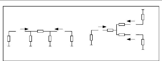
If a signal has to be distributed into several loads, e.g. to trigger two TCSPC
modules from the same laser, a resistive network must be used as well. A 1:2
„power splitter“ is shown in Fig. 7.50, right.
A wide range of attenuators is available for the commonly used SMA and BNC
connector systems. Power splitters are available for splitting a signal into 2, 3 or 4
outputs. The signal amplitude at the outputs is 1/2, 1/3 and 1/4 of the input ampli-
tude, respectively. Unused outputs of a power splitter must be terminated by 50
:
resistors. Attenuators and power splitters of satisfactory bandwidth can be made by
soldering small 0805-size surface-mount resistors directly between the pins of
SMA connectors.
7.5.4 Shielding and Grounding
Improper shielding and grounding of system components is the most frequent
reason for poor time resolution, poor efficiency and poor differential linearity in
TCSPC systems.
RF noise pickup from radio and television transmitters in the detector and ref-
erence lines reduces the signal-to-noise ratio of the signals. The result is poor
timing accuracy, i.e. broadening of the IRF of the TCSPC system. Moreover,
noise can make it impossible to use a sufficiently low CFD threshold to record all
single-photon pulses within the pulse distribution of the detector. The result is a
loss in counting efficiency.
RF pickup from the excitation source or crosstalk between the detector and the
reference lines causes systematic timing errors. The result is a modulation of the
effective CFD threshold and the effective CFD zero cross point. Modulation of the
threshold modulates the detection efficiency. Modulation of the zero cross point
warps the time axis. In either case the result is a ripple in the recorded curves.
Improper grounding can even transform the line frequency into the input sig-
nals. Because the line frequency is usually not synchronous with the signal repeti-
tion rate, the apparent effect for long acquisition times is the same as for RF
pickup. The difference shows up if sequences of curves faster than the line fre-
ZZ
Z Z
R1
R2 R2
Z
Z
Z
Z
Z
Z
R
R
R
R = 16.6 Ohm
for Z = 50 Ohm
Attenuator
1 : 2 Power Splitter
R1 = 2 R2 Z / ( R2 - Z )
222
Fig. 7.50 Reflection-free attenuator (left) and reflection-free power splitter (right)
312 7 Practice of TCSPC Experiments
quency are recorded. The size and the temporal position of the curves are then
modulated according to the line frequency.
Like all high-speed electronics, TCSPC uses impedance-matched cables for the
signal connections. These connections are relatively immune from capacitive
noise pickup. Therefore, inductive coupling is the dominating effect that intro-
duces noise into the system.
The most important cause of inductive noise coupling is ground loops, which
are formed if there are several ground connections between different parts of the
system. If RF radiation from external noise sources penetrates the setup, currents
are induced in the loops. Power supply currents with RF noise components can
also flow in the ground system. The currents flow partially through the outer con-
ductors of the coaxial lines connecting different system components. A part of the
RF noise is transformed into the inner conductors, and thus introduced into the
signal lines. If ground loops are the cause of noise pickup, simple screening of the
system has little effect; the ground loops must be found and disrupted or at least
minimised. Some examples are shown in the figures below.
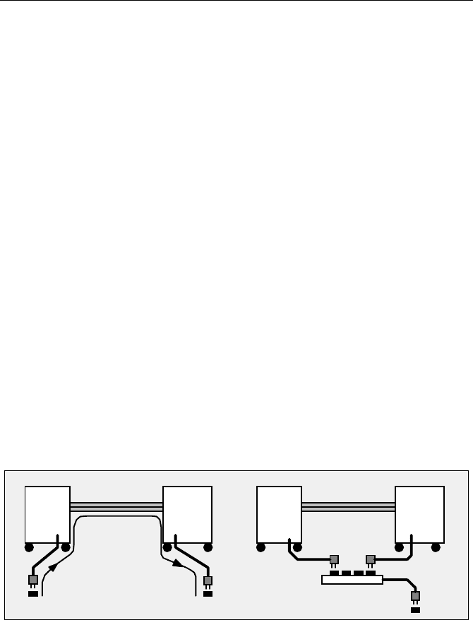
Figure 7.51 shows what can happen if different system components are con-
nected to different power sockets. The power supply system in a large building
forms a huge antenna. In addition, switching transients from power supplies inject
large RF currents into the power lines and the ground connectors. If the sockets of
the system components are connected to different power circuits of the building,
huge compensation currents can flow through the ground conductors and, conse-
quently, through the signal cables that connect the components. Of course, most of
the current flows through the outer shield of the cables. However, the impedance
of the shield is not zero, and some of the current flows through the signal line and
the 50
: matching resistors as well. A simple solution is to supply all system
components from only one power socket, as shown in Fig. 7.51, right.
Detector
TCSPC
Signal Cable
Detector TCSPC
One Socket
Computer ComputerHV Power
Supply
HV Power
Supply
Signal Cable
Socket 1
Socket 2
Current
through
GND line
Fig. 7.51 Ground loop formed by connecting system components to different power sockets
A similar situation can result when a network cable is connected to the computer of
the TCSPC system. Network cables often go through a large part of a building and
form a huge ground loop. Although the cable has no DC connection into the com-
puters, there is enough capacitive coupling to allow RF currents to flow; a network
cable can therefore inject an appreciable noise current into a TCSPC system.
RF currents can also be induced in ground systems by an RF field that pene-
trates the area between the ground plane and the signal cable, see Fig. 7.52, left.
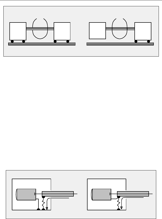
7.5 System Connections 313
The RF field induces a current flowing through the shield of the signal cables. A
part of this current may be introduced into the detector signal. One remedy is to
disrupt the ground loop by isolating the detector (Fig. 7.52, right).
If there is no closed loop there is also less RF current flowing through the cable
and less noise pickup. However, the detector housing may still be enough of an
antenna to send some RF current through the signal cable. Isolating it from the
ground can make the noise pickup even worse, and in fact it may not be possible
to isolate the detector from the system ground because there is an additional con-
nection to a high voltage power supply. If it is not possible to disrupt all ground
loops, the noise pickup can often be reduced by reducing the area enclosed by the
ground loop, i.e. by keeping the cables close to the ground plane. Some additional
improvement may possibly be achieved by putting ferrite ring cores on the cables.
Ferrite cores that can be snapped on the cables are available for this purpose.
In practice it is impossible to completely avoid RF currents flowing through the
signal cables. Therefore, the best viable strategy is to prevent RF noise from being
introduced into the signals. Two wrong design principles are shown in Fig. 7.53.
Signal Cable
AB
Housing
Detector
Signal Cable
Housing
Detector
Noise Current
Noise Current
B
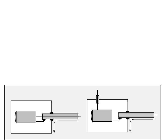
Fig. 7.53 Two examples of improper shielding: The noise voltage induced across the induc-
tance of the ground connection B appears directly in the signal (left) or between the housing
and the signal line (right)
In Fig. 7.53, left, the noise current flowing through the cable shield into the de-
tector housing shares the ground line B with the signal current. The noise current
generates a noise voltage across the inductance of the connection B, and this voltage
appears in the signal. Moreover, the same noise voltage appears between the hous-
Ground Plane
Magnetic component
Detector
Ground Plane
isolated
TCSPC
Signal
Cable
Signal
Cable
TCSPC
Computer
Computer
Detector
HV Power
Supply
of RF Field
Magnetic component
of RF Field
Fig. 7.52 Ground loop, left; avoiding it by isolating one system component from the
ground, right
314 7 Practice of TCSPC Experiments
ing and the detector. Therefore the housing has a poor screening effect. In Fig. 7.53,
right, the noise current and the signal do not share the line B, but there is still an RF
voltage across the inductance of the line B; the housing is not screening adequately.
The correct design is shown in Fig. 7.54. The cable shield is connected to the
housing
directly at the point where it is fed through. The noise current is diverted
directly into the housing. There is neither a noise current in a signal ground line
nor any noise-induced voltage inside the housing. The best way to connect the
cable shield is to build an appropriate coaxial connector into the housing.
Often additional control or power supply lines have to be fed into the housing. The
best way to avoid noise injection via these lines is with a feed-through capacitor or
a feed-through filter, see Fig. 7.54, right. If a feed-through capacitor cannot be
used, i.e. because of the high voltage of a PMT, a coaxial cable should be used and
connected as described for the signal cable.
Signal Cable
Housing
Detector
Noise Current
Signal Cable
Housing
Detector
Noise Current
Vcc
Feedthrough
Capacitor of Filter
Fig. 7.54 Correctly designed RF shielding. The noise current flowing through the cable
shield is diverted outside the housing
It is often hard to believe that there is an appreciable difference between the de-
signs shown in Fig. 7.53 and Fig. 7.54, especially if the length of connection B is
„only a few centimetres“. However, it is precisely wire B that makes the differ-
ence between an ineffective shielding and an effective one, even if the length is
only one or two centimetres. The wrong design shown in Fig. 7.53 can be found in
many variations, including designs with an inductor in the place of the wire B or
housings with no connection to the signal ground at all. All these designs have in
common that the cable shield is not connected to the housing at the point where
the cable is fed through. In practice it can be difficult to correct such designs. For
a signal cable, one possible solution is to scratch the outer insulation open and
solder the cable shield to the housing. For a high-voltage cable such treatment
cannot be seriously considered. An emergency repair that yields at least some
improvement is to wrap a copper foil around the last 10 to 20 cm of the cable and
solder this foil to the housing, see Fig. 7.55. The copper foil forms a capacitor
with the outer connector of the cable, which diverts a large part of the RF noise
current.