Awrejcewicz J. Numerical Simulations of Physical and Engineering Processes
Подождите немного. Документ загружается.


Dynamics of Optical Pulses Propagating in Fibers with Variable Dispersion 7
Under assumption T
1
T
2
eq. (19) can be reduced to eq.(15). Calculation of Q (τ) for the
given A
(z, τ) at the fixed plane z canbedonebyfinite-differenceschemefor(19).Suchscheme
can be somewhat convenient than inverse Fourier transform (18).
2.2 Numerical methods
For modelling of the pulse propagation in single mode fiber split-step Fourier method was
applied (Agraval, 2001), (Malomed, 2006). Figure 1 shows numerical scheme applied for
single propagation step Δz.FunctionsQ
(τ) and ∂P
NL
/∂τ are calculated under a periodic
boundary condition that imposed upon discrete Fourier transform. Use of periodic boundary
condition for the given temporal frame allows to simulate the propagation of pulse train
generated by a modelocked laser. For picosecond pulses which central frequency ω
0
is far
from zero of the group velocity dispersion two dispersion terms β
2
and β
3
are sufficient.
For z-dependent dispersion and nonlinearity coefficients β
m
(z), γ(z) and γ
R
(z) should be
evaluated for each z. The scheme (fig. 1) is performed repeatedly until fiber end is reached.
'
&
$
%
Input A(z, τ)
-
'
&
$
%
Calculate Q(τ) (19) using
2nd-order Adams-Moulton
method
-
'
&
$
%
Calculate
∂P
NL
∂τ
, eq. (11)
?
'
&
$
%
Nonlinearity:
A
NL
(τ)=A(τ) e
−αΔz/2
×
exp
i(γ
R
Q(τ)+γ|A|
2
)Δz
−2ω
−1
0
(∂P
NL
/∂τ)Δz
'
&
$
%
Dispersion:
A
Ω
= F[A
NL
(τ)] ×
exp
i(
β
2
2
Ω
2
+
β
3
6
Ω
3
)Δz
'
&
$
%
Output
A
(z + Δz, τ)
= F
−1
[A
Ω
]
Fig. 1. Numerical scheme for the pulse propagation from plane z to the plane z + Δz. F is the
fast forward Fourier transform (FFT),
F
−1
is the fast inverse Fourier transform (IFT).
2.3 Optical solitons
Optical solitons arize due to interplay between anomalous dispersion (β
2
< 0) and Kerr
self-phase modulation. The solitons are solutions of nonlinear Schrödinger equation (NLS)
∂A
∂z
+ i
β
2
2
∂
2
A
∂τ
2
= iγ|A|
2
A(z, τ). (20)
Eq. (20) obtained from (10) neglecting by high-order dispersion terms (β
m
= 0, m = 3, 4, 5 . . . ),
by stimulated Raman scattering
(γ
R
= 0) and by self-steepening (∂P
NL
/∂τ = 0).
NLS (20) has specific pulselike solutions that either do not change along fiber length or follow
a periodic evolution pattern – such solutions are known as optical solitons. Their properties
283
Dynamics of Optical Pulses Propagating in Fibers with Variable Dispersion

8 Will-be-set-by-IN-TECH
were understood completely using inverse scattering method (Ablowitz et al., 1981). Details
of the inverse scattering method in application to the optical solitons are available in literature
(Agraval, 2001; Akhmanov et al., 1991; Malomed, 2006).
Initial field
A
(0, τ)=N
|β
2
|
γτ
0
sech
τ
τ
0
(21)
where τ
0
is initial pulse width. For integer N (21) give so-called N-soliton solution,
The first-order soliton
(N = 1) corresponds to fundamental soliton It is referred to as
the fundamental soliton because its shape does not change on propagation in the fiber
with fixed dispersion. In the fiber with variable dispersion nonautonomous optical solitons
propagate with varying amplitudes, speeds, and spectra. Analytical solution for fundamental
nonautonomous solitons in (Serkin et al., 2007) is given.
Higher-order solitons are also described by the general solution of Eq. (20)
A
(z, τ)=
N
∑
j=1
A
j
sech
u
j
2
τ
−zv
j
exp
i
φ
0
+
v
j
2
τ
+
u
2
j
−v
2
j
4
z
, (22)
where A
j
= 2τ
0
(|β
2
|/γ)
1/2
Im(λ
j
), v
j
= 2τ
−1
0
Re(λ
j
), u
j
= 2τ
−1
0
Im(λ
j
), λ
j
are roots of
scattering matrix element of a
(λ)=0. Parameters λ
j
give solitonic spectrum. The scattering
matrix is
M
(λ)=
a
(λ) −b
∗
(λ)
b(λ) a
∗
(λ)
=
lim
τ→∞
exp
i
λ
2
τ 0
0
−τ
exp
⎧
⎨
⎩
i
τ
−τ
γ
|β
2
|
0 A
∗
A 0
⎫
⎬
⎭
exp
i
λ
2
τ 0
0
−τ
(23)
Numerical procedure for calculating (23) is described in (Akhmanov et al., 1991). The
scattering matrix is calculated as product
M
(λ)=
∏
l=1,K
M
j
(λ)=
∏
l=1,K
a
l
(λ) −b
∗
l
(λ)
b
l
(λ) a
∗
l
(λ)
(24)
where M
l
(λ) is partial scattering matrix, associated with temporal step Δτ = T/K.Thelocal
time τ
l
= −T/2 + lΔτ, l = 1,...,K, K is the total number of time points,
a
l
(λ)=e
−iλΔτ
cos
(d
l
Δτ)+iλ
sin
(d
l
Δτ)
d
l
(25)
b
l
(λ)=ie
iλΔτ
A
∗
(τ
l
)
γ
|β
2
|
sin(d
l
Δτ)
d
l
, (26)
where d
l
=(λ
2
+ |A(τ
l
)|
2
γ|β
2
|
−1
)
1/2
.
This procedure can be applied to numerical solution of (20) or (10). It allows to separate out
amplitudes and phases of solitons.
284
Numerical Simulations of Physical and Engineering Processes
Dynamics of Optical Pulses Propagating in Fibers with Variable Dispersion 9
Physically, parameters A
j
and v
j
in (22) represent amplitude and frequency shift respectively.
Parameter u
j
determines width of soliton. For the pulse (21)
λ
j
= i(j −1/2), j = 1, N (27)
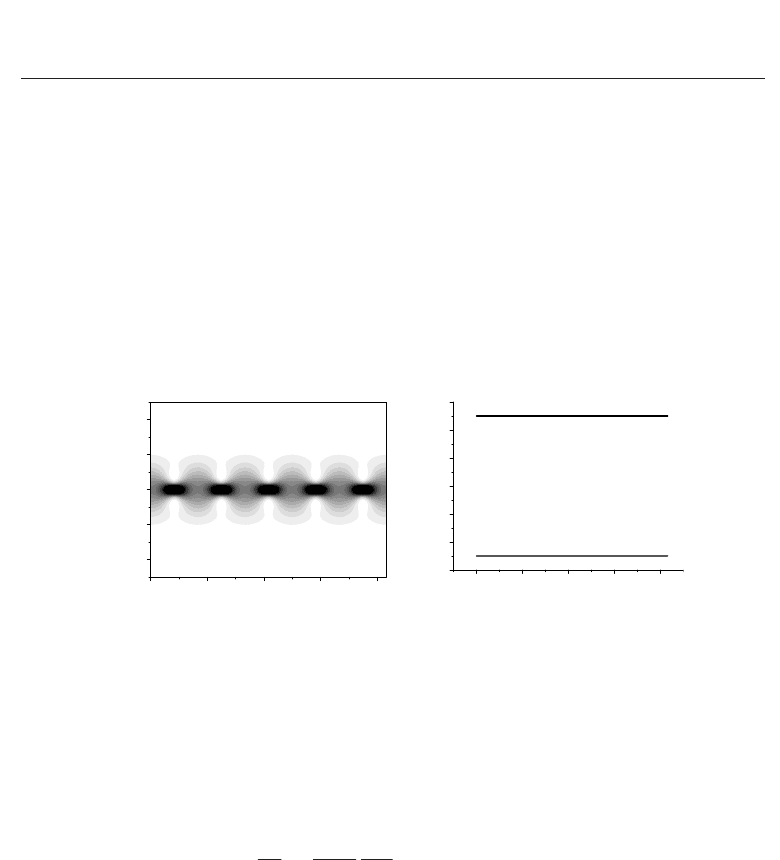
Higher-order solitons
(N > 1) show periodical evolution during propagation. Pulse shape is
repeated over each section of length z
0
(fig.2 a).
z
0
= πτ
2
0
|2β
2
|
−1
(28)
Figure 2 shows dynamics of second-order soliton. Note that soliton parameters Im
(λ) and
Re
(λ) remain unchanged (fig.2 b).
(a) (b)
0.0 0.2 0.4 0.6 0.8
-4
-2
0
2
4
z, km
τ, ps
0.0 0.2 0.4 0.6 0.8
0.4
0.6
0.8
1.0
1.2
1.4
1.6
Im
(λ )
z, km
Fig. 2. Temporal evolution over five soliton periods for the second-order soliton. (a) Pulse
dynamics. Black color corresponds to high intensity. (b) Soliton parameters Im
(λ). N = 2,
β
2
= −12.76 ps
2
/km, γ = 8.2 W km
−1
, z
0
= 0.166 km.
2.4 Soliton fission due to harmonic modulation of the local dispersion
In this section we consider soliton dynamics governed by nonlinear Schrödinger equation
with variable second-order dispersion coefficient
∂A
∂z
+ i
β
2
(z)
2
∂
2
A
∂τ
2
= iγ|A|
2
A(z, τ). (29)
where
β
2
(z)=β
2
(
1 + 0.2 sin(2π z/z
m
+ ϕ
m
)
)
, (30)
In the case of the harmonic periodic modulation of the local GVD coefficient, one may expect
resonances between intrinsic vibrations of the free soliton. When the period of modulation of
the fiber dispersion approaches the soliton period z
0
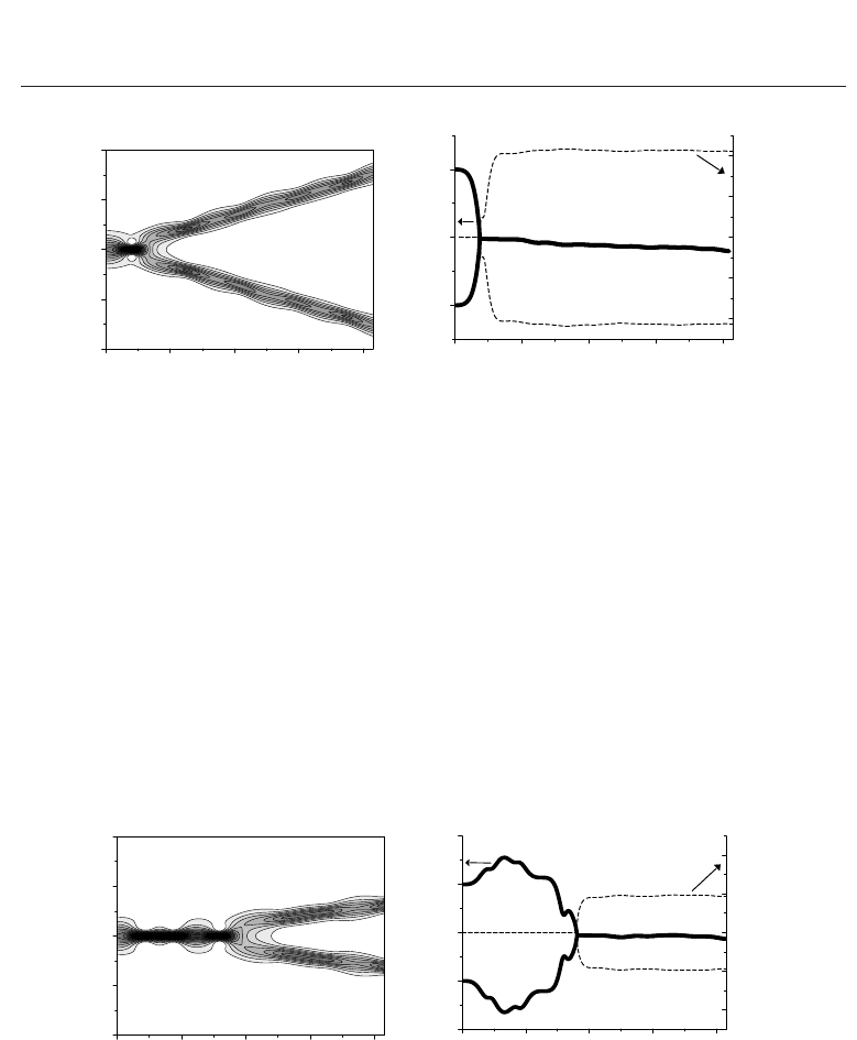
, the soliton splits into pulses propagating
with different group velocities (fig. 3a).
At z
= 0 amplitudes of fundamental solitons are different Im(λ
1
)=0.5, Im(λ
2
)=1.5.
But the group velocity associated with frequency shift is the same Re
(λ
1
)=Re(λ
2
)=0
(fig.3b). After single modulation period z
= z
0
solitons acquire the same amplitudes
Im
(λ
1
)=Im(λ
2
)=0.987, but different group velocities Re(λ
1
)=0.411, Re(λ
2
)=−0.411.
As the pulses propagates along the fiber imaginary part of λ decreases. After five modulation
285
Dynamics of Optical Pulses Propagating in Fibers with Variable Dispersion
10 Will-be-set-by-IN-TECH
(a) (b)
0.0 0.2 0.4 0.6 0.8
-10
-5
0
5
10
z, km
τ
, ps
0.0 0.2 0.4 0.6 0.8
0.5
1.0
1.5
-0.4
-0.2
0.0
0.2
0.4
Im(
λ
)
z, km
Re(
λ
)
Fig. 3. A typical example of the splitting of a second-order soliton N = 2intotwo
fundamental solitons in the NLS equation with the sinusoidal modulation of the local
dispersion coefficient (30). (a) Pulse dynamics; (b) Im
(λ) (solid curve, left axis) and Im(λ)
(dashed curve, right axis) β
2
= −12.76 ps
2
/km, ϕ
m
= π other parameters are the same as
in Fig. 2.
periods
(z = 0.83 km) Im(λ
1
)=Im(λ
1
)=0.89. Decrease of Im(λ(z)) connected with
emerging of dispersive wave under harmonic modulation of the group-velocity-dispersion
coefficient β
2
(z).
Regime shown in fig.3 corresponds to the fundamental resonance between small vibrations of
the perturbed soliton and the periodic modulation of the local GVD. Change of modulation
period z
m
or modulation phase ϕ
m
can degrade the soliton split (Malomed, 2006). In the
fig.4 the pulse performs a few number of irregular oscillations, but finally decay into two
fundamental solitons with opposite group velocities. For ϕ
m
= 0 (fig.4b) group velocity of
output pulses is less by half than the same for ϕ
m
= π (fig.3b).
(a) (b)
0.0 0.2 0.4 0.6 0.8
-10
-5
0
5
10
z, km
τ
, ps
0.0 0.2 0.4 0.6 0.8
0.0
0.5
1.0
1.5
2.0
-0.4
-0.2
0.0
0.2
0.4
Im(
λ
)
z, km
Re(
λ
)
Fig. 4. Splitting of a second-order soliton into two fundamental solitons. (a) Pulse dynamics;
(b) Im
(λ) (solid curve, left axis) and Im(λ) (dashed curve, right axis) β
2
= −12.76 ps
2
/km,
z
m
= z
0
= 0.166 km, ϕ
m
= 0 other parameters are the same as in Fig. 2.
For ϕ
m
= π/4 and N = 2 the width of input pulse performs a large number of irregular
oscillations without splitting into fundamental solitons in spite of resonant conditions z
m
=
z
0
= 0.166 km.
286
Numerical Simulations of Physical and Engineering Processes
Dynamics of Optical Pulses Propagating in Fibers with Variable Dispersion 11
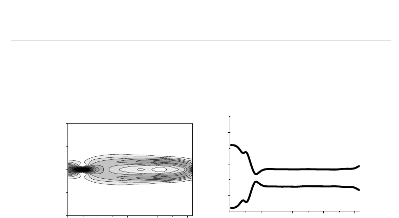
The parameter N = 1.8 corresponds to input pulse (z = 0) which consists of two fundamental
solitons (22) having λ
1
= i0.3 and λ
2
= i1.3. The solitons remains propagating with the
same group velocity (fig.5). For the constant GVD parameter β
2
(z)=β
2
the input pulse
(N = 1.8) performs four periods of oscillations at the propagation distance (z = 0.83 km).
(a) (b)
0.0 0.2 0.4 0.6 0.8
-10
-5
0
5
10
z, km
τ
, ps
0.0 0.2 0.4 0.6 0.8
0.5
1.0
1.5
Im(λ)
z, km
Fig. 5. Propagation of the pulse with N = 1.8. other parameters are the same as in Fig. 2.
During propagation Re
(λ
1
(z)) = Re(λ
2
(z)) = 0
3. Fission of optical solitons in dispersion oscillating fibers
Dispersion oscillating fibers have a periodic or quasi-periodic variation of the core diameter
(Sysoliatin et al., 2008). Fission of second-order solitons or high-order solitons occurs due to
longitudinal oscillation of the fiber dispersion and nonlinearity. In this section the results
of numerical simulations of soliton fission in dispersion oscillating fiber are presented.
Comparative analysis of experimental results and results of modified nonlinear Schrödinger
equation based model is given. Effect of stimulated Raman scattering on the soliton fission is
discussed.
3.1 Experimental confirmation
The solitons splitting described by the nonlinear Schrödinger equation with periodic
perturbation was analysed in (Hasegava et al., 1991) published in 1991. However, the lack of
a suitable fibers delayed experimental observation. Soliton splitting in dispersion-oscillating
fiber was first observed in an experiment (Sysoliatin et al., 2008) that used a mode-locked laser
(PriTel UOC) capable of emitting picosecond optical pulses near 1.55 μm , a wavelength near
which optical fibers exhibit anomalous GVD together with minimum losses. Pulse repetition
rate was 10 GHz. The pulses were amplified by erbium-doped fiber amplifier (EDFA) up to
W
=350 mW average power. The time bandwidth product for amplified pulses is found to
be about T
FWHM
Δν = 0.304, where T
FWHM
= 1.76τ
0
is a pulse duration and Δν is the FWHM
spectral pulse width. After EDFA, the pulses were launched into the DOF through fusion
splicing with a single mode fiber. After propagation in 0.8-km length of DOF pulses were
analyzed by intensity autocorrelator “Femtochrome” with the large scan range exceeding 100
ps and “Ando AQ6317” optical spectrum analyzer with a resolution bandwidth of 0.02 nm
(fig.6).
287
Dynamics of Optical Pulses Propagating in Fibers with Variable Dispersion

12 Will-be-set-by-IN-TECH
DOF
EDFA
AC
OSA
OSCI
Pritel
UOC
10 GHz
Fig. 6. Experimental setup: Pritel UOC, picosecond pulse source; EDFA, Er-doped fiber
amplifier; DOF, dispersion oscillating fiber; AC, autocorrelator; OSA, optical spectrum
analyzer, OSCI, wide-bandwidth oscilloscope.
The DOF was drawn in Fiber Optics Research Center (Moscow, Russia) from the preform with
W-profile of refractive index. The manufactured DOF has linear loss 0.69 dB/km at 1550 nm.
The fiber diameter varied slightly during the drawing in accordance with prearranged law.
The variation of outer diameter of the fiber along its length is described by the sine-wave
function
d
(z)=d
0
(1 + d
m
sin(2πz/z
m
+ ϕ
m
)), (31)
where d
0
= 133 μm, d
m
= 0.03 is the modulation depth, z
m
= 0.16 km is the modulation
period, ϕ
m
is the modulation phase. For 0.8-km length of DOF in these experiments, ϕ
m
= 0
at one fiber end and ϕ
m
= π at other fiber end, according to eq.(31). Thus, the modulation
phase will be different for pulses launched into opposite fiber-ends.
With the average power of input pulse train below 120 mW the pulses transmitted through
DOF were not split. The autocorrelation trace of output pulses have a shape typical for a
train of single pulses separated by 100 ps interval. When average input power was increased,
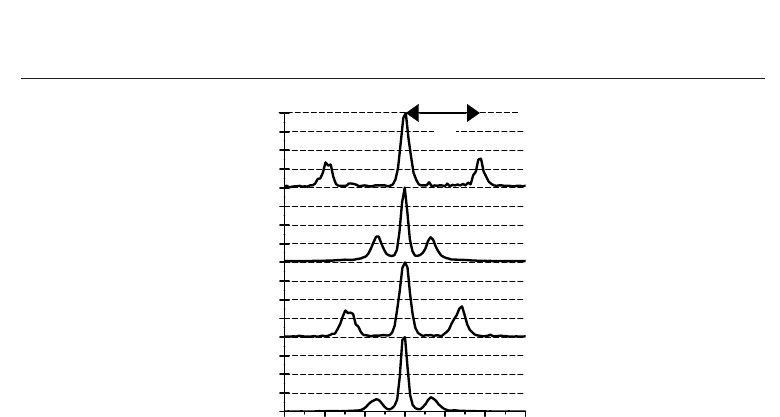
the autocorrelation trace of output pulses demonstrated three peaks (see Fig.7). Normalized
intensity autocorrelation is given by:
C
(τ)=
|E(t)|
2
|E(t −τ)|
2
dt
|E(t)|
4
dt
−1
, (32)
where E
(t) is electric field, t is the time, τ is autocorrelation delay time. Autocorrelations
shown in Fig.7 correspond to two pulses E
(t)=A
1
(t − T/2)+A
2
(t + T/2) separated by
temporal interval T.ThevalueofT can be found measuring the distance between central and
lateral peaks of autocorrelation function as it was shown in Fig.7(a).
The pulse splitting arises due to the fission of second order soliton. In the fiber
with longitudinal variation of dispersion the second-order soliton decays into two pulses
propagating with different group velocities. One of the pulses has red carrier frequency
shift while the other has blue shift with respect to the initial pulse carrier frequency. The
temporal separation between pulses depends on the difference between group velocities
which are determined by pulse frequency shifts. In Fig.7 the pulse splitting dependence on
the modulation phase and input pulse width is demonstrated. For ϕ
m
= π (Fig.7(a)(c)) the
temporal interval T between pulse peaks is higher than the same for ϕ
m
= 0 (Fig.7(b)(d)).
Accordingly the largest frequency shift corresponds to the case shown in Fig.7(a)(c).
At time delay τ
= ±T the intensity autocorrelation (32) is given by
C
(±T)=I
12
/(1 + I
2
12
), (33)
288
Numerical Simulations of Physical and Engineering Processes
Dynamics of Optical Pulses Propagating in Fibers with Variable Dispersion 13
-30 -20 -10 0 10 20 30
T
(a)
(b)
(c)
(d)
Normalized signal
τ
, ps
Fig. 7. Intensity autocorrelation traces of output pulses after propagation 0.8-km DOF. (a)
The input average power is P
= 147.3 mW. The input pulse width is T
FWHM
= 1.75 ps.
Modulation phase is ϕ
m
= π.(b)P = 150.5 mW, T
FWHM
= 1.75 ps, ϕ
m
= 0. (c) P = 167.4 mW,
T
FWHM
= 2.05 ps, ϕ
m
= π.(d)P = 167.4 mW, T
FWHM
= 2.05 ps, ϕ
m
= 0. The temporal interval
between the peaks of output pulses T is given by the distance between peaks of
autocorrelation trace as it shown in Fig.7(a).
where I
12
= |A
1
(0)|
2
/|A
2
(0)|
2
if |A
1
(0)|
2
< |A
2
(0)|
2
and I
12
= |A
2
(0)|
2
/|A
1
(0)|
2
if
|A
1
(0)|
2
> |A
2
(0)|
2
, |A
1
(0)|
2
and |A
2
(0)|
2
are peak intensities of output pulses. When the
input pulse splits symmetrically
(I
12
= 1) the autocorrelation become C(±T)=0.5. For
autocorrelation trace shown in Fig.7(a) C
(T)=0.38, C(T)=0.33 (Fig.7(b)), C(T)=0.41
(Fig.7(c)), C
(T)=0.19 (Fig.7(d)). The value of C(T) is underestimated due to the insufficient
sensitivity of second harmonic generation (SHG) autocorrelator. However, it can be seen that
for the same input power the value of C
(T) is higher for ϕ
m
= π (Fig.7(a)(c)) in comparison
with the case ϕ
m
= 0 (Fig.7(b)(d)). That means the case ϕ
m
= π is preferable for generation of
pulse pairs with nearly identical peak intensity
(|A
1
(0)|
2
|A
2
(0)|
2
).
The splitting of second-order solitons produces two fundamental solitons (Bauer et al., 1995;
Hasegava et al., 1991). The soliton spectrum is not broadened due to self-phase modulation
because the last is balanced by negative dispersion. Spectral broadening shown in Fig.8 arises
mainly due to the opposite frequency shifts of two pulses.
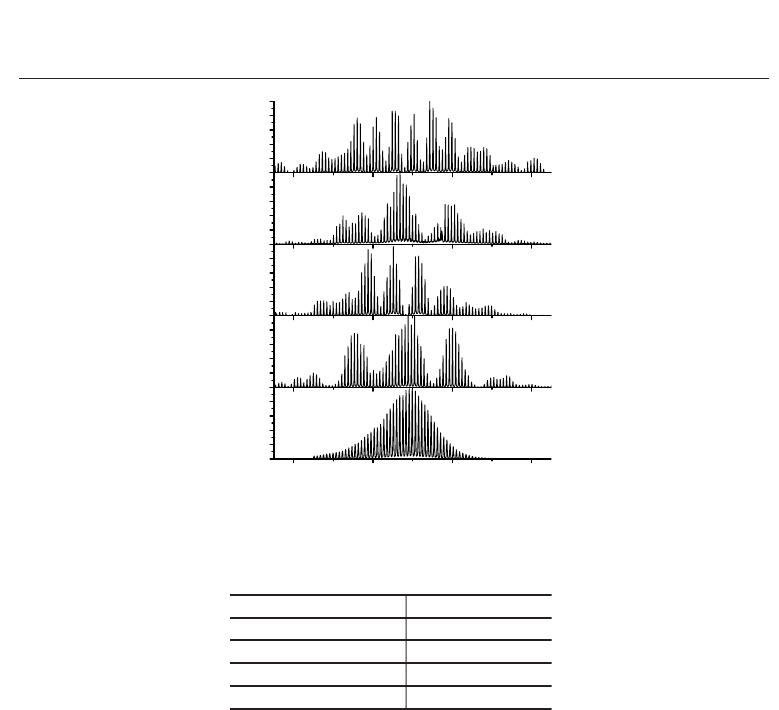
In time domain, the pulses are well separated (Fig.7), while in frequency domain the spectra
are overlapped. Interference between these spectra leads to the modulation of the envelope of
output spectrum (Fig.8(a)(b)). To a first approximation, the intensity of output spectrum can
be expressed as follows:
F
(ω)=|A
1
(ω)e
−iω(t−T/2)
+ A
2
(ω)e
iω(t+T/2)
|
2
= |A
1
|
2
+ |A
2
|
2
+ 2|A
1
||A
2
|cos[ωT −φ
1
(ω)+φ
2
(ω)], (34)
where F
(ω) is the spectral intensity at DOF output, A
1,2
are the spectra of the first and second
pulse, φ
1,2
= arg(A
1,2
) are spectral phases. Eq. 34 shows that output spectrum is modulated
289
Dynamics of Optical Pulses Propagating in Fibers with Variable Dispersion
14 Will-be-set-by-IN-TECH
1548 1550 1552 1554
(b)
(e)
(c)
Wavelength (nm)
(a)
Normalized spectral intensity
(d)
Fig. 8. Pulse train spectra. (a),(b),(c),(d) are the spectra of the output pulses, which
autocorrelation traces are shown in Fig.7(a),(b),(c),(d) correspondingly. (e) the spectrum of
input pulse train; FWHM spectral width of input pulses is 1.38 nm (0.172 THz).
T estimated by eq. 34 T measured
17. ps (from Fig.8(a)) 18.3 ps (Fig.7(a))
6.3 ps (from Fig.8(b)) 6.6 ps (Fig.7(b))
13. ps (from Fig.8(c)) 14. ps (Fig.7(c))
6.3 ps (from Fig.8(d)) 6.8 ps (Fig.7(d))
Table 1. Temporal interval between the peaks of output pulses.
by cosine function which period depends on the temporal interval T between two pulses. In
the Table 1 the temporal interval between peaks of output pulses T is listed. The first column
contains values of T estimated from spectra (Fig.8) by means of eq.(34). The second column
contains the values directly measured from autocorrelation traces (Fig.7). In eq.(34) functions
φ
1,2
(ω) are not known and assumed to be constant. This leads to underestimation of the value
of T obtained from spectrum.
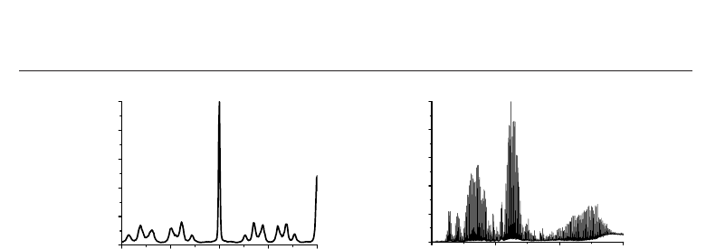
At large average power of input pulses train the autocorrelation trace (Fig.9(a)) and spectrum
(Fig.9(b)) become more complicated. Initial pulse splits into a few low-intensity pulses and
one high-intensity pulse which carrier frequency has a large red shift due to Raman scattering
(Dianov et al., 1985). In Fig.9(b) the spectrum of Raman shifted pulse is located in wavelength
range between 1554 nm and 1559 nm.
3.2 Modelling of soliton propagation in dispersion oscillating fibers
This section deals with solitons in the practically important model of the fibers with
periodically modulated dispersion. Numerical model includes z-dependent second order
and third-order dispersion coefficients β
2
(z), β
3
(z), stimulated Raman scattering and pulse
self-steepening (eq. 10).
290
Numerical Simulations of Physical and Engineering Processes
Dynamics of Optical Pulses Propagating in Fibers with Variable Dispersion 15
-100 -50 0 50 100
0.0
0.2
0.4
0.6
0.8
1.0
Normalized signal
τ
, ps
1545 1550 1555 1560
0.0
0.2
0.4
0.6
0.8
1.0
Spectral intensity (arb.un.)
Wavelength (nm)
(a) (b)
Fig. 9. High power pulse transmission through DOF. (a) Autocorrelation trace. (b) pulse train
spectrum. Width of initial pulse is T
FWHM
= 2.05 ps, The input average power is
P
= 258.9 mW. The phase of modulation is ϕ = 0.
For manufactured DOF which diameter is given by (31) the longitudinal variation of
dispersion coefficients β
2
and β
3
can be expressed with the following approximation
β
2
(z)=β
2
[
1 + β
2m
sin(2π z/z
m
+ ϕ
m
)
]
, (35)
β
3
(z)=β
3
[
1 + β
3m
sin(2π z/z
m
+ ϕ
m
)
]
, (36)
where
β
2
= −12.76 ps
2
km
−1
, β
3
= 0.0761 ps
3
km
−1
, β
2m
= 0.2, β
3m
= 0.095. The
dispersion coefficients (35,36) were evaluated from the measurements of the dispersion of
three fibers with the fixed outer diameter: 128 μm, 133 μm and 138 μm. All of three fibers and
DOF are manufactured from the same preform.
Nonlinear medium polarization includes the Kerr effect and delayed Raman response
P
NL
(z, t)=γ(z)|A|
2
A + γ
R
(z)QA(z, t),whereγ(z) and γ
R
(z) are nonlinear coefficients:
γ
(z)=γ
[
1 −γ
m
sin(2π z/z
m
+ ϕ
m
)
]
, (37)
γ
R
(z)=γ
R
[
1 −γ
m
sin(2π z/z
m
+ ϕ
m
)
]
, (38)
γ = 8.2 W
−1
km
−1
and γ
R
= 1.8 W
−1
km
−1
, γ
m
= 0.028. These coefficients are obtained
by calculating of effective area of fundamental mode.
The equation (10) was solved using standard split-step Fourier algorithm (see section 2.2).
Simulations were carried out with hyperbolic secant input pulses. In simulations, we
characterize the input pulses by the soliton number (order) N. The number of pulses that
arise due to the splitting of high-order soliton is determined primarily by N (Bauer et al.,
1995; Hasegava et al., 1991; Malomed, 2006).
The pulse splitting is most efficient in resonant regime when the modulation period z
m
is
equal to the soliton period z
0
= 0.16π|β
2
|
−1
T
2
FWHM
(Hasegava et al., 1991; Tai et al., 1988).
For initial pulse width T
FWHM
= 2.05 ps (Fig.10) the soliton period z
0
= 0.166 km is close to
the modulation period z
m
= 0.160 km. For ϕ
m
= π only one modulation period of DOF is
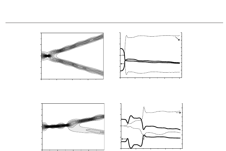
necessary for the soliton fission (Fig.10(a)). After propagation of 0.8 km of DOF the temporal
separation between resulting pulses become T
= 14 ps. The same value was obtained in
experiment (Fig.7(c)). For ϕ
m
= 0 the soliton fission arises after propagation of 0.6 km in DOF
291
Dynamics of Optical Pulses Propagating in Fibers with Variable Dispersion
16 Will-be-set-by-IN-TECH
0.0 0.2 0.4 0.6
-10
-5
0
5
10
z, km
τ
, ps
0.0 0.2 0.4 0.6 0.8
0.0
0.5
1.0
1.5
2.0
-0.6
-0.4
-0.2
0.0
0.2
0.4
0.6
Im(
λ
)
z, km
Re(
λ
)
(a)
0.0 0.2 0.4 0.6
-10
-5
0
5
10
z, km
τ
, ps
0.0 0.2 0.4 0.6 0.8
0.0
0.5
1.0
1.5
2.0
-0.4
-0.2
0.0
0.2
0.4
Im(
λ
)
z, km
Re(
λ
)
(b)
Fig. 10. Numerical simulation of the pulse evolution in DOF. Width of initial pulse is
T
FWHM
= 2.05 ps, The pulse has soliton order N = 1.8. (a) ϕ = π.(b)ϕ = 0.
(Fig.10(b)). The temporal separation between output pulses is T
= 6.2psthatisagreewell
with experiment (Fig.7(d)).
For the initial pulse width T
FWHM
= 1.75 ps the soliton period is z
0
= 0.126 km. This value does
not obey the resonant condition z
0
= z
m
. However for input pulse width T
FWHM
= 1.75 ps the
temporal separation between pulses (Fig.7(a)) is higher than the same for resonant conditions
(T
FWHM
= 2.05 ps, z
0
= 0.166 km z
m
) (Fig.7(c)). Experimental observation is in agreement
with calculations. Numerical simulations show that such effect arises due to the simultaneous
action of the periodical modulation of the fiber dispersion and stimulated Raman scattering.
The frequency red shift due to the Raman scattering is inversely proportional to the fourth
power of the pulse width (Tai et al., 1988). As result the change of the pulse group velocity
and correspondent temporal separation between pulses will be higher for the shorter pulse
width
(T
FWHM
= 1.75 ps).
The input soliton decays into pulses with different peak intensities (Fig.10). Such asymmetry
arises due to stimulated Raman scattering. For ϕ
m
= π (Fig.10(a)) the ratio of the peak of
low-intensity pulse to the peak of high-intensity pulse is I
12
= 0.9. For ϕ
m
= 0 (Fig.10(b))
we obtain I
12
= 0.21. Numerical calculations confirm our conclusions (Section 3.1) that the
case ϕ
m
= π is preferable for the symmetrical splitting of input pulse. Note that without
stimulated Raman scattering and third-order dispersion term the pulse with N
= 1.8 does not
split (see fig. 5).
The pulses become propagating with different group velocities (Fig.10) due to the shift of
the carrier frequency. For the modulation phase ϕ
m
= π instantaneous frequency shift
292
Numerical Simulations of Physical and Engineering Processes
