Awrejcewicz J. Numerical Simulations of Physical and Engineering Processes
Подождите немного. Документ загружается.

Numerical Simulations of the Long-Haul RZ-DPSK Optical Fibre Transmission System
583
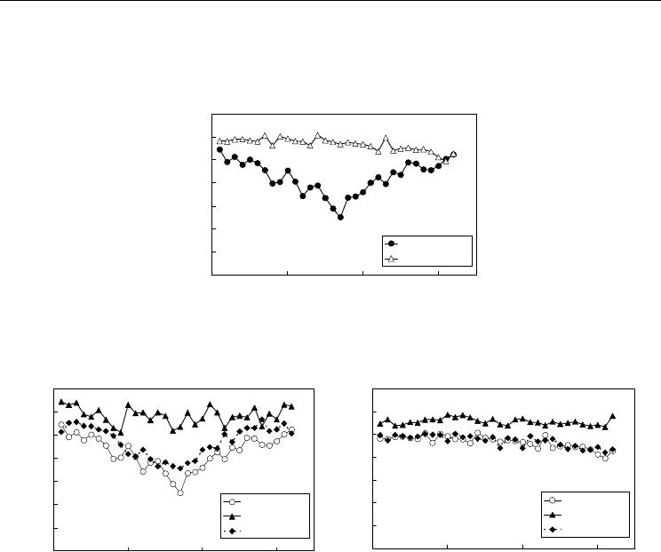
without the SPM for the block type map and the block-less type map were 13.8 and 14.6 dB,
respectively. The averaged Q-factors without the XPM for the block type map and the block-
less type map were 12.9 and 13.7 dB, respectively
8
9
10
11
12
13
14
15
0102030
Channel number
Q-factor (dB)
Block type
Block-less typ
e
Fig. 5. Simulated transmission performance of the block type and block-less type map
8
9
10
11
12
13
14
15
0 102030
Channel number
Q-factor (dB)
All effects
Without SPM
Without XPM
9
10
11
12
13
14
15
16
0102030
Channel number
Q-factor (dB)
All effects
Without SPM
Without XPM
(A) Block type (B) Block-less type
Fig. 6. Impact of the SPM and XPM for the block type and block-less type map
Two conclusions can be drawn from these results. The first conclusion is the SPM causes the
wavelength-dependent degradation for the block type map, and the degradation is
significant in the region close to the system zero dispersion wavelength. The second
conclusion is the XPM plays a relatively minor role of the performance degradation of the
block type map while it has virtually no effect for the block-less type map. It can be
concluded that the block-less type dispersion map reduces the impairments of both the SPM
and the XPM for the long-haul RZ-DPSK transmission compared to the block type
dispersion map, and improves the system performance.
4. Impact of number of dispersion blocks
Comparing the block type map and the block-less type map, one notable difference between
them is number of zero-crossing points of the cumulative dispersion along the transmission
distance. This is due to number of dispersion blocks in the system. Therefore, in this section,
the effect of number of dispersion blocks upon the transmission performance of the long-
Numerical Simulations of Physical and Engineering Processes
584
haul RZ-DPSK system is studied. At first, the system performance of the block type
dispersion map was evaluated as a function of the transmission distance. Then, the system
performances of several different block type dispersion maps were evaluated as a function
of number of dispersion blocks in the system.
4.1 Simulated dispersion maps
The model used for this study was the same as the previous study, and it is shown in Fig. 3.
The simulated block type dispersion maps were using NZDSF1, NZDSF2, and SMF shown
in Table 1. The output power and the noise figure of the optical amplifier repeater were set
to +11 dBm and 4.5 dB, respectively. The repeater span length was 100km, and the total
transmission distance was 6300 km.
Number of dispersion blocks was adjusted by changing the position of the SMF span in the
transmission line. Then, different style of the dispersion maps was realized whereas the
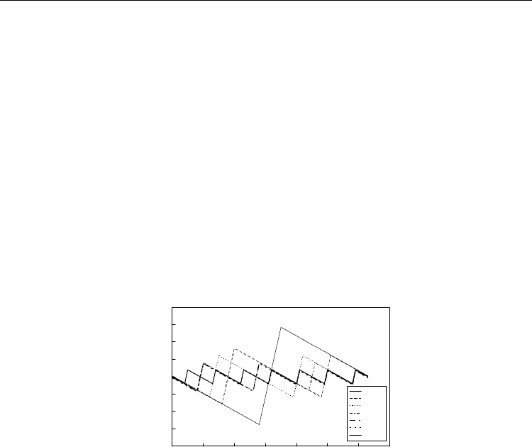
fibre parameters were kept identical. Fig. 7 shows these maps. Number of dispersion blocks
was one to seven corresponding to the number of dispersion map. This means Map 1 has
one dispersion block, Map 2 has two dispersion blocks, and so on.
-8000
-6000
-4000
-2000
0
2000
4000
6000
8000
0 1000 2000 3000 4000 5000 6000 7000
Transmission distance (km)
Cumulative dispersion (ps/nm)
MAP 1
MAP 2
MAP 3
MAP 4
MAP 5
MAP 6
MAP7
Fig. 7. Dispersion maps with different number of dispersion blocks
4.2 Transmission distance dependency
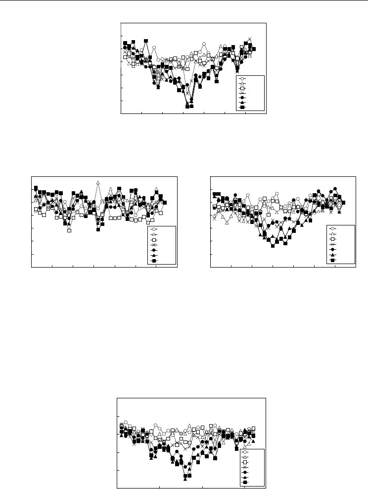
At first, the system performance of Map 7 was evaluated as a function of the transmission
distance. Fig. 8 shows the results. The horizontal axes shows the channel number, and the
vertical axes shows the relative Q-factor for each transmission distance. The relative Q-factor
is defined as the difference from the value of channel 32. As seen in this figure, the
performance dip near the system zero dispersion wavelength became obvious when the
transmission distance was increased. This tendency implies that large number of dispersion
blocks causes the performance degradation near the system zero dispersion wavelength.
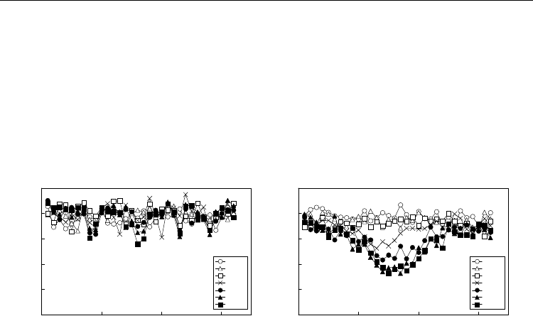
Then, the effects of the SPM and the XPM were investigated. Fig. 9 (A) and (B) show the
transmission distance dependency without the SPM and the XPM, respectively. As shown in
Fig. 9 (A), there is not any significant dip when the SPM effect was ignored, while the
degradation near the centre channels was obvious for Fig. 9 (B). These results imply that
large number of dispersion blocks combined with the SPM degrades the performance of the
RZ-DPSK signal near the system zero dispersion wavelength.
Numerical Simulations of the Long-Haul RZ-DPSK Optical Fibre Transmission System
585
-2.5
-2
-1.5
-1
-0.5
0
0.5
1
0 5 10 15 20 25 30 35
Channel Number
Relative Q-factor (dB)
900km
1800km
2700km
3600km
4500km
5400km
6300km
Fig. 8. Relative channel performance as a function of the transmission distance
-2.5
-2
-1.5
-1
-0.5
0
0.5
1
0 5 10 15 20 25 30 35
Channel Number
Relative Q-factor (dB)
900km
1800km
2700km
3600km
4500km
5400km
6300km
-2.5
-2
-1.5
-1
-0.5
0
0.5
1
0 5 10 15 20 25 30 35
Channel Number
Relative Q-factor (dB)
900km
1800km
2700km
3600km
4500km
5400km
6300km
(A) without the SPM (B) without the XPM
Fig. 9. Relative channel performance as a function of the transmission distance without the
SPM and the XPM
4.3 Number of dispersion blocks dependency
Next, the system performance of several different block type dispersion maps shown in Fig.
7 was evaluated. Fig. 10 shows the results. As seen in the figure, the performance dip near
10
11
12
13
14
15
0 102030
Channel Number
Q-factor (dB)
MAP 1
MAP 2
MAP 3
MAP 4
MAP 5
MAP 6
MAP 7
Fig. 10. Transmission performance of different number of dispersion blocks
Numerical Simulations of Physical and Engineering Processes
586
the centre channels became significant when number of dispersion blocks was increased.
This tendency clearly shows that large number of dispersion blocks causes the performance
degradation near the system zero dispersion wavelength. Then, the effects of the SPM and
the XPM were investigated. Fig. 11 (A) and (B) show the dispersion map dependency
without the SPM and the XPM, respectively. As shown in Fig. 11 (A), there is not any
significant dip when the SPM effect was ignored, while the degradation near the centre
channels was obvious for Fig. 11 (B). These results show that large number of dispersion
blocks combined with the SPM degrades the performance of the RZ-DPSK signal near the
system zero dispersion wavelength.
10
11
12
13
14
15
0 102030
Channel Number
Q-factor (dB)
MAP 1
MAP 2
MAP 3
MAP 4
MAP 5
MAP 6
MAP 7
10
11
12
13
14
15
0 102030
Channel Number
Q-factor (dB)
MAP 1
MAP 2
MAP 3
MAP 4
MAP 5
MAP 6
MAP 7
(A) without the SPM (B) without the XPM
Fig. 11. Transmission performance of different number of dispersion blocks without the
SPM and the XPM
5. Comparison of dispersion flattened fibre and non-zero dispersion
shifted fibre
The DFF is a well-known solution to improve the performance of the long-haul IM-DD
system, but there are not enough studies to characterize the transmission performance
difference between the DFF and the NZDSF for the RZ-DPSK based system. In this section, a
comparative study of the long-haul RZ-DPSK system performance using the DFF and the
NZDSF is conducted.
5.1 Simulation model
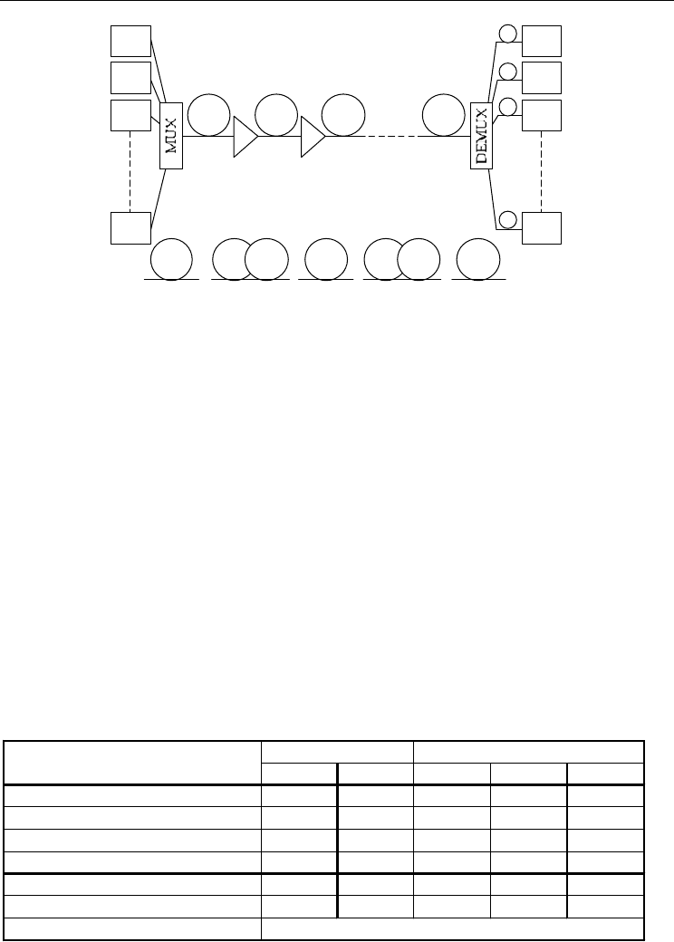
Fig. 12 shows a schematic diagram of the simulation model. Ninety-six optical TXs were
employed, and the signal wavelengths were ranged from 1540.5 nm to 1559.5 nm with 0.2
nm channel separation. The bit rate and the pattern were 10 Gbit/s and 2
9
De Brujin
sequence, respectively. The PSK signal was assumed to be generated by a MZM, and the
waveform applied for the two arms of the MZM was a raised cosine with the NRZ format.
The RZ waveform was applied after the PSK modulation, and the waveform was also raised
cosine. The pulse duty ratio was 50 %. The MUX did not have any wavelength selective
function, and the modulated pattern of each transmitter was randomized at the output of
the MUX. Three different sets of the initial pattern at the output of the MUX were used for
the simulation to reduce the pattern dependent XPM impact (Essiambre & Winzer, 2005),
and the obtained results were averaged over these three sets.
Numerical Simulations of the Long-Haul RZ-DPSK Optical Fibre Transmission System
587
Optical
ampli fier
TX1
TX2
TX3
TX96
RX1
RX2
RX3
RX96
SMFNZDSF1
()
D
ispersion compensation
(NZDSF system only)
Fibre Fibre Fibre Fibre
Fibre
=
or
N
Z
D
S
F
2
SLASLA
or
I
D
F
or
()
()
()
Optical
amplifier
Fig. 12. A schematic diagram of the simulation model
The optical DEMUX had the second-order Gaussian shape, and the 3dB bandwidth of the
DEMUX was 0.1 nm. As the relative dispersion slope of the SLA and the IDF was the same,
the cumulative dispersion of all signal channels after the transmission was equal to zero for
the DFF system. On the other hand, the cumulative dispersion of each channel was
equalized to be 100 ps/nm for the NZDSF system after the DEMUX.
The transmission line comprised optical amplifier repeaters and fibres. The noise figure of
the optical amplifier repeater was set to 4.5 dB. The ASE noise generated by the amplifier
had a random complex electrical field, and it was added to the complex electrical field of the
optical signal. The amplifier spacing was 100 km. The wavelength dependent gain of the
optical amplifier was ignored in the simulation.
The fibre span comprised the DFF or the NZDSF. The DFF was composed from the super
large area fibre (SLA) and the inverse dispersion fibre (IDF) (OFS), and there were two types
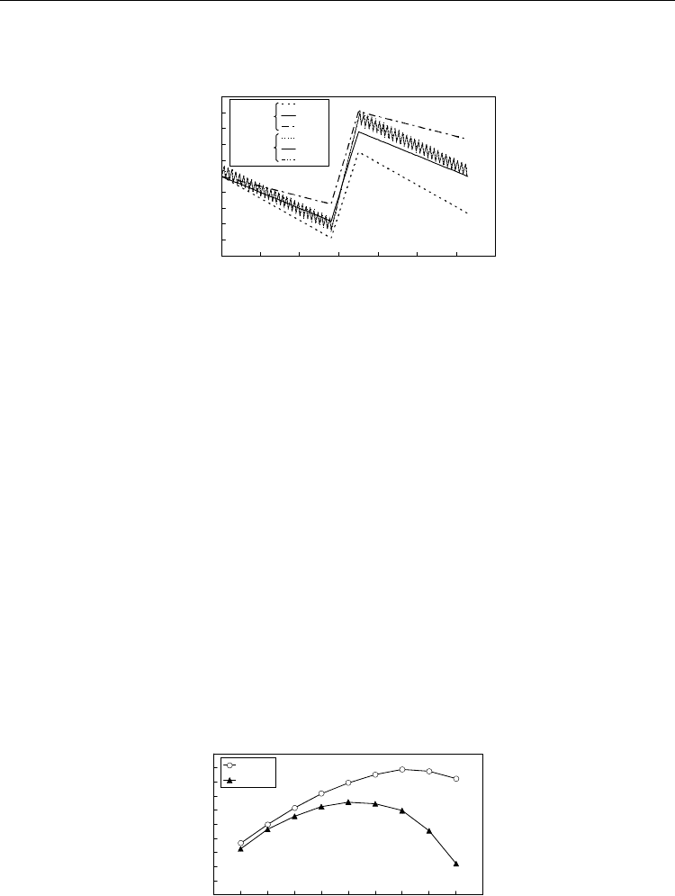
of the NZDSF. The parameters of the fibres are summarized in Table 2. The DFF span loss
was 21.1 dB and the NZDSF span loss was 21.0 dB. Fig. 13 shows the dispersion map of the
DFF system and the NZDSF system. The block-less type map was employed. Three different
wavelengths, 1540.5, 1550, and 1559.5 nm were shown in the figure to show the difference
between the fibres clearly. Both maps had pure positive fibre spans in the centre of the
system, and the span length of this section was 96 km for the DFF system and 100 km for the
NZDSF system. Thus, the total transmission distance was 6272 km and 6300 km for
SLA IDF NZDSF1 NZDSF2 SMF
Length (km) 65 35 50 50 100
Loss (dB/km) 0.190.250.210.210.18
Chromatic dispersion (ps/nm/km) 20.0 -44.0 -2.0 -2.0 16.0
Dis
p
ersion slo
p
e
(p
s
/
nm
2
/
km
)
0.06 -0.132 0.10 0.06 0.06
Effective area
(
m
2
)
106 30 70 50 72
Relative dispersion slope 0.003 0.003 - - -
Nonlinear refractive index
2.6 x 10
-2 0
DFF NZDSF
Table 2. Fibre parameters of the DFF and the NZDSF
Numerical Simulations of Physical and Engineering Processes
588
the DFF system and the NZDSF system, respectively. The positive dispersion fibre used for
the DFF system was the SLA, and that for the NZDSF system was the SMF.
-10000
-8000
-6000
-4000
-2000
0
2000
4000
6000
8000
10000
0 1000 2000 3000 4000 5000 6000 7000
Distance (km)
Cumulative dispersion (ps/nm)
1540.5
1550
1559.5
1540.5
1550.0
1560.5
NZDSF
DFF
Fig. 13. Dispersion maps of the DFF and the NZDSF systems
5.2 Comparison of the dispersion flattened fibre and the non-zero dispersion shifted
fibre based system
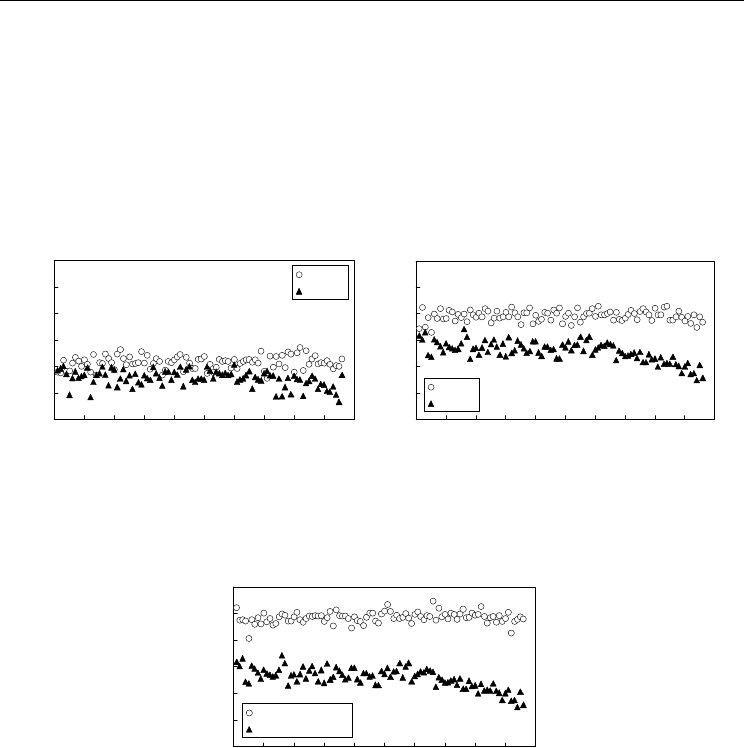
At first, the system performance was evaluated as a function of the repeater output power. Fig.
14 shows the results. The horizontal axis shows the repeater output power, and the vertical
axis shows the averaged Q-factor of ninety-six channels. As seen in the figure, when the
repeater output power was smaller than +14 dBm, the performance of both systems was
similar. This result shows that the difference of the fibre parameters did not have so significant
impact on the transmission performance when the optical fibre nonlinearity was not
dominant. The performance was improved as the repeater output power was increased up to
+18 dBm for the DFF system and up to +16 dBm for the NZDSF system. This result clearly
shows that the DFF had smaller transmission impairment caused by the optical fibre
nonlinearity than the NZDSF. When the repeater output power was +16 dBm, averaged Q-
factors for the DFF system and the NZDSF system were 13.9 dB and 12.6 dB, respectively.
There was 1.3 dB performance difference between the DFF and the NZDSF systems when the
repeater output power was set to the optimum value of the NZDSF system. Furthermore,
when the repeater output power was +18dBm, averaged Q-factor for the DFF system was
improved to 14.9 dB. Therefore, the DFF system had 2.3 dB performance advantage against the
NZDSF system when the system was operated under the optimum condition.
6
7
8
9
10
11
12
13
14
15
16
11 12 13 14 15 16 17 18 19 20 21
Repeater output power (dBm)
Q (dB)
DFF
NZDSF
Fig. 14. Repeater output power dependency of the DFF and the NZDSF system
Numerical Simulations of the Long-Haul RZ-DPSK Optical Fibre Transmission System
589
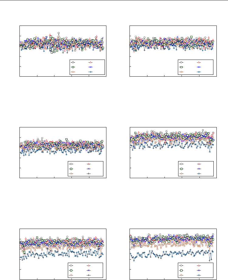
Fig. 15 shows channel dependence of the Q-factor for the DFF system and the NZDSF
system. Fig. 15 (A) shows +14dBm repeater output power, and Fig. 15 (B) shows +16dBm
repeater output power. The DFF system showed slightly improved performance than the
NZDSF system in Fig. 15 (A), and it showed clearly better performance in Fig. 15 (B). In
addition, Fig. 16 shows the comparison at the optimum repeater output power. The DFF
system at +18 dBm repeater output power showed superior performance than the NZDSF
system at +16 dBm. These results show that the DFF is effective to improve the transmission
performance of the long-haul RZ-DPSK system, but the repeater output power should be
high enough to fully utilize the advantage of the DFF.
10
11
12
13
14
15
16
0 102030405060708090100
Channel number
Q (dB)
DFF
NZDSF
10
11
12
13
14
15
16
0 102030405060708090100
Channel number
Q (dB)
DFF
NZDSF
(A) +14 dBm repeater output power (B) +16 dBm repeater output power
Fig. 15. Transmission performance of 96 channels with the DFF and the NZDSF system
10
11
12
13
14
15
16
0 102030405060708090100
Channel number
Q (dB)
DFF (+18dBm)
NZDSF (+16dBm)
Fig. 16. Transmission performance of 96 channels with the optimum repeater output power
As mentioned above, the DFF system exhibited 2.3 dB performance improvement compared
to the NZDSF system when the repeater output power was optimized. The reason of this 2.3
dB advantage could be explained in two steps. Firstly, there is 2 dB difference of the
optimum repeater output power. This difference could be justified
by the effective area difference between the SLA and NZDSF1. As the effective areas of the
SLA and the NZDSF1 are 107 m
2
and 70 m
2
, respectively, the difference of the effective
area in dB scale is 1.8 dB, and this could cause 2 dB difference of the optimum power level.
Roughly speaking, 2 dB improvement of the repeater output power improves the optical
signal to noise ratio of 2 dB, and it can improve the Q-factor of 2 dB. Secondly, remaining
0.3dB discrepancy could be attributed to channel dependent degradation of the NZDSF

Numerical Simulations of Physical and Engineering Processes
590
system at +16 dBm repeater output power. As shown in Fig. 15 (B), channel performance of
the NZDSF system above the system zero dispersion wavelength clearly exhibits gradual
degradation when the channel wavelength becomes longer. Actually, if the average Q-factor
of the NZDSF system is calculated using only fourty-eight shorter wavelength channels (i.e.,
channel 1 to 48), the average is improved to 12.8 dB.
6. Impact of number of dispersion blocks for the dispersion flattened fibre
based system
As discussed in section 4, for the NZDSF based system, the block type dispersion map is not
optimum for the RZ-DPSK format and number of dispersion blocks changes the
transmission performance significantly. This implies that the transmission performance of
the DFF based system is also affected significantly by the number of dispersion blocks.
Therefore, this section focuses on this issue whether the block type dispersion map causes
the performance degradation of the DFF based RZ-DPSK system.
6.1 Simulation model
The simulation model used for this study was similar to that of the previous section, and it
is shown in Fig. 12. The DFF parameters and span configuration was the same, and each
DFF span had negative chromatic dispersion of -240ps/nm. The cumulative negative
dispersion was compensated by the SLA only span. To compose the block type dispersion
map, one dispersion block comprised nine DFF spans and one SLA only span. The SLA only
span was placed at the sixth span. The span length of the SLA only span was 108km. There
were six dispersion blocks, and the total transmission distance was 6048km.
Six different dispersion maps were used for the simulation. Number of dispersion blocks
was changed for each map. Map 1 had one dispersion block, Map 2 had two dispersion
blocks, and so on. Map 1, 2, 3, and 6 had uniform dispersion blocks while Map 4 and 5 had
two different block lengths within the system. Fig. 17 shows the dispersion maps used for
this study. Note that the difference was only the position of SLA only span, and the physical
parameters of the fibres were identical.
6.2 Number of dispersion blocks dependency
Fig. 18 shows the performance of ninety-six channels after 6048km transmission as a
function of the repeater output power. As seen in the figure, for small repeater output
power of below +14 dBm, there was not any significant difference between the maps, but
the performance of map 6 became inferior than the others when the repeater output power
was increased above +16 dBm. These results clearly indicate that the nonlinear penalty of
the system strongly depends on the dispersion map design.
Fig. 19 shows the average Q-factor of ninety-six channels as a function of the repeater output
power and the dispersion map. It is obvious that increasing the number of dispersion blocks
leads to performance degradation in higher repeater output power (i.e., higher nonlinear
regime). Regarding dispersion map design, the tendency is the same as the NZDSF based
system, and it is favourable for the DFF system to reduce number of dispersion blocks to
improve the performance.

Numerical Simulations of the Long-Haul RZ-DPSK Optical Fibre Transmission System
591
-8000
-6000
-4000
-2000
0
2000
4000
6000
8000
0 1000200030004000500060007000
Distance (km)
Cumulative dispersion (ps/nm)
-8000
-6000
-4000
-2000
0
2000
4000
6000
8000
0 1000200030004000500060007000
Distance (km)
Cumulative dispersion (ps/nm)
(A) Map 1 (B) Map 2
-8000
-6000
-4000
-2000
0
2000
4000
6000
8000
0 1000200030004000500060007000
Distance (km)
Cumulative dispersion (ps/nm)
-8000
-6000
-4000
-2000
0
2000
4000
6000
8000
0 1000200030004000500060007000
Distance (km)
Cumulative dispersion (ps/nm)
(C) Map 3 (D) Map 4
-8000
-6000
-4000
-2000
0
2000
4000
6000
8000
0 1000200030004000500060007000
Distance (km)
Cumulative dispersion (ps/nm)
-8000
-6000
-4000
-2000
0
2000
4000
6000
8000
0 1000200030004000500060007000
Distance (km)
Cumulative dispersion (ps/nm)
(E) Map 5 (F) Map 6
Fig. 17. Dispersion maps
Numerical Simulations of Physical and Engineering Processes
592
8
9
10
11
12
13
0 20406080100
Channel number
Q-factor (dB)
Map 1 Map 2
Map 3 Map 4
Map 5 Map 6
9
10
11
12
13
14
0 20406080100
Channel number
Q-factor (dB)
Map 1 Map 2
Map 3 Map 4
Map 5 Map 6
(A) +13 dBm (B) +14 dBm
10
11
12
13
14
15
0 20406080100
Channel number
Q-factor (dB)
Map 1 Map 2
Map 3 Map 4
Map 5 Map 6
10
11
12
13
14
15
0 20406080100
Channel number
Q-factor (dB)
Map 1 Map 2
Map 3 Map 4
Map 5 Map 6
(C) +15 dBm (D) +16 dBm
11
12
13
14
15
16
0 20406080100
Channel number
Q-factor (dB)
Map 1 Map 2
Map 3 Map 4
Map 5 Map 6
11
12
13
14
15
16
0 20406080100
Channel number
Q-factor (dB)
Map 1 Map 2
Map 3 Map 4
Map 5 Map 6
(E) +17 dBm (F) +18 dBm
Fig. 18. Transmission performance of 96 channels as a function of the repeater output power
