ASME Section VIII div 2 2010. ASME Boiler and Pressure Vessel Code. Alternative Rules
Подождите немного. Документ загружается.

2010 SECTION VIII, DIVISION 2
4-345
4.17.8 Figures
B
B
g
o
h
N
r
h
n
g
1
0.25 in. min. radius
T
g
2
A
Hub
(a)
g
1
g
2
A
B
Hub
g
o
h
N
r
h
n
0.25 in. min. radius
T
(b)
g
1
=g
o
H
p
or
H
m
H
T
G
A
H
G
W
e
C
h
T
h
D
H
D
B
N
h
n
T
(c)
Hub
g
1
=g
o
H
p
or
H
m
H
T
G
A
H
G
W
e
C
h
T
h
D
H
D
B
N
h
n
T
(d)
Hub
A
A
(e)
W/2
Neutral Axis
Cj/2
e
b
L
h
B
c
B [Note (1)]
Clamp
L
a
W/2
C
w
Neutral
Axis
X
r
C
t
l
c
l
m
Section A-A
C
i
(f)
C
g
W
e
C
Clamp
Notes:
1) See Figure 4.17.2 for section B-B
2) Clamp may have spherical depressions at bolt holes to facilitate the use of spherical nuts
Note 2
h
G
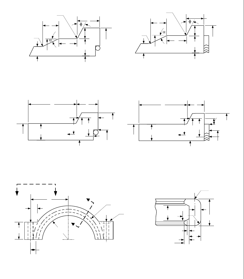
Figure 4.17.1 – Typical Hub and Clamp Configuration
2010 SECTION VIII, DIVISION 2
4-346
L
w
B
c
L
a
L
w
= C
w
(a)
B
c
L
w
L
a
(b)
(c)
C
w
L
w
L
w
= C
w
B
c
L
a
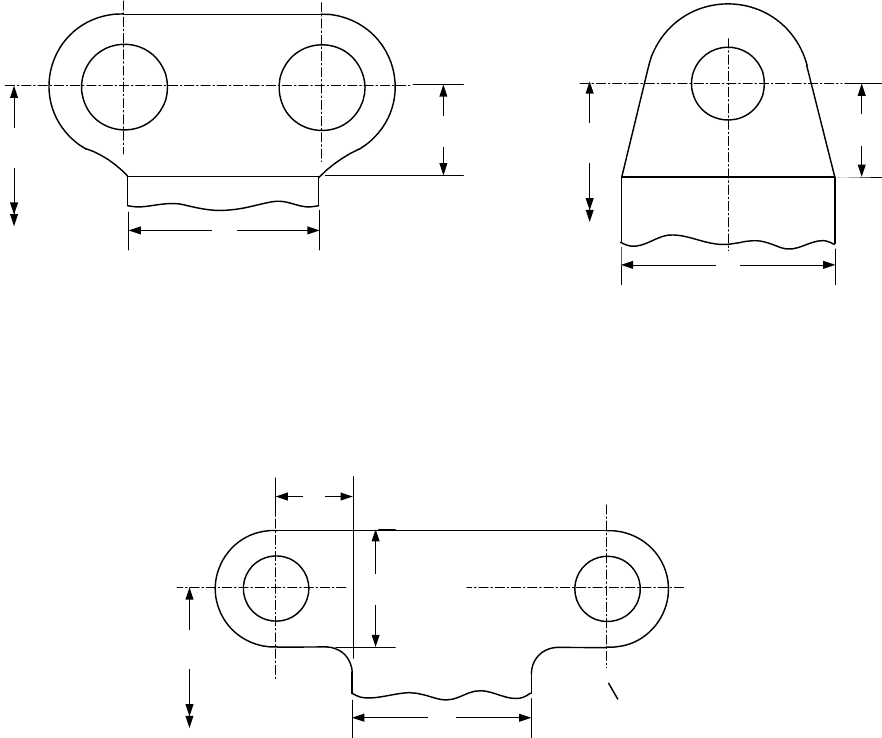
Figure 4.17.2 – Typical Clamp Lugs Configurations
标准分享网 www.bzfxw.com 免费下载
2010 SECTION VIII, DIVISION 2
4-347
4.18 Design Rules for Shell and Tube Heat Exchangers
4.18.1 Scope
The rules in paragraph 4.18 cover the minimum requirements for design, fabrication and inspection of shell-
and-tube heat exchangers.
4.18.2 Terminology
a) U-Tube Heat Exchanger – A heat exchanger with one stationary tubesheet attached to the shell and
channel. The heat exchanger contains a bundle of U-tubes attached to the tubesheet (see Figure
4.18.1.Sketch (a)).
b) Fixed Tubesheet Heat Exchanger – A heat exchanger with two stationary tubesheets, each attached to
the shell and channel. The heat exchanger contains a bundle of straight tubes connecting both
tubesheets (see Figure 4.18.1. Sketch (b)).
c) Floating Tubesheet Heat Exchanger – A heat exchanger with one stationary tubesheet attached to the
shell and channel, and one floating tubesheet that can move axially. The heat exchanger contains a
bundle of straight tubes connecting both tubesheets (see Figure 4.18.1. Sketch (c)).
4.18.3 General Design Considerations
a) The design of all components shall be in accordance with the applicable rules of all Parts of this
Division.
b) The design of a bolted flat cover where the cover bears against a gasket at the pass partition shall
consider the effects of deflection.
c) The design of flanges shall consider the effects of pass partition gasketing in determining the minimum
required bolt loads,
o
W and
g
W , of paragraph 4.16. When the tubesheet is gasketed between the
shell and channel flanges, the shell and channel flange bolt loads are identical and shall be treated as
flange pairs in accordance with paragraph 4.16.
d) Rules for U-tube heat exchangers are covered in paragraph 4.18.7.
e) Rules for fixed tubesheet heat exchangers are covered in paragraph 4.18.8.
f) Rules for floating tubesheet heat exchangers are covered in paragraph 4.18.9.
g) Distribution and vapor belts where the shell is not continuous across the belt shall be designed in
accordance with paragraph 4.18.12.
h) Requirements for tubes shall be as follows.
1) The allowable axial tube stresses in fixed and floating tubesheet heat exchangers shall be in
accordance with paragraphs 4.18.8 and 4.18.9.
2) The thickness of U-tubes after forming shall not be less than the design thickness.
4.18.4 General Conditions of Applicability for Tubesheets
a) The tubesheet shall be flat and circular. It shall be of uniform thickness, except that the flanged
extension may differ in thickness as determined in paragraph 4.18.5. The tubesheet shall be uniformly
perforated over a nominally circular area, in either equilateral triangular or square patterns. However,
untubed lanes for pass partitions are permitted
b) The channel component integral with the tubesheet (Configurations a, e, f and A for U-Tube, Fixed, and
Floating Tubesheets) shall be either a cylinder or a hemispherical head (see Figure 4.18.15). The
hemispherical head rules shall be used when the head is attached directly to the tubesheet and there
are no cylindrical straight sections between the head and the tubesheet.

2010 SECTION VIII, DIVISION 2
4-348
c) The tube side and shell side pressures are assumed to be uniform. These rules do not cover weight
loadings or pressure drop.
d) If these conditions of applicability are not satisfied, the design shall be in accordance with Part 5.
4.18.5 Tubesheet Flanged Extension
4.18.5.1 Scope
The following rules cover the determination of the required thickness of the tubesheet flanged extension when
bolt loads are transmitted to the extended edge of the tubesheet. The required thickness of the extended
portion of the tubesheet may differ from that required for the interior of the tubesheet as calculated in
paragraphs 4.18.7, 4.18.8, and 4.18.9.
4.18.5.2 Conditions of Applicability
The general conditions of applicability given in paragraph 4.18.4 apply.
4.18.5.3 Design Considerations
a) The designer should take appropriate consideration of the stresses resulting from the pressure test
required in paragraph 4.1.6.2 and Part 8. Special consideration shall be required for tubesheets that
are gasketed on both sides when the pressure test in each chamber is conducted independently, and
the bolt loading is only applied to the flanged extension during the pressure test.
b) If the tubesheet is grooved for a peripheral gasket, the thinnest section of the flanged extension shall
not be less than
r
h . Figure 4.18.16 depicts
r
h for some representative configurations
c) The thickness
r
h shall be calculated for both operating and gasket seating conditions, and the greater
of the two values shall be used. For operating conditions, the values of
S at the design temperature
and
o
WW= (see paragraph 4.16) shall be used. For gasket seating, the values of S at atmospheric
temperature and
g
WW= (see paragraph 4.16) shall be used.
4.18.5.4 Calculation Procedure
The procedure for calculating the minimum required thickness of the tubesheet flanged extension
r
h is as
follows:
0.5
1.9
g
r
Wh
h
SG
⎛⎞
=
⎜⎟
⋅
⎝⎠
(4.18.1)
4.18.6 Tubesheet Characteristics
4.18.6.1 Scope
These rules cover the determination of the ligament efficiencies, effective depth of the tube side pass partition
groove, and effective elastic constants to be used in the calculation of U-tube, fixed, and floating tubesheets.
4.18.6.2 Conditions of Applicability
The general conditions of applicability given in paragraph 4.18.4 apply.
标准分享网 www.bzfxw.com 免费下载

2010 SECTION VIII, DIVISION 2
4-349
4.18.6.3 Design Considerations
a) Elastic moduli and allowable stresses shall be taken at the design temperatures. However, for cases
involving thermal loading, it is permitted to use the operating temperatures instead of the design
temperatures.
b) When the values calculated in this section are to be used for fixed tubesheets, they shall be determined
in both the corroded and uncorroded conditions.
c) The tube expansion depth ratio given by Equation (4.18.4) may be either calculated or chosen as a
constant.
4.18.6.4 Calculation
Procedure
a) Determination of Effective Dimensions and Ligament Efficiencies – From the geometry (see Figures
4.18.2 and 4.18.3) and material properties of the exchanger, calculate the required parameters in
accordance with paragraphs 4.18.6.4.a.1 or 4.18.6.4.a.2.
1) For geometries where the tubes extend through the tubesheet (see Figure 4.18.2.Sketch (b)),
calculate the following parameters.
2
oot
Drd=+ (4.18.2)
t
p
d
p
μ
−
=
(4.18.3)
01
tx
l
where
h
ρρ
=≤≤ (4.18.4)
()
*max 2 , 2
tT tT
tt tt
ES
ddt dt
ES
ρ
⎡⎤
⎧⎫
⎛⎞⎛⎞
=− −
⎨⎬
⎢⎥
⎜⎟⎜⎟
⎝⎠⎝⎠
⎩⎭
⎣⎦
(4.18.5)
()
0.5
2
4min , 4
*1
Lo
o
ADp
pp
D
π
−
⎛⎞
⋅
⎡⎤
⎣⎦
=−
⎜⎟
⎜⎟
⎝⎠
(4.18.6)
**
*
*
p
d
p
μ
−
=
(4.18.7)
()
max , 0.0
ggt
'
hhc
⎡⎤
=−
⎣⎦
(4.18.8)
2) For tubes welded to the backside of the tubesheet (see Figure 4.18.2. Sketch (d)), calculate the
following parameters.
2
oo
Drd=+ (4.18.9)
p
d
p
μ
−
=
(4.18.10)
2010 SECTION VIII, DIVISION 2
4-350
()
0.5
0
2
4min , 4
*1
L
o
ADp
pp
D
π
−
⎛⎞
⋅
⎡⎤
⎣⎦
=−
⎜⎟
⎜⎟
⎝⎠
(4.18.11)
*
*
*
p
d
p
μ
−
=
(4.18.12)
()
'
max , 0.0
ggt
hhc
⎡⎤
=−
⎣⎦
(4.18.13)
b) Determination of Effective Elastic Properties – Determine the values for
*
E
E and *
ν
based on *
μ
and
h/p using Table 4.18.1 (equilateral triangular pattern) or Table 4.18.2 (square pattern).
4.18.7 Rules for the Design of U-Tube Tubesheets
4.18.7.1 Scope
These rules cover the design of tubesheets for U-tube heat exchangers. The tubesheet may have one of the
six configurations shown in Figure 4.18.4.
a) Configuration a – tubesheet integral with shell and channel.
b) Configuration b – tubesheet integral with shell and gasketed with channel, extended as a flange.
c) Configuration c – tubesheet integral with shell and gasketed with channel, not extended as a flange.
d) Configuration d – tubesheet gasketed with shell and channel, extended or not extended as a flange.
e) Configuration e – tubesheet gasketed with shell and integral with channel, extended as a flange.
f) Configuration f – tubesheet gasketed with shell and integral with channel, not extended as a flange.
4.18.7.2 Conditions of Applicability
The general conditions of applicability given in paragraph 4.18.4 apply.
4.18.7.3 Design Considerations
a) The various loading conditions to be considered shall include the normal operating conditions, the
startup conditions, the shutdown conditions, and the upset conditions, which may govern the design of
the tubesheet.
1) For each of these conditions, the following loading cases shall be considered:
i) Loading Case 1 – Tube side pressure
t
P acting only
(
)
0
s
P
=
.
ii) Loading Case 2 – Shell side pressure
s
P acting only
(
)
0
t
P
=
.
iii) Loading Case 3 – Tube side pressure
t
P and shell side pressure
s
P acting simultaneously.
2) When vacuum exists, each loading case shall be considered with and without the vacuum.
3) When differential design pressure is specified by the user, the design shall be based only on
Loading Case 3. If the tube side is the higher-pressure side,
t
P shall be the tube side design
pressure and
s
P shall be
t
P less the differential design pressure. If the shell side is the higher-
pressure side,
s
P shall be the shell side design pressure and
t
P shall be
s
P less the differential
标准分享网 www.bzfxw.com 免费下载
2010 SECTION VIII, DIVISION 2
4-351
design pressure.
4) The designer should take appropriate consideration of the stresses resulting from the pressure test
required by paragraph 4.1.6.2 and Part 8.
b) As the calculation procedure is iterative, a value h shall be assumed for the tubesheet thickness to
calculate and check that the maximum stresses in tubesheet, shell, and channel are within the
maximum permissible stress limits.
c) The designer shall consider the effect of deflections in the tubesheet design, especially when the
tubesheet thickness
h
is less than the tube diameter.
d) The designer may consider the tubesheet as simply supported in accordance with paragraph 4.18.7.5
4.18.7.4 Calculation Procedure
a) STEP 1 – Determine
o
D ,
μ
, *
μ
, and
g
'
h
from paragraph 4.18.6.4.a.
b) STEP 2 – Calculate the diameter ratios
s
ρ
and
c
ρ
using the following equations.
,,
s
s
o
D
Configurations a b c
D
ρ
=−
(4.18.14)
,,
s
s
o
G
Configurations d e f
D
ρ
=− (4.18.15)
,,
c
c
o
D
Configurations a e f
D
ρ
=− (4.18.16)
,,
c
c
o
G
Configurations b c d
D
ρ
=− (4.18.17)
For each loading case, calculate moment
TS
M
due to pressures
s
P and
t
P acting on the unperforated
tubesheet rim.
()
()
()
(
)
22 2
11 11
16
os s sc c t
TS
DPP
M
ρρ ρρ
⎡⎤
−+−−+
⎣⎦
=
(4.18.18)
c) STEP 3 – Calculate
hp. Determine *EE and *
ν
using paragraph 4.18.6.4.b. For Configurations
a, b, c, e and f, proceed to STEP 4. For Configuration d, proceed to STEP 5.
d) STEP 4 – Calculate the shell coefficients.
1) Configurations a, b and c:
()
()
0.25
2
0.5
12 1
s
s
sss
Dtt
ν
β
⎡⎤
−
⎣⎦
=
+
⎡⎤
⎣⎦
(4.18.19)

2010 SECTION VIII, DIVISION 2
4-352
()
3
2
61
s
ss
s
s
Et
k
β
ν
=
−
(4.18.20)
22
3
6
1
2
ss s
ss
Dk h
h
h
β
λβ
⎛⎞
=++
⎜⎟
⎝⎠
(4.18.21)
2
1
4 2
s
s
s
ss
D
Et
ν
δ
⎛⎞
=−
⎜⎟
⎝⎠
(4.18.22)
()
s
1
ssss s
kh
ω
ρβδ β
=+
(4.18.23)
2) Configurations a, e and f:
()
()
0.25
2
0.5
12 1
c
c
ccc
Dtt
ν
β
⎡⎤
−
⎣⎦
=
+
⎡⎤
⎣⎦
(4.18.24)
()
3
2
61
ccc
c
c
Et
k
β
ν
=
−
(4.18.25)
22
3
6
1
2
cc c
cc
Dk h
h
h
β
λβ
⎛⎞
=++
⎜⎟
⎝⎠
(4.18.26)
2
1
4 2
cc
c
cc
D
For a Cylinder
Et
ν
δ
⎛⎞
=−
⎜⎟
⎝⎠
(4.18.27)
2
1
4 2
cc
c
cc
D
For a Hemispherical Head
Et
ν
δ
−
⎛⎞
=
⎜⎟
⎝⎠
(4.18.28)
()
1
ccccc c
kh
ω
ρβδ β
=+ (4.18.29)
e) STEP 5 – Calculate the diameter ratio,
K
, and the coefficient
F
.
o
A
K
D
=
(4.18.30)
()( )
1* ln
*
sc
EK
F Configuration a
E
νλλ
−++
=−
(4.18.31)
()( )
1* ln
,
*
s
EK
F Configurations b c
E
νλ
−+
=−
(4.18.32)
标准分享网 www.bzfxw.com 免费下载

2010 SECTION VIII, DIVISION 2
4-353
()( )
1* ln
*
EK
F Configuration d
E
ν
−
=−
(4.18.33)
()( )
1* ln
,
*
c
EK
F Configurations e f
E
νλ
−+
=−
(4.18.34)
f) STEP 6 – For each loading case, calculate the moment
*
M
acting on the unperforated tubesheet rim.
*
TS c t s s
M
M P P Configuration a
ω
ω
=+− − (4.18.35)
()
*
2
cc
TS s s
o
CGW
M
M P Configuration b
D
ω
π
−
=−− −
(4.18.36)
()
1
*
2
cc
TS s s
o
GGW
M
M P Configuration c
D
ω
π
−
=−− −
(4.18.37)
()
max
*
2
cs
TS
o
GGW
M
M Configuration d
D
π
−
=+ −
(4.18.38)
[
]
max
max ,
s
c
WWW= (4.18.39)
()
*
2
ss
TS c t
o
CGW
M
M P Configuration e
D
ω
π
−
=++ −
(4.18.40)
()
1
*
2
ss
TS c t
o
GGW
M
M P Configuration f
D
ω
π
−
=++ −
(4.18.41)
g) STEP 7 – For each loading case, calculate the maximum bending moments acting on the tubesheet at
the periphery,
p
M
, and at the center,
o
M
.
()
2
*
32
1
ost
p
DFP P
M
M
F
−
−
=
+
(4.18.42)
()()
2
3*
64
ost
op
DPP
MM
ν
+−
=+
(4.18.43)
Determine the maximum bending moment
M
acting on the tubesheet.
max ,
op
MMM
⎡⎤
=
⎣⎦
(4.18.44)

2010 SECTION VIII, DIVISION 2
4-354
h) STEP 8 – For each loading case, check the tubesheet bending stress.
1) Calculate the bending stress
(
)
2
6
*
g
M
'
hh
σ
μ
=
−
(4.18.45)
2) Acceptance criteria
If
2S
σ
≤ , the assumed tubesheet thickness is acceptable for bending. Otherwise, increase the
assumed tubesheet thickness
h
and return to STEP 1.
i) STEP 9 – For each loading case, check the average shear stress in the tubesheet at the outer edge of
the perforated region.
1) Calculate the average shear stress. The shear stress may be conservatively calculated using the
following equation.
1
4
o
s
t
D
PP
h
τ
μ
⎛⎞
⎛⎞
=⋅−
⎜⎟
⎜⎟
⎝⎠
⎝⎠
(4.18.46)
If
3.2
st
o
Sh
PP
D
μ
−> , the shear stress may be more accurately calculated by the following
equation.
4
11
4
p
s
t
p
A
PP
hC
τ
μ
⎛⎞
⎧⎫
⎛⎞
⎪⎪
=⋅−
⎜⎟
⎨⎬
⎜⎟
⎜⎟
⎝⎠
⎪⎪
⎩⎭
⎝⎠
(4.18.47)
2) Acceptance criteria
If
0.8S
τ
≤ , the assumed tubesheet thickness is acceptable for shear. Otherwise, increase the
assumed tubesheet thickness
h
and return to STEP 1.
3) For Configurations a, b, c, e, and f, proceed to STEP 10. For Configuration d, the calculation
procedure is complete.
j) STEP 10 – For each loading case, check the stresses in the shell and/or channel integral with the
tubesheet. .
1) Configurations a, b and c – The shell shall have a uniform thickness of
s
t for a minimum length of
1.8
s
s
Dt adjacent to the tubesheet. Calculate the axial membrane stress,
,
s
m
σ
, the bending
stress,
,
s
b
σ
,and total axial stress,
s
σ
, in the shell at its junction to the tubesheet.
()
2
,
4
ss
sm
s
ss
DP
tD t
σ
=
+
(4.18.48)
()
()
2
,
23
61 *
6
1
*232
soso
sb s s s p s t
s
kDhD
PMPP
tEh
ν
β
σβδ
⎡⎤
−
⎛⎞
⎛⎞⎛ ⎞
=+ ++−
⎢⎥
⎜⎟
⎜⎟⎜ ⎟
⎝⎠⎝ ⎠
⎝⎠
⎣⎦
(4.18.49)
,,
s
sm sb
σ
σσ
=+ (4.18.50)
标准分享网 www.bzfxw.com 免费下载
