ASME Section VIII div 2 2010. ASME Boiler and Pressure Vessel Code. Alternative Rules
Подождите немного. Документ загружается.

2010 SECTION VIII, DIVISION 2
4-325
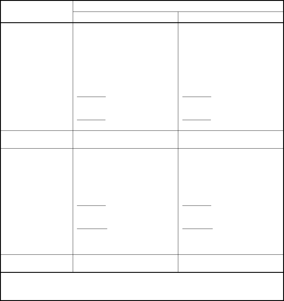
Table 4.16.9 – Flange Stress Acceptance Criteria
Flange Type Stress Acceptance Criteria
Operating Condition Gasket Seating Conditions
Integral Type Flange or
Loose Type Flange with
a Hub
min 1.5 , 2.5 (1)
Hfono
SSS
⎡⎤
≤
⎣⎦
1.5 (2)
Hfo
SS≤
Rfo
SS≤
Tfo
SS≤
()
2
HR
f
o
SS
S
+
≤
()
2
HT
f
o
SS
S
+
≤
min 1.5 , 2.5 (1)
Hfgng
SSS
⎡⎤
≤
⎣⎦
1.5 (2)
Hfg
SS
≤
Rfg
SS
≤
Tfg
SS
≤
(
)
2
HR
f
g
SS
S
+
≤
(
)
2
HT
f
g
SS
S
+
≤
Loose Type Flange
without a Hub
Tfo
SS≤
Tfg
SS
≤
Reverse Integral Type
Flange or Reverse
Loose Type Flange with
a Hub
1.5
H
fo
SS≤
Rfo
SS≤
1Tfo
SS≤
()
2
HR
f
o
SS
S
+
≤
()
1
2
HT
f
o
SS
S
+
≤
2Tfo
SS≤
1.5
H
fg
SS
≤
Rfg
SS
≤
1Tfg
SS
≤
(
)
2
HR
f
g
SS
S
+
≤
(
)
1
2
HT
f
g
SS
S
+
≤
2Tfg
SS
≤
Reverse Loose Type
Flanges
Tfo
SS≤
Tfg
SS
≤
Notes:
1. For integral flanges with hubs welded to a nozzle neck, pipe, or vessel shell
2. For loose type flanges with a hub.
3. Flanges made of non-ductile material, such as cast iron, are not addressed by this section.
2010 SECTION VIII, DIVISION 2
4-326
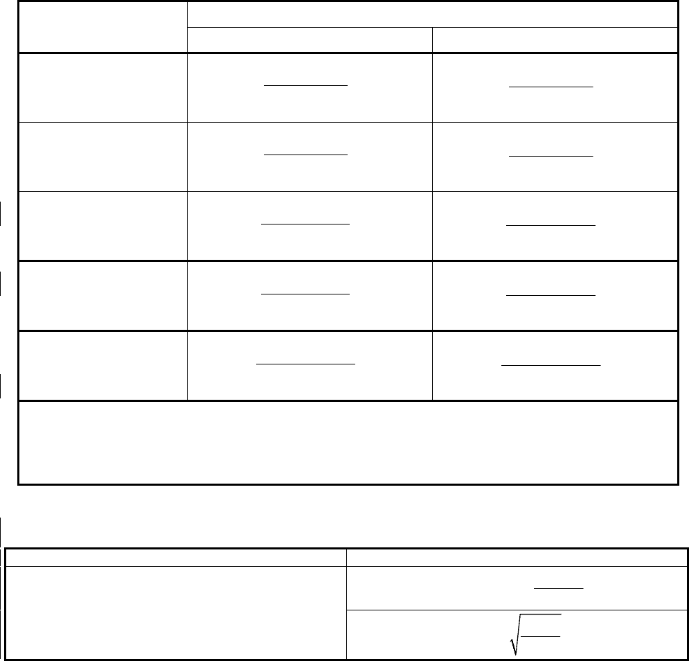
Table 4.16.10 – Flange Rigidity Criterion
Flange Type Rigidity Criterion
Operating Condition Gasket Seating Conditions
Integral Type Flange
2
0
52.14
1.0
o
yo R o
VM
J
LE g K h
=≤
2
0
52.14
1.0
g
yg R o
VM
J
LE g K h
=≤
Loose Type Flange with
a Hub
2
0
52.14
1.0
Lo
yo R o
VM
J
LE g K h
=≤
2
0
52.14
1.0
Lg
yg R o
VM
J
LE g K h
=≤
Reverse Integral Type
Flange
2
0
52.14
1.0
o
ryo Ro
VM
J
LE g K h
=≤
2
0
52.14
1.0
g
ryg Ro
VM
J
LE g K h
=≤
Reverse Loose Type
Flange with a Hub
2
0
52.14
1.0
Lo
ryo Ro
VM
J
LE g K h
=≤
2
0
52.14
1.0
Lg
ryg Ro
VM
J
LE g K h
=≤
Loose Type and
Reverse Loose Type
Flange without a Hub
()
3
109.4
1.0
ln
o
yo R
M
J
EtK K
=≤
()
3
109.4
1.0
ln
g
yg R
M
J
EtK K
=≤
Notes:
1. For an integral type flange, 0.3
R
K = unless other values are specified by the user.
2. For a loose type flange with or without a hub, 0.2
R
K
=
unless other values are specified by the
user.
Table 4.16.11 - Bolt Spacing Equations
Flange Type Bolt Spacing Factors
All
max
6
2
0.5
s
t
Ba
m
=+
+
2
s
sc
B
B
at
=
+
标准分享网 www.bzfxw.com 免费下载
2010 SECTION VIII, DIVISION 2
4-327
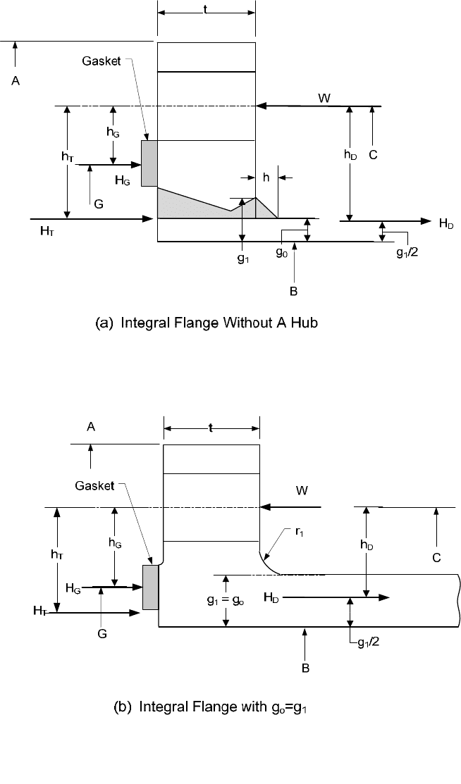
4.16.14 Figures
Figure 4.16.1 – Integral Type Flanges
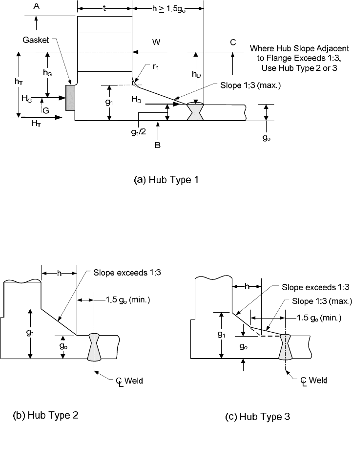
2010 SECTION VIII, DIVISION 2
4-328
Figure 4.16.2 – Integral Type Flanges with a Hub
标准分享网 www.bzfxw.com 免费下载
2010 SECTION VIII, DIVISION 2
4-329
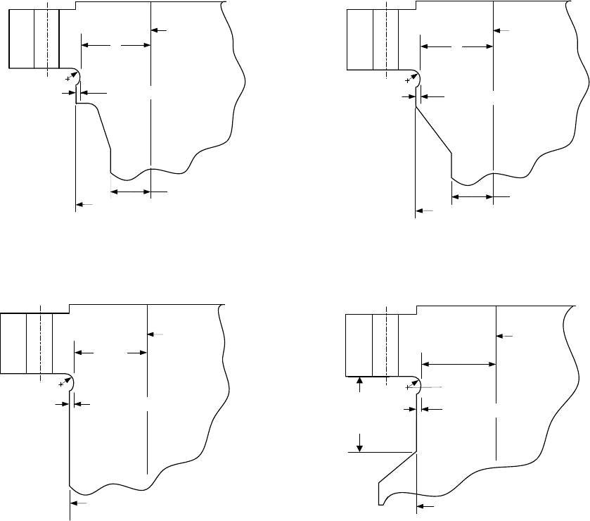
g
1
Inside
Diameter
r = 6 mm (0.25 in)
5 mm (0.1875 in)
g
o
Nut Stop Diameter
g
1
Inside
Diameter
r = 6 mm (0.25 in)
5 mm (0.1875 in)
g
o
Nut Stop Diameter
g
1
= g
0
Inside
Diameter
r = 6 mm (0.25 in)
Nut Stop Diameter
5 mm (0.1875 in)
g
1
= g
0
Inside
Diameter
r = 6 mm (0.25 in)
5 mm (0.1875 in)
Nut Stop Diameter
(a) Detail A
(b) Detail B
(c) Detail C
(d) Detail D
For Integrally
Reinforced Nozzles,
min.=Nut Height+6 mm (0.25 in)
Figure 4.16.3 – Integral Type Flanges With Nut Stops – Diameter Less Than or Equal To 450mm (18
Inches)
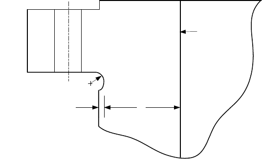
2010 SECTION VIII, DIVISION 2
4-330
g
1
Inside
Diameter
r = 10 mm (0.375 in)
8 mm (0.3125 in)
Note: All other details per Figure 4.16.3
Figure 4.16.4 – Integral Type Flanges With Nut Stops – Diameter Greater Than 450mm (18 Inches)
标准分享网 www.bzfxw.com 免费下载
2010 SECTION VIII, DIVISION 2
4-331
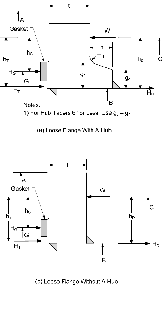
Figure 4.16.5 – Loose Type Flanges
2010 SECTION VIII, DIVISION 2
4-332
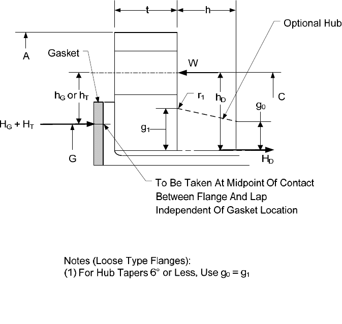
Figure 4.16.6 – Loose Type Lap Joint Type Flanges
标准分享网 www.bzfxw.com 免费下载
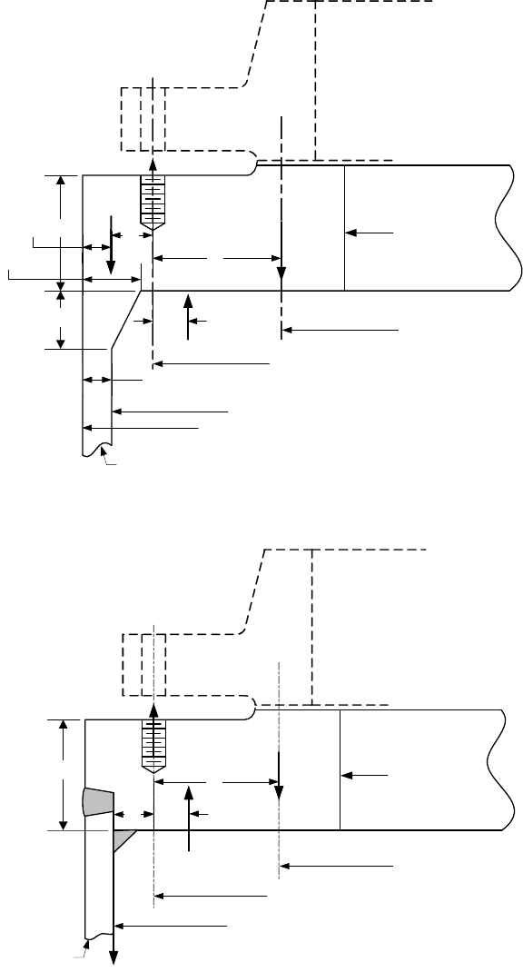
2010 SECTION VIII, DIVISION 2
4-333
H
G
B*
W
g
o
t
h
Shell
A
B
C
G
h
G
g
1
h
T
H
T
H
D
H
G
B*
W
t
Shell
A = B
C
G
h
G
h
T
H
T
H
D
(a) Integral Type Reverse Flange
(b) Loose Type Reverse Flange
g
1
/2
h
D
h
D
Figure 4.16.7 – Reverse Flanges
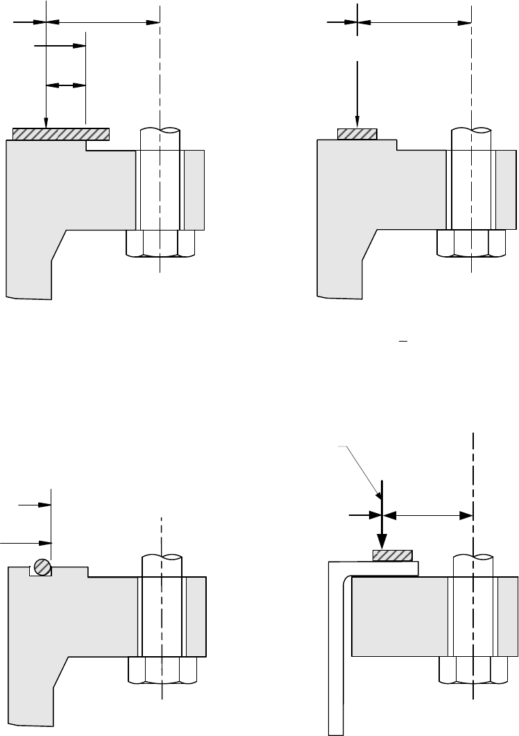
2010 SECTION VIII, DIVISION 2
4-334
G
c
= OD Contact Face
b
H
G
h
G
G
For b
o
> 6 mm (0.25in.) For b
o
< 6 mm (0.25in.)
H
G
h
G
C
L
G
Gasket Face
OD of Gasket
G
Self-Energizing Gaskets Lap Type Joints
H
T
+ H
G
G
To Be Taken At Midpoint Of Contact
Between Flange And Lap
Independent Of Gasket Location
h
T
or h
G
Figure 4.16.8 – Location of Gasket Reaction Load Diameter
标准分享网 www.bzfxw.com 免费下载
