ASME Section VIII div 2 2010. ASME Boiler and Pressure Vessel Code. Alternative Rules
Подождите немного. Документ загружается.

2010 SECTION VIII, DIVISION 2
4-275
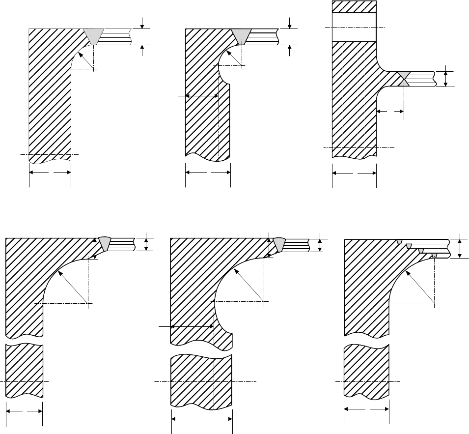
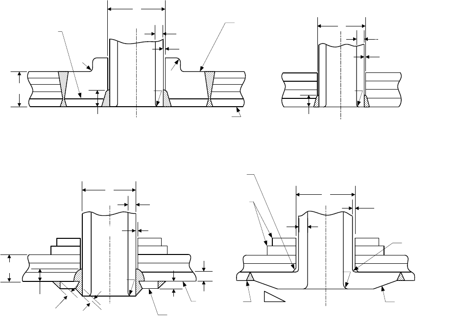
Figure 4.13.5 – Some Acceptable Solid Head Attachments to Layered Shell Sections (Continued)
t
t
S
t
e
r
r
t
S
t
(a) (b)
(c)
t
S
h
t
S
r
t
t
t
(d)
(e)
(f)
t
S
t
f
r
e
r
t
S
t
f
Figure 4.13.6 – Some Acceptable Flat Heads and Tubesheets With Hubs Joining Layered Shell
Sections
2010 SECTION VIII, DIVISION 2
4-276
Weld Line
t
S
t
S
3
1
(a)
(b)
t
S
t
S
(c)
(d)
Weld Line
3
1
3
1
Retaining
Ring
(e-1)
3
1
Weld Overlay 15% Bolt Dia. Min.
But Not Less Than 9 mm (0.375 In.)
(e) (f) (f-1)
Retaining
Ring
Weld Line
Optional
(g)
Retaining
Ring
Weld Line
Optional
(g-1)
(e),(e-1),(f),(f-1)(g),(g-1)
Weld Line
Optional
3
1
3
1
3
1
Weld Line
Optional
Tapped
Holes
Notes:
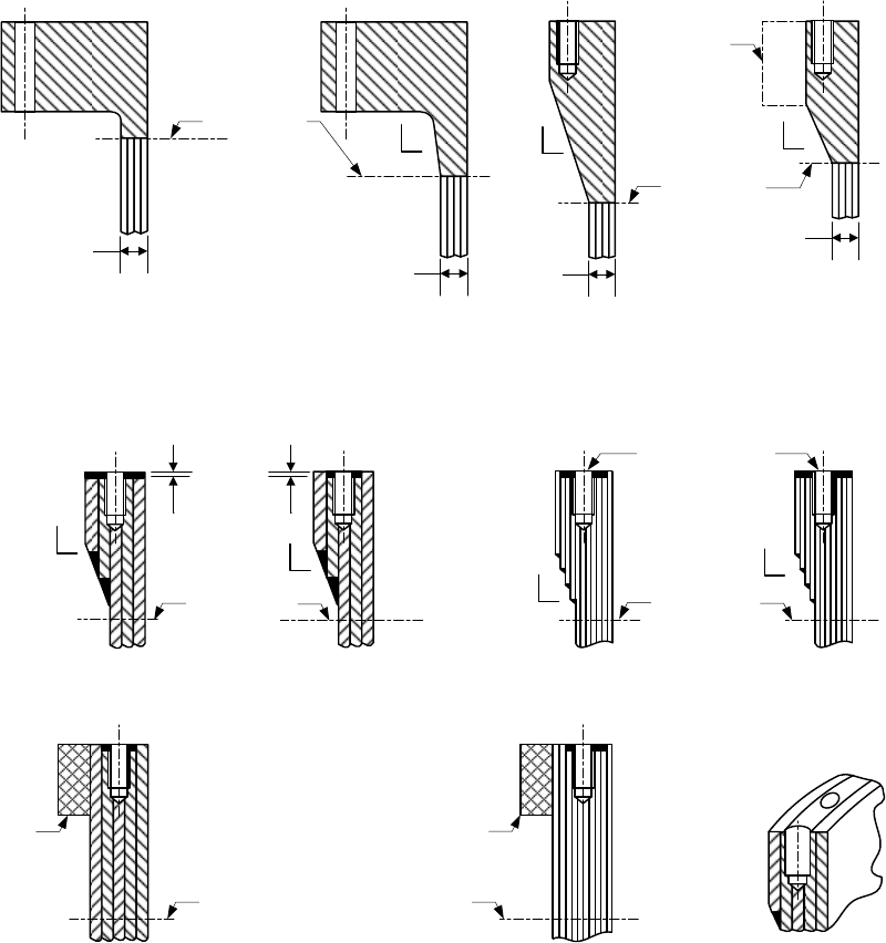
1. The following applies to Sketches (e), (e-1), (f), (f-1), (g), and (g-1): the weld overlay shall tie the overlay,
the overwraps, and layers together, and the bolt circle shall not exceed the outside diameter of the shell.
2. For Sketches (e), (e-1), (f), and (f-1), the angle of the transition and size of the fillet welds are optional,
and the bolt circle shall not exceed the outside diameter of the shell.
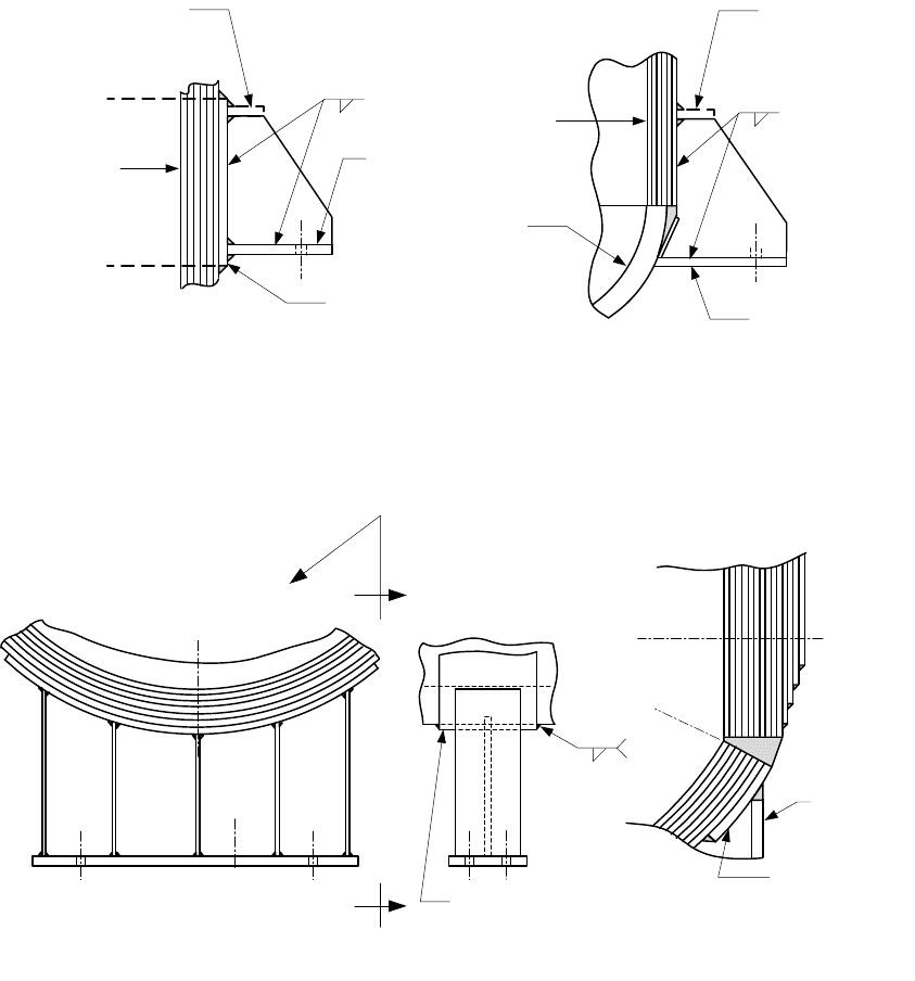
Figure 4.13.7 – Some Acceptable Flanges for Layered Shells
标准分享网 www.bzfxw.com 免费下载
2010 SECTION VIII, DIVISION 2
4-277
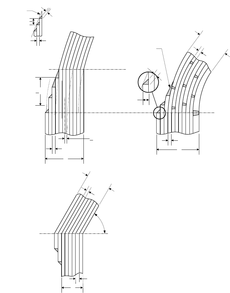
0.7 t
L
min.
3 t
L
Min.
t
L
Taper Line
< 1/2 (t
S
- t
H
)
a > 3 Y
t
L
60° Min.
t
S
Weld Line
(Category B)
(b-1)
t
H
t
L
t
L
t
S
t
L
t
S
Butt Weld Line
(Category A)
t
H
t
L
(a-2)
(a-1)
3:1 Taper
t
L
0.7 t
L
min.
Detail Of Taper
Figure 4.13.8 – Some Acceptable Layered Head Attachments to Layered Shells
2010 SECTION VIII, DIVISION 2
4-278
t
c
t
S
t
n
r
2
r
2
r
2
r
1
3:1 Taper Min.
t
S
t
n
(f) (g) (h)
t
S
3:1 Taper Min.
r
2
r
1
t
n
r
2
r
2
r
1
r
3
Backing Strip
If Used Shall
Be Removed
t
S
t
n
r
1
t
n
t
c
r
1
t
S
r
1
t
c
t
S
t
n
t
n
t
c
r
1
t
S
t
c
t
S
r
1
t
n
r
3
(e)
(d)
(c-2)
(a) (b) (c-1)
Section A-A
A
A
t
S
r
1
t
c
r
2
r
2
t
n
t
n
r
2
r
2
r
1
Smooth Surface
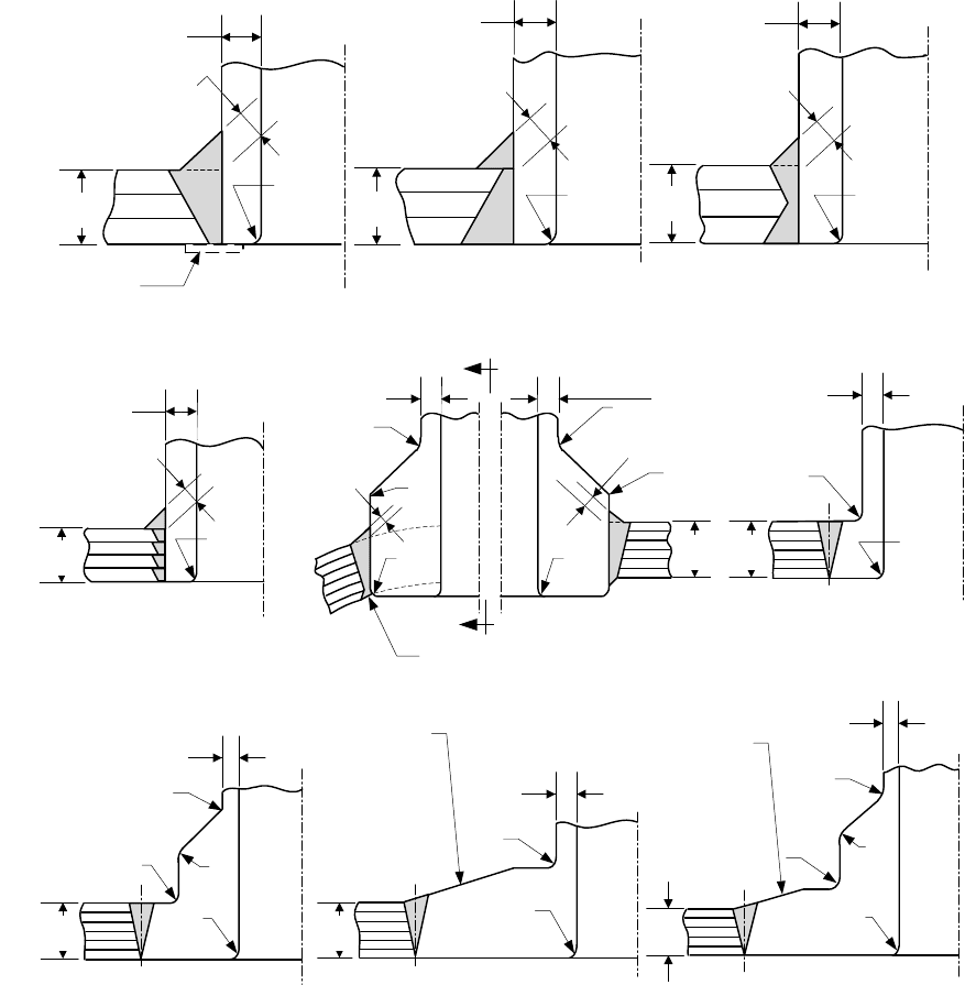
Figure 4.13.9 – Some Acceptable Nozzle Attachments to Layered Shell Sections
标准分享网 www.bzfxw.com 免费下载
2010 SECTION VIII, DIVISION 2
4-279
(j)
(i)
d*
t
S
0.5 t
L
min.
t
n
C Max.
Inner Shell
d*
t
n
C Max.
Solid Hub With
Integral
Reinforcement
r
2
Inner Shell
r
2
r
3
Vent For
Liner
1.25 t
n
Min. 1.25 t
n
Min.
d*
t
n
C Max.
r
1
d*
C Max.
t
n
Integral Nozzle
Reinforcement
r
1
r
2
Chamfer
t
S
1.25 t
n
Min.
t
c
r
1
Reinforcing Pad
t
c
t
L
Full Circumferential
Reinforcement
Layers (Over Wraps)
1
3 (min.)
(k)
(l)
Notes:
Provide a means, other than by seal welding, to prevent entry of external foreign matter into the annulus
between the layers and the nozzle neck outside diameter for Sketches (i), (j), (k), and (l).
Figure 4.13.9 – Some Acceptable Nozzle Attachments to Layered Shell Sections (Continued)
2010 SECTION VIII, DIVISION 2
4-280
Lug Or Ring
(If Necessary)
Support Lug
Or Ring
Hemi-Head
For Other Than Hemi-Heads Special
Consideration Shall Be Given To The
Discontinuity Stress
Support Ring
(If Necessary)
(a)
(b)
I.D.
Support Lug
Or Ring
Support Layer Or
Pad (If Necessary)
I.D.
Lug Or Ring
(If Necessary)
Typ.
(c) (d)
Skirt
Tangent Line
Complete Or Partial
Support Band
(If Necessary)
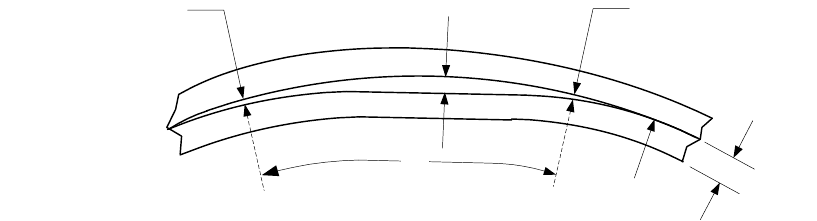
Figure 4.13.10 – Some Acceptable Supports for Layered Vessels
标准分享网 www.bzfxw.com 免费下载
2010 SECTION VIII, DIVISION 2
4-281
0.3 mm (0.010 in)
(Non-Relevant Gap)
h
0.3 mm (0.010 in)
(Non-Relevant Gap)
R
g
b
t
Figure 4.13.11 – Gap Between Vessel Layers
2010 SECTION VIII, DIVISION 2
4-282
4.14 Evaluation of Vessels Outside of Tolerance
4.14.1 Shell Tolerances
If agreed to by the user, the assessment procedures in Part 5 or in API 579-1/ASME FFS-1 may be used to
qualify the design of components that have shell tolerances that do not satisfy the fabrication tolerances in
paragraph 4.3.2 and 4.4.4. If API 579-1/ASME FFS-1 is used in the assessment, a Remaining Strength
Factor of 0.95 shall be used in the calculations unless another value is agreed to by the user. However, the
Remaining Strength Factor shall not be less than 0.90. In addition, a fatigue analysis shall be performed in
accordance with API 579-1/ASME FFS-1 as applicable.
4.14.2 Local Thin Areas
4.14.2.1 If agreed to by the user, the assessment procedures in Part 5 or in API 579-1/ASME FFS-1 may
be used to qualify the design of components that have a local thin area. A local thin area (LTA) is a region of
metal loss on the surface of the component that has a thickness that is less than required by paragraphs 4.3
and 4.4, as applicable. If API 579-1/ASME FFS-1 is used in the assessment, a Remaining Strength Factor of
0.98 shall be used in the calculations unless another value is agreed to by the user. However, the Remaining
Strength Factor shall not be less than 0.90. In addition, a fatigue analysis shall be performed in accordance
with API 579-1/ASME FFS-1 as applicable.
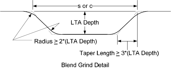
4.14.2.2 The transition between the LTA and the thicker surface shall be made with a taper length not less
than three times the LTA depth. The minimum bottom blend radius shall be equal to or greater than two
times the LTA depth (see Figure 4.14.1)
4.14.3 Marking and Reports
The Manufacturer shall maintain records of all calculations including the location and extent of the fabrication
tolerances outside the prescribed limits and/or LTAs that are evaluated using paragraph 4.14. This
information shall be provided to the user if requested and shall be included in the Manufacturer’s Design
Report.
标准分享网 www.bzfxw.com 免费下载
2010 SECTION VIII, DIVISION 2
4-283
4.14.4 Figures
Figure 4.14.1 – LTA Blend Radius Requirements
2010 SECTION VIII, DIVISION 2
4-284
4.15 Design Rules for Supports and Attachments
4.15.1 Scope
The rules in paragraph 4.15 cover requirements for the design of structural support system(s) for vessels.
The structural support system may be, but not limited to, saddles for a horizontal vessel, a skirt for a vertical
vessel, or lug and leg type supports for either of these vessel configurations.
4.15.2 Design of Supports
4.15.2.1 Vessels shall be supported for all specified design conditions. The design conditions including
load and load case combinations defined in paragraph 4.1.5.3 shall be considered in the design of all vessel
supports.
4.15.2.2 Unless otherwise defined in this paragraph, if a stress analysis of the vessel and support
attachment configuration is performed, the stress results in the vessel and in the support within the scope of
this Division shall satisfy the acceptance criteria in Part 5.
4.15.2.3 The vessel support attachment shall be subject to the fatigue screening criteria of paragraph
5.5.2. In this evaluation, supports welded to the vessel may be considered as integral attachments.
4.15.2.4 All supports shall be designed to prevent excessive localized stresses due to deformations
produced by the internal pressure or to thermal gradients in the vessel and support system.
4.15.2.5 Vessel support systems composed of structural steel shapes shall be designed in accordance
with a recognized code or standard that cover structural design (e.g. Specification for Structural Steel
Buildings
published by the American Institute of Steel Construction). If the support is at a temperature above
ambient due to vessel operation and the recognized code or standard does not provide allowable stresses at
temperatures above ambient conditions, then the allowable stress, yield strength, and ultimate tensile
strength, as applicable, shall be determined from Annex 3.A and Annex 3.D using a material with a similar
minimum specified yield strength and ultimate tensile strength.
4.15.2.6 Attachment welds for structural supports shall be in accordance with paragraph 4.2.
4.15.2.7 Reinforcing plates and saddles attached to the outside of a vessel shall be provided with at least
one vent hole that may be tapped for a preliminary compressed air and soap solution (or equivalent) test for
tightness of welds that seal the edge of the reinforcing plates and saddles. These vent holes may be left
open or may be plugged when the vessel is in service. If the holes are plugged, the plugging material used
shall not be capable of sustaining pressure between the reinforcing plate and the vessel wall. Vent holes
shall not be plugged during heat treatment.
4.15.2.8 If nonpressure parts such as support lugs, brackets, leg supports and saddles extend over
pressure retaining welds, then these welds shall be ground flush for the portion of weld that is covered, or the
nonpressure parts shall be notched or coped to clear these welds.
4.15.3 Saddle Supports for Horizontal Vessels
4.15.3.1 Application of Rules
a) Design Method – The design method in this paragraph is based on an analysis of the longitudinal
stresses exerted within the cylindrical shell by the overall bending of the vessel, considered as a beam
on two single supports, the shear stresses generated by the transmission of the loads on the supports,
and the circumferential stresses within the cylindrical shell, the head shear and additional tensile stress
in the head, and the possible stiffening rings of this shell, by this transmission of the loads on the
supports. The stress calculation method is based on linear elastic mechanics and covers modes of
标准分享网 www.bzfxw.com 免费下载