ASME Section VIII div 2 2010. ASME Boiler and Pressure Vessel Code. Alternative Rules
Подождите немного. Документ загружается.

2010 SECTION VIII, DIVISION 2
4-265
4.13.11 Vent Holes
4.13.11.1 Vent holes shall be provided to detect leakage of the inner shell and to prevent buildup of
pressure within the layers as follows.
4.13.11.2 In each shell course or head segment, a layer may be made up of one or more plates. Each
layer plate shall have at least two vent holes 6 mm (0.25 in.) minimum diameter. Holes may be drilled radially
through the multiple layers or may be staggered in individual layer plates.
4.13.11.3 For continuous coil wrapped layers, each layered section shall have at least four vent holes 6 mm
(0.25 in.) minimum diameter. Two of these vent holes shall be located near each end of the section and
spaced approximately 180 deg apart.
4.13.11.4 The minimum requirement for spirally wound strip layered construction shall be 6 mm (0.25 in.)
minimum diameter vent holes drilled near both edges of the strip. They shall be spaced for the full length of
the strip and shall be located a distance of approximately
/tanR
π
θ
from each other (where
R
is the mean
radius of the shell and
θ
is the acute angle of spiral wrap measured from the longitudinal centerline, deg).
4.13.11.5 If a strip weld covers a vent hole, partially or totally, an additional vent hole shall be drilled on
each side of the obstructed hole.
4.13.11.6 In addition to the above, holes may be drilled radially through the multiple layers.
4.13.11.7 Vent holes shall not be obstructed. If a monitoring system is used, it shall be designed to prevent
buildup of pressure within the layers.
4.13.12 Shell Tolerances
4.13.12.1 Contact Between Layers
The following requirements shall be satisfied.
a) Category A weld joints shall be ground to ensure contact between the weld area and the succeeding
layer, before application of the layer.
b) Category A weld joints of layered shell sections shall be in an offset pattern so that the centers of the
welded longitudinal joints of adjacent layers are separated circumferentially by a distance of at least five
times the layer thickness.
c) Category A weld joints in layered heads may be in an offset pattern; if offset, the joints of adjacent layers
shall be separated by a distance of at least five times the layer thickness.
d) After weld preparation and before welding circumferential seams, the height of the radial gaps between
any two adjacent layers shall be measured at the ends of the layered shell section or layered head
section at right angles to the vessel axis, and also the length of the relevant radial gap in inches shall be
measured (neglecting radial gaps of less than 0.25 mm (0.010 in.) as non relevant). The gap area,
g
A ,
shall not exceed the thickness of a layer expressed in square inches. An approximation of the area of
the gap shall be calculated using Equation (4.13.2). The maximum length of any gap shall not exceed
the
inside diameter of the vessel. Where more than one gap exists between any two adjacent layers, the
sum of the gap lengths shall not exceed the inside diameter of the vessel. The maximum height of any
gap shall not exceed 4.8 mm (0.1875 in.). It is recognized that there may be vessels of dimensions
wherein it would be desirable to calculate a maximum permissible gap area, and also when cyclical
service conditions require it. This procedure is provided in paragraph 4.13.12.2 and may be used in lieu
of the maximum gap area given above, (see Figure 4.13.11).
2010 SECTION VIII, DIVISION 2
4-266
2
3
g
Abh= (4.13.2)
e) In the case of layered spheres or layered heads, if the gaps cannot be measured as required in
paragraph 4.13.12.1.d, measurement of gap heights shall be taken through vent holes in each layer
course to assure that the height of layer gaps between any two layers does not exceed the gap
permitted in paragraph 4.13.12.1.d. The spacing of the vent holes shall be such that gap lengths can be
determined. In the event an excessive gap height is measured through a vent hole, additional vent holes
shall be drilled as required to determine the gap length. There shall be at least one vent hole per layer
segment.
4.13.12.2 Alternative to Measuring Contact between Layers During Construction
As an alternative to paragraph 4.13.12.1.d, the following measurements shall be taken at the time of the
hydrostatic test to check on the contact between successive layers, and the effect of gaps which may or may
not be present between layers.
a) The circumference shall be measured at the midpoint between adjacent circumferential joints, or
between a circumferential joint and any nozzle in a shell course. Measurements shall be taken at zero
pressure and, following application of hydrostatic test pressure, at the design pressure. The difference
in measurements shall be averaged for each course in the vessel and the results recorded as average
middle circumferential expansion,
m
e .
b) The theoretical circumferential expansion of a solid vessel of the same dimensions and materials as the
layered vessel shall be calculated from Equation (4.13.3). The acceptance criterion for circumferential
expansion at the design pressure is:
0.5
mth
ee≥ .
()()
2
1.7 2 2
8
ms ms
th
yms
PR t R t
e
ERt
π
−+
=
(4.13.3)
4.13.12.3 Rules for Calculating Maximum Permissible Gaps
The maximum number and size of gaps permitted in any cross section of a layered vessel shall be limited by
paragraphs 4.13.12.3.a and 4.13.12.3.b.
a) Maximum gap between any two layers shall not exceed the value of
h given by Equation (4.13.4):
0.55 0.5
g
m
my
R
S
P
hN
SE
⎛⎞
=−−
⎜⎟
⎝⎠
(4.13.4)
where,
3N for infinite cycles= (4.13.5)
2
a
cm
S
N for a specified number of cycles
KS
⎛⎞
=
⎜⎟
⎝⎠
(4.13.6)
with,
4
0.25 0.5
3
a
c
m
S
K
S
=+−
(4.13.7)
标准分享网 www.bzfxw.com 免费下载

2010 SECTION VIII, DIVISION 2
4-267
b) Maximum permissible number of gaps and their corresponding arc lengths at any cross section of a
layered vessel shall be calculated as follows.
1) Measure each gap and its corresponding length throughout the cross section.
2) Calculate the value of
F for each of the gaps using the following equation:
2
0.109
g
bh
F
R
⎛⎞
=
⎜⎟
⎜⎟
⎝⎠
(4.13.8)
3) The total sum of the calculated
F values shall not exceed the quantity
2
2
22
2
1
o
Tm
yoi
PR
v
FNS
ERR
⎛⎞
−
=−
⎜⎟
−
⎝⎠
(4.13.9)
4.13.13 Nomenclature
g
A gap area.
b length of the gap between any two layers.
C equal to 3 mm (0.125 in.) radial clearance between the nozzle neck and vessel opening
*
d
finished opening in the wall
th
e theoretical circumferential expansion.
m
e average middle recorded circumferential expansion.
F gap value.
T
F total permissible gap value.
y
E Modulus of Elasticity for the layer material from Part 3 .
h gap between any two layers.
ν
Poisson's ratio.
P design pressure of the vessel.
g
R
outside radius of the layer above where the gap is located.
i
R
inside radius of the vessel.
m
R
mean radius of the vessel.
o
R
outside radius of the vessel.
a
S stress amplitude from the applicable fatigue curve for the layer material from Annex 3.F .
L
S allowable stress for the layers from Annex 3.A at the design temperature.
i
S allowable stress for the inner layer from Annex 3.A at the design temperature.
m
S allowable stress for the layer material from Annex 3.A at the design temperature.
1
r equal to
(
)
min 0.25 ,3 0.125
n
tmm in⎡⎤
⎣⎦
2
r equal to 6 mm (0.25 in.) minimum
3
r equal to
(
)
min 0.25 ,19 0.75
n
tmm in⎡⎤
⎣⎦
t actual thickness of the head or tubesheet or for nozzle details equal to
[
]
min , 19 (0.75 .)
n
tmm in, as applicable.
2010 SECTION VIII, DIVISION 2
4-268
act
t actual thickness of inner shell or inner head.
c
t equal to the larger of 6 mm (0.25 in.) or
[
]
0.7 min , 19 (0.75 .)
n
tmm in
eff
t effective thickness of inner shell or inner head.
H
t thickness of the head at the head-to-cylinder joint.
L
t thickness of the layer.
n
t nominal thickness of the nozzle wall less corrosion allowance
S
t total wall thickness of the layered vessel.
Y offset.
标准分享网 www.bzfxw.com 免费下载
2010 SECTION VIII, DIVISION 2
4-269
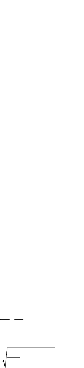
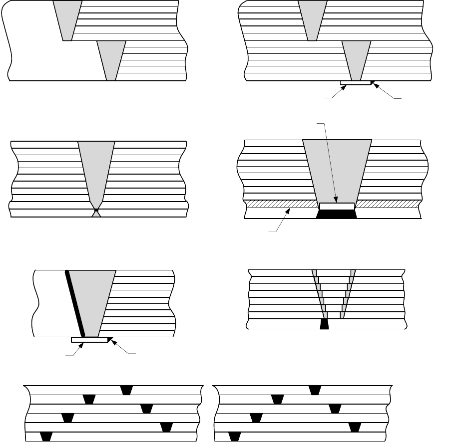
4.13.14 Figures
(a) Concentric Wrapped
Note (1)
Note (3)
Note (2)
(b) Coil Wound
Note (1)
Note (3)
Note (2)
(c) Shrink Fit
Note (1)
Note (3)
Note (2)
(d) Spiral Wrapped
Note (1)
Note (4)
Note (2)
Note (5)
Note (6)
Notes:
1. Inner shell
2. Dummy layer (if used)
3. Layers
4. Shell layer (tapered)
5. Balance of layers
6. Gap
Figure 4.13.1 – Some Acceptable Layered Shell Types
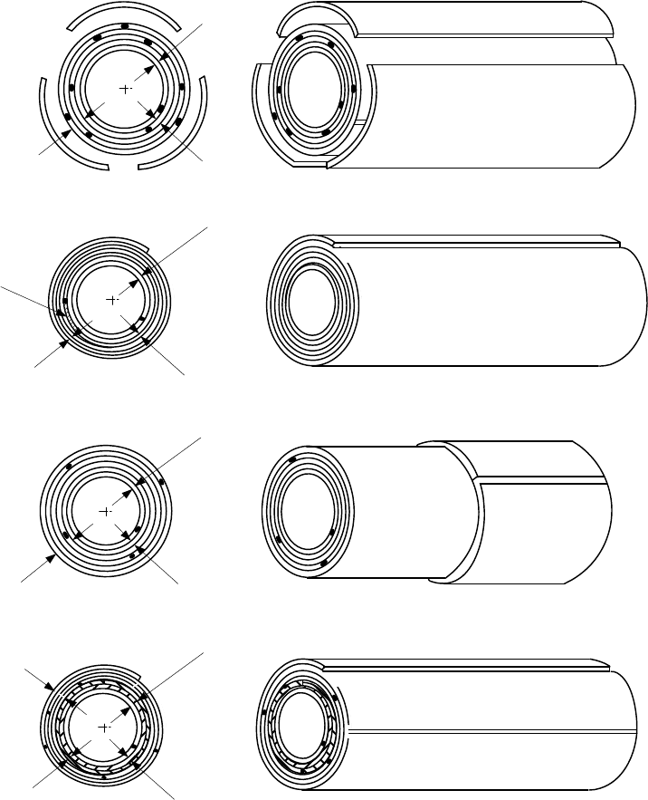
2010 SECTION VIII, DIVISION 2
4-270
Note (1)
Segmental
Note (2)
Note (3)
Note (1)
Note (2)
Note (3)
(a)
Press Fit
(c)
(b)
Note (1)
Note (2)
Note (3)
(b)
(d)
Note (1)
Note (2)
Note (3)
Notes:
1. Inner head
2. Dummy layer (if used)
3. Head layers
Figure 4.13.2 – Some Acceptable Layered Head Types
标准分享网 www.bzfxw.com 免费下载
2010 SECTION VIII, DIVISION 2
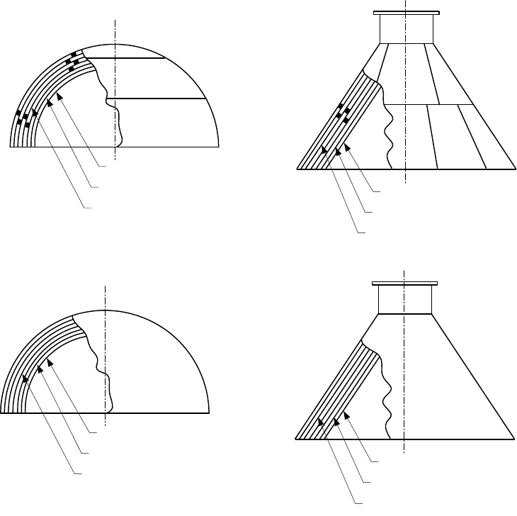
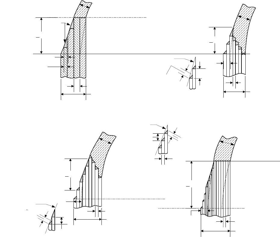
4-271
t
L
a
Details Of Taper For Layers 16 mm
(0.625 in.) Or Less In Thickness
(b)
Weld Line (Category B)
For Layers Over 16 mm (0.625 in.)
Thickness
(a)
t
L
Taper Line
3t
L
min.
Weld Optional
0.7 t
L
min.
Weld Line (Category B)
Optional Weld Line (Category B)
For Layers 16 mm (0.625 in.) Or Less
In Thickness
(d)
For Layers Over 16 mm (0.625 in.)
Thickness
(c)
For Layers 16 mm (0.625 in.) Or Less
In Thickness
(f)
For Layers Over 16 mm (0.625 in.)
Thickness
(e)
Weld Optional
a
2/3 t
L
Min.
t
L
or Y
3:1 Taper Min. See Detail
Sketch (b)
3:1 Taper. See Sketch (b)
Note: Taper May Be Inside
Or Outside Or Both.
3:1 Taper Min.3:1 Taper Min.
Notes:
1.
3aY≥ where a is the required length of the taper and Y is the offset.
2. The length of the required taper may include the width of the weld.
3. The transition may be on either or both sides.
Figure 4.13.3 – Transitions of Layered Shell Sections
2010 SECTION VIII, DIVISION 2
4-272
Tack Weld
Backing Strip
(g) Butt Girth Welds
Tack Weld
Backing Strip
(e)
(f)
(d)
(c)
Dummy Layer
(b)
(a)
Dummy Insert
Figure 4.13.4 – Some Acceptable Welded Joints of Layered-To-Layered and Layered-To-Solid
Sections
标准分享网 www.bzfxw.com 免费下载
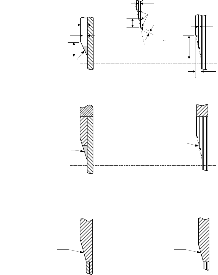
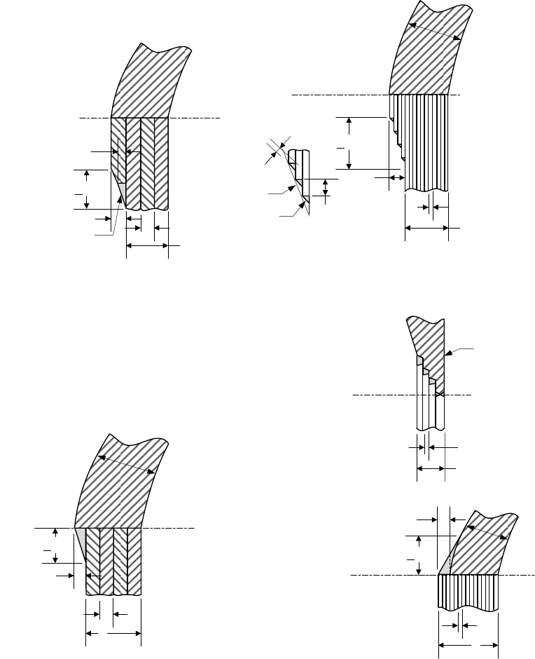
2010 SECTION VIII, DIVISION 2
4-273
t
L
t
S
a > 3 Y
t
L
a > 3 Y
t
H
0.7 t
L
min.
t
S
3 t
L
Min.
Hemispherical
Heads Only
Taper Line
Tangent Line
Y
Details Of Taper For
Layers 22 mm (0.875 in.) Or Less In
Thickness
(b-1)
For Layers 16 mm (0.625 in.)
Thickness
(a)
t
L
t
S
Weld
Butt Weld Line
(Category A)
t
H
Y
2/3 t
L
Min. For
Chamfered Layers
Details Of Taper For
Layers 16 mm (0.625 in.) Or Less In
Thickness
(b-3)
Details Of Taper For
Layers 22 mm (0.875 in.) Or Less
In Thickness
(b-2)
0.7 t
L
min.
3 t
L
Min.
Taper Line
t
H
a > 3 Y
a > 3 Y
Butt Weld Line
(Category A)
t
H
t
L
t
S
Y
Tangent Line
Tangent Line
Hemispherical
Heads Only
Y
0.7 t
L
min.
3 t
L
Min.
t
L
Taper Line
Figure 4.13.5 – Some Acceptable Solid Head Attachments to Layered Shell Sections
2010 SECTION VIII, DIVISION 2
4-274
t
H
0.7 t
L
min.
3 t
L
Min.
Y
t
H
t
H
Butt Weld Line May Be At Or Below
Tangent Line Depending On Code
Requirement For Type Of Head And Weld
t
L
a > 3 Y
t
S
Y
Tangent Line
Tangent Line
For Layers Over 16 mm (0.625 in.)
Thickness
(c)
Details Of Taper For Layers Over
16 mm (0.625 in.) Thickness
(d-1)
Inside
Inner Shell
t
L
t
S
For Layers Of Any Thickness
(f)
t
L
t
S
a > 3 Y
Butt Weld Line May Be At Or Below
Tangent Line Depending On Code
Requirements For Type Of Head
And Weld
Tangent Line
Tangent Line
a > 3 Y
Y
t
L
t
S
For Layers 16 mm (0.625 in.) Or Less In
Thickness
(e)
Permissible For Layers
22 mm (0.875 In.) Or Less In Thickness
(d-2)
Weld Line
Welds Optional
Taper Line
t
L
Y
a > 3 Y
2/3 t
L
Min.
Welds Optional
t
S
Notes:
1.
In Sketch (e),
L
Yt≤ shall be satisfied, in Sketch (f), 0.5
S
Yt
≤
shall be satisfied
2. In all cases, 3aY≥ shall be satisfied. The shell centerline may be on either side of the head centerline
by a maximum distance of
()
0.5
SH
tt− . The length of the required taper may include the width of the
weld.
3. The actual thickness shall not be less than the theoretical head thickness.
标准分享网 www.bzfxw.com 免费下载