ASME Section VIII div 2 2010. ASME Boiler and Pressure Vessel Code. Alternative Rules
Подождите немного. Документ загружается.

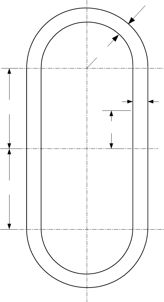
2010 SECTION VIII, DIVISION 2
4-255
t
1
Y
A
C
L
2
L
2
B
R
t
2
Notes:
1. Critical Locations of Maximum Stress are defined at points A, B, and C.
2. Defined Locations for Stress Calculations are determined using variable Y.
Figure 4.12.10 – Type 9 Noncircular Vessels
(Obround Cross Section)
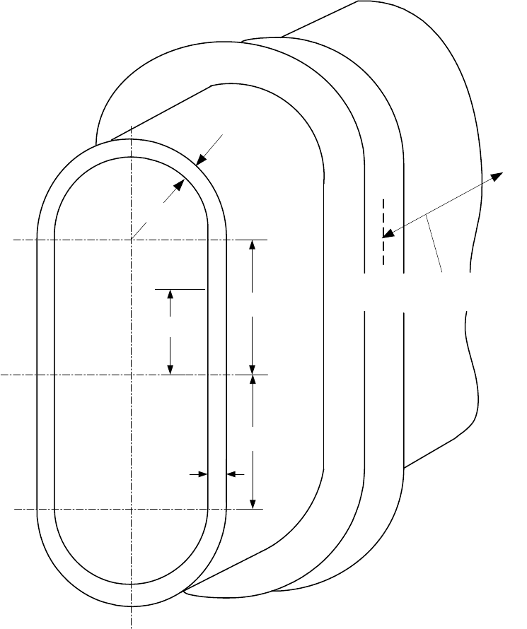
2010 SECTION VIII, DIVISION 2
4-256
t
1
= t
2
Y
A
C
L
2
L
2
B
R
t
2
Pitch Distance to Next
Reinforcing Member
Notes:
1. Critical Locations of Maximum Stress are defined at points A, B, and C.
2. Defined Locations for Stress Calculations are determined using variable Y.
Figure 4.12.11 – Type 10 Noncircular Vessels
(Reinforced Obround Cross Section)
标准分享网 www.bzfxw.com 免费下载
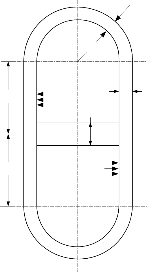
2010 SECTION VIII, DIVISION 2
4-257
t
1
t
3
Stay
A
P
P
C
L
2
L
2
B
R
t
2
Note: Critical Locations of Maximum Stress are defined at points A, B, and C.
Figure 4.12.12 – Type 11 Noncircular Vessels
(Obround Cross Section With Single Stay Plate Or Multiple Bars)
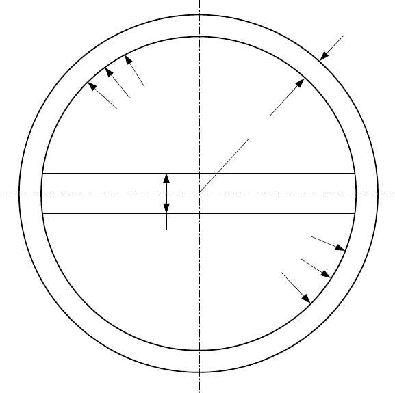
2010 SECTION VIII, DIVISION 2
4-258
R
t
1
P
1
P
2
Plate Member A
t
3
Note: Critical Locations of Maximum Stress are defined at point A.
Figure 4.12.13 – Type 12 Noncircular Vessels
(Circular Cross Section With Single Stay Plate)
标准分享网 www.bzfxw.com 免费下载
2010 SECTION VIII, DIVISION 2
4-259
t
T
o
T
1
T
2
p
h
d
O
d
1
d
2
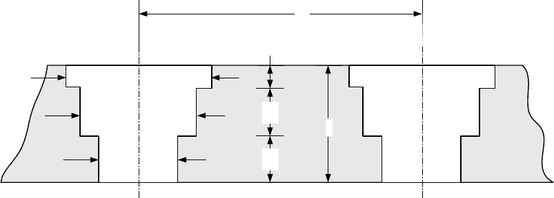
Figure 4.12.14 – Multi-Diameter Holes
2010 SECTION VIII, DIVISION 2
4-260
t
1
h/2
h/2
t
4
t
1
t
4
t
4
Stay
A
B
P
Stay
P
C
Stay
P
P
t
2
H/2
t
2
Stay
A
B
Stay
P
P
P
C
t
1
h/2
h/2
t
1
t
4
t
4
t
2
H/2
t
2
Note: Critical Locations of Maximum Stress are defined at points A, B, and C.
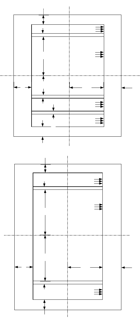
Figure 4.12.15 – Rectangular Vessels With Multiple Compartments
标准分享网 www.bzfxw.com 免费下载

2010 SECTION VIII, DIVISION 2
4-261
4.13 Design Rules for Layered Vessels
4.13.1 Scope
Design rules for layered vessels are covered in paragraph 4.13. There are several manufacturing techniques
used to fabricate layered vessels, and these rules have been developed to cover most techniques used today
for which there is extensive documented construction and operational data. Examples of acceptable layered
shell and head types are shown in Figures 4.13.1 and 4.13.2.
4.13.2 Definitions
The following terms are used in this paragraph to define components of a layered vessel.
a) Layered Vessel – a vessel having a shell and/or heads made up of two or more separate layers.
b) Inner Shell – the inner cylinder that forms the pressure tight membrane.
c) Inner Head – the inner head that forms the pressure tight membrane.
d) Shell Layer – layers may be cylinders formed from plate, sheet, forgings, or the equivalent formed by
coiling. This does not include wire winding.
e) Head Layer – anyone of the head layers of a layered vessel except the inner head.
f) Overwraps – layers added to the basic shell or head thickness for the purpose of building up the
thickness of a layered vessel for reinforcing shell or head openings, or making a transition to thicker
sections of the layered vessel.
g) Dummy Layer – a layer used as a filler between the inner shell (or inner head) and other layers, and not
considered as part of the required total thickness.
4.13.3 General
4.13.3.1 The design for layered pressure vessels shall conform to the general design requirements given
in paragraph 4.1.
4.13.3.2 A fatigue analysis in accordance with Part 5 shall be performed in all cases unless the fatigue
analysis screening based on experience with comparable equipment in accordance with paragraph 5.5.2.2 is
satisfied.
4.13.3.3 The Manufacturer's Quality Control System shall include the construction procedure that will
outline the sequence and method of application of layers and measurement of layer gaps.
4.13.4 Design for Internal Pressure
4.13.4.1 The total thickness of layered shells of revolution under internal pressure shall not be less than
that computed by the equations in paragraph 4.3.
4.13.4.2 An inner shell or inner head material that has a lower allowable design stress than the layer
materials may only be included as credit for part of the total wall thickness if
i
S is not less than 0.5
L
S by
considering its effective thickness to be:
i
eff act
L
S
tt
S
⎛⎞
=
⎜⎟
⎝⎠
(4.13.1)
2010 SECTION VIII, DIVISION 2
4-262
4.13.4.3 Layers in which the stress intensity value of the materials is within 20% of the other layers may
be used by prorating the allowable stress from Annex 3.A evaluated at the design temperature of the layers in
the thickness equation, provided the materials are compatible in modulus of elasticity and coefficient of
thermal expansion (see Part 3).
4.13.4.4 The minimum thickness of any layer shall not be less than 3.2 mm (0.125 in.).
4.13.5 Design for External Pressure
4.13.5.1 When layered shells are used for external pressure, the requirements of paragraph 4.4 shall be
applied with the following additional requirements.
a) The thickness used for establishing external pressure applied to the outer layer shall be the thickness of
the total layers, except as given in paragraph 4.13.5.1.b. The design of the vent holes shall be such that
the external pressure is not transmitted through the vent holes in the outer layer.
b) The thickness used for establishing vacuum pressure shall be only the thickness of the inner shell or
inner head.
4.13.5.2 Layered shells under axial compression shall be calculated in accordance with paragraph 4.4,
utilizing the total layered shell thickness.
4.13.6 Design of Welded Joints
4.13.6.1 The design of welded joints shall conform to the requirements given in paragraph 4.2 except as
modified herein.
4.13.6.2 Category A and B joints of inner shells and inner heads of layered sections shall be as follows.
a) Category A joints shall be Type No. 1 (see paragraph 4.2).
b) Category B joints shall be Type No. 1 or Type No. 2 (see paragraph 4.2).
4.13.6.3 Category A joints of layered sections shall be as follows.
a) Category A joints of layers over 22 mm (0.875 in.) in thickness shall be Type No. 1 (see paragraph 4.2).
b) Category A joints of layers 22 mm (0.875 in.) or less in thickness shall be of Type 1 or 2 (see paragraph
4.2), except the final outside weld joint of spiral wrapped layered shells may be a single lap weld.
4.13.6.4 Category B joints of layered shell sections to layered shell sections, or layered shell sections to
solid shell sections, shall be of Type 1 or 2 (see paragraph 4.2).
a) Category B joints of layered sections to layered sections of unequal thickness shall have transitions as
shown in Figure 4.13.3 Sketch (a) or (b).
b) Category B joints of layered sections to solid sections of unequal thickness shall have transitions as
shown in Figure 4.13.3 Sketch (c), (d), (e), or (f).
c) Category B joints of layered sections to layered sections of equal thickness shall be as shown in Figure
4.13.4 Sketch (b), (c), (d), (f), or (g).
d) Category B joints of layered sections to solid sections of equal thickness shall be as shown in Figure
4.13.4 Sketch (a) or (e).
标准分享网 www.bzfxw.com 免费下载
2010 SECTION VIII, DIVISION 2
4-263
4.13.6.5 Category A joints of solid hemispherical heads to layered shell sections shall be of Type 1 or 2
(see paragraph 4.2).
a) Transitions shall be as shown in Figure 4.13.5 Sketch (a), (b-1), (b-2), or (b-3) when the hemispherical
head thickness is less than the thickness of the layered shell section and the transition is made in the
layered shell section.
b) Transitions shall be as shown in Figure 4.13.5 Sketch (c), (d-1), or (e) when the hemispherical head
thickness is greater than the thickness of the layered shell section and the transition is made in the
layered shell section.
c) Transition shall be as shown in Figure 4.13.5 Sketch (f) when the hemispherical head thickness is less
than the thickness of the layered shell section and the transition is made in the hemispherical head
section.
4.13.6.6 Category B joints of solid elliptical, torispherical, or conical heads to layered shell sections shall
be of Type 1 or 2 (see paragraph 4.2). Transitions shall be as shown in Figure 4.13.5 Sketch (c), (d-1), (d-2),
(e), or (f).
4.13.6.7 Category C joints of solid flat heads and tube-sheets to layered shell sections shall be of Type 1
or 2 (see paragraph 4.2) as indicated in Figure 4.13.6. Transitions, if applicable, shall be used as shown in
Figure 4.13.3 Sketch (c), (d), (e), or (f).
4.13.6.8 Category C joints attaching solid flanges to layered shell sections and layered flanges to layered
shell sections shall be of Type 1 or 2 (see paragraph 4.2) as indicated in Figure 4.13.7.
4.13.6.9 Category A joints of layered hemispherical heads to layered shell sections shall be of Type 1 or 2
(see paragraph 4.2) with transition as shown in Figure 4.13.8 Sketch (a-1) or (a-2).
4.13.6.10 Category B joints of layered conical heads to layered shell sections shall be of Type 1 or 2 (see
paragraph 4.2) with transitions as shown in Figure 4.13.8 Sketch (b-1).
4.13.6.11 Category B joints of layered shell sections to layered shell sections or layered shells to solid
heads or shells may be butt joints as shown in Figure 4.13.4 Sketches (c), (d), and (e), or step welds as
shown in Figure 4.13.4 Sketches (a), (b), (f), and (g).
4.13.6.12 Category D joints of solid nozzles, manholes, and other connections to layered shell or layered
head sections shall be full penetration welds as shown in Figure 4.13.9 except as permitted in Sketch (i), (j),
(k), or (I). Category D joints between layered nozzles and shells or heads are not permitted.
4.13.6.13 When layers of Category A joints as shown in Figure 4.13.5 Sketches (a), (b-1), (b-2), and (b-3)
and Figure 4.13.8 Sketches (a-1) and (a-2) are welded with fillet welds having a taper less than 3:1, an
analysis of the head-to-shell junction shall be done in accordance with Part 5. Resistance due to friction shall
not be considered in the analysis. The longitudinal load resisted by the weld shall consider the load
transferred from the remaining outer layers.
4.13.7 Nozzles and Nozzle Reinforcement
4.13.7.1 All openings, except as provided in paragraph 4.13.7.2 shall meet the requirements for
reinforcing per paragraph 4.5. All reinforcements required for openings shall be integral with the nozzle or
provided in the layered section or both. Additional layers may be included for required reinforcement.
4.13.7.2 Openings, DN 50 (NPS 2) and smaller, need not be reinforced when installed in layered
construction but may be welded on the inside as shown in Figure 4.13.9 Sketch (j). The nozzle nominal wall
thickness shall not be less than Schedule 80 pipe as fabricated in addition to meeting the requirements of
paragraph 4.5.5.
2010 SECTION VIII, DIVISION 2
4-264
4.13.7.3 Some acceptable nozzle geometries and attachments are shown in Figure 4.13.9.
4.13.7.4 Openings up to and including 6 in. nominal pipe size (DN 150) may be constructed as shown in
Figure 4.13.9 Sketches (k) and (I). Such partial penetration weld attachments may only be used for
instrumentation openings, inspection openings, etc. on which there are no external mechanical loadings
provided the following requirements are met.
a) The requirements for reinforcing specified in paragraph 4.13.7 apply except that the diameter of the
finished openings in the wall shall be
*
d as specified in Figure 4.13.9 Sketches (k) and (l), and the
thickness
r
t is the required thickness of the layered shells computed by the design requirements.
b) Additional reinforcement, attached to the inside surface of the inner shell, may be included after the
corrosion allowance is deducted from all exposed surfaces. The attachment welds shall comply with
paragraph 4.2 and Figure 4.13.9 Sketch (k) or (I).
c) Metal in the nozzle neck available for reinforcement shall be limited by the boundaries specified in
paragraph 4.5 except that the inner layer shall be considered the shell.
4.13.7.5 Openings greater than 51 mm (2 in.) may be constructed as shown in Figure 4.13.9 Sketch (i).
The requirements for reinforcing specified in paragraph 4.13.7.4.a apply except that:
a) The diameter of the finished openings in the walls shall be d' as specified in Figure 4.13.9 Sketch (i), and
the thickness
r
t
is the required thickness of the layered shells computed by the design requirements;
b) Additional reinforcement may be included in the solid hub section as shown in Figure 4.13.9 Sketch (i);
c) Metal in the nozzle neck available for reinforcement shall be limited by the boundaries specified in
paragraph 4.5, except that the inner layer shall be considered the shell.
4.13.8 Flat Heads
4.13.8.1 Design criteria shall meet the requirements of paragraph 4.6.
4.13.8.2 The design of welded joints shall be in accordance with paragraph 4.13.6.
4.13.9 Bolted and Studded Connections
4.13.9.1 Design criteria shall meet the requirements of paragraph 4.16.
4.13.9.2 The design of welded joints shall be in accordance with paragraph 4.13.6.
4.13.10 Attachments and Supports
4.13.10.1 Supports for layered pressure vessels may be designed in accordance with paragraph 4.15.
Examples of some acceptable supports are shown in Figure 4.13.10.
4.13.10.2 When attaching supports or other connections to the outside or inside of layered pressure
vessels, only the immediate layer shall be used in the calculation, except where provisions are made to
transfer the load to other layers.
4.13.10.3 When jacketed closures are used, provisions shall be made for extending layer vents through the
jacket (see paragraph 4.13.11.1). Partial jackets covering only a portion of the circumference are not
permitted on layered shells.
标准分享网 www.bzfxw.com 免费下载
