ASM Metals HandBook Vol. 8 - Mechanical Testing and Evaluation
Подождите немного. Документ загружается.

Traditionally, flat plate impact tests have been used to obtain high strain rate yield data, shock wave response
data, and equation of state data for materials undergoing uniaxial strain. Uniaxial strain refers to a three-
dimensional state of stress in which deformation or strain occurs in only one direction—the direction of
loading. The uniaxial strain condition persists for only a short period of time until stress waves originating at
lateral boundaries reach the specimen interior. In a typical experiment, this time period is on the order of
several to tens of microseconds. Uniaxial strain is defined mathematically as:
u
x
≠ 0, u
y
= u
z
= 0
(Eq 19)
where x is the direction of loading, u
x
is the displacement in that direction, and y and z are orthogonal directions
in a plane normal to x. The strains are obtained from the displacement derivatives, thus:
ε
x
≠ 0, ε
y
= ε
z
= 0
(Eq 20)
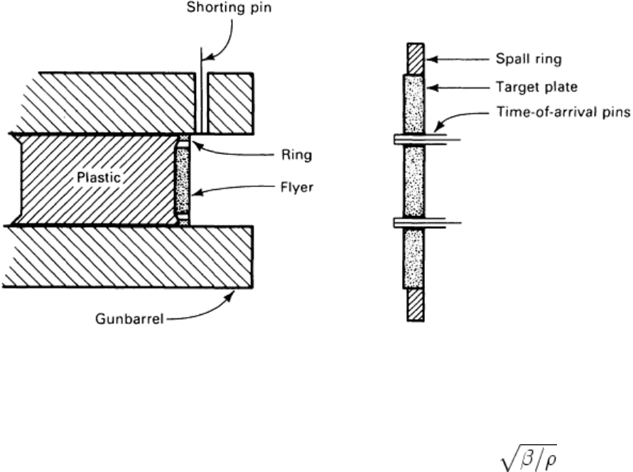
The flat plate impact test is performed by launching a flat flyer plate against a second stationary target plate.
Compressed gas guns, propellant guns, magnetic accelerators, and explosives have all been used to launch the
flyer plate (Ref 40). Extreme precision must be achieved to eliminate relative tilt at the instant of impact. A
typical experimental setup using a gas gun is shown in Fig. 8. The flyer plate is carried in the gas gun in a
plastic sabot. Velocity of the flyer is determined from the transit time between the shorting pin in the gun barrel
and time-of-arrival pins in the target. The target is supported by a spall ring that suppresses late-time radial
tensile waves.
Fig. 8 Schematic of gas-gun-launched flyer plate impact test setup
The stress waves along the axis normal to the impact plane are shown in Fig. 9. A flyer plate of thickness d,
moving left to right, strikes an initially stationary target of thickness T; the impact occurs at the origin, O, of the
(x, t) coordinates. Elastic-plastic behavior is assumed in Fig. 9. Elastic waves propagate at approximately c
EL
,
the longitudinal elastic sound speed. Plastic waves propagate at approximately where B is the bulk
modulus. The arrivals of the elastic and plastic waves at the target rear surface are denoted as E and P.
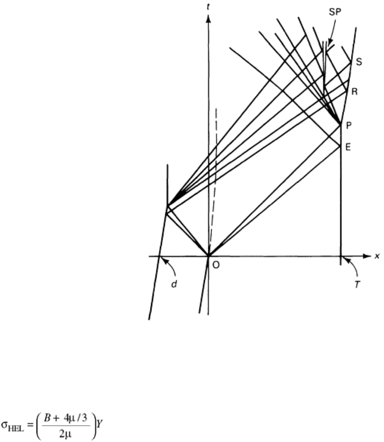
Fig. 9 Lagrangian diagram showing stress waves in flyer plate experiment
Propagation speeds are always relative to the material into which the wave is moving. Strain occurs only at the
wave fronts. The amplitude of the E wave in Fig. 9 is known as the Hugoniot elastic limit (HEL) and is simply
related to the uniaxial yield stress, Y, as:
(Eq 21)
where μ is the shear modulus. The final state of the shocked material is characterized by a stress and particle
velocity. The functional relationship between these two variables depends on the material and is known as the
Hugoniot. The state behind the P wave in Fig. 9 lies on the Hugoniot (see Ref 41 for a discussion of
Hugoniots). If the flyer and target plates are composed of the same material, the particle velocity behind the P
wave is one half the impact velocity.
Reference 42 discusses determination of particle velocity when the flyer and target are composed of different
materials. If the Hugoniot of the target is known, then the stress can be calculated from the particle velocity.
Hugoniots for most engineering metals can be found in Ref 43.
Compressive waves reflect from a free surface as tensile (rarefaction) waves, which begin to arrive at the target
rear surface at point R in Fig. 9. The tensile (rarefaction) waves may interact and cause spall failure. This
causes material separation in the target, which is indicated at point SP in Fig. 9. The sudden relaxation of tensile
stress generates a shock wave that arrives at the free surface at point S.
Spall is a form of tensile failure under an extremely high strain rate and a nearly spherical stress tensor. Spall
usually is characterized by the spall stress, σ
spall
, defined as the highest tensile stress that exists in the material
prior to rupture. When designing spall experiments, the flyer plate diameter, a, must be large enough so that the
phenomena of interest occur within a time a/2c
EL
after the impact.
Flat plate impact tests normally are used to measure σ
HEL
and spall strength. For example, consider the
characterization of a steel by this technique. The value of σ
HEL
for steel is usually between 5 and 15 kilobar
(kbar), a useful unit for analyzing shock experiments (1 kbar = 0.1 GPa). When density is expressed as g/cm
3
×
10 and velocity is given in km/s (or, equivalently, mm/μs), stress is given in kbar.
To measure the Hugoniot elastic limit, the impact velocity must be sufficient for the peak stress to exceed σ
HEL
.
Peak stress is given by:
σ = ρUv
(Eq 22)
where U is shock propagation speed and v is particle velocity. Peak particle velocity is half the impact velocity,
v
0
, for a symmetric impact. For steel-on-steel impacts, Eq 22 becomes approximately σ = 200 v
0
. For σ > σ
HEL
=
15 kbar, a v
0
greater than 75 m/s (245 ft/s) is required. This presents no problem when a gas gun is used.
Experiments with v
0
< 100 m/s (330 ft/s) are often difficult because of impact tilt, which becomes more critical
at low velocities. Also, impact velocity must not be so high that the velocity of the P wave (Fig. 9) exceeds c
EL
.
That limit for steels usually is greater than 1 km/s (0.6 mile/s). The limit for other materials can be found by
consulting the tables in Ref 43.
Given an appropriate impact velocity, to determine σ
HEL
one of the following measurements must be made. The
peak particle velocity behind the E wave can be measured. This can be accomplished at the free surface with
capacitor gages, sloping mirrors, or a velocity interferometer. The velocity behind the wave is half the free
surface velocity. The stress is related to the free surface velocity by Eq 22 with v = c
EL
.
Direct measurement of σ
HEL
can be obtained by embedded piezoresistive gages. Manganin and carbon gages
frequently are used for this purpose. This technique requires sectioning the target or using a backing plate and
correcting for partial transmission of the wave transmitted through the interface. Magnetic particle velocity
gages can be used for nonconducting targets, such as plastics and rocks, but they are not suitable for metals.
Spall stress can be determined by two methods. The simplest, in terms of analysis, interpretation, and
experimental technique, is to vary systematically the flyer plate thickness, d, and impact velocity, v
0
, to
determine the critical values at which rupture occurs. As the flyer plate thickness is increased, the duration of
the compressive and tensile load increases; the load duration is approximately 2d/c
EL
.
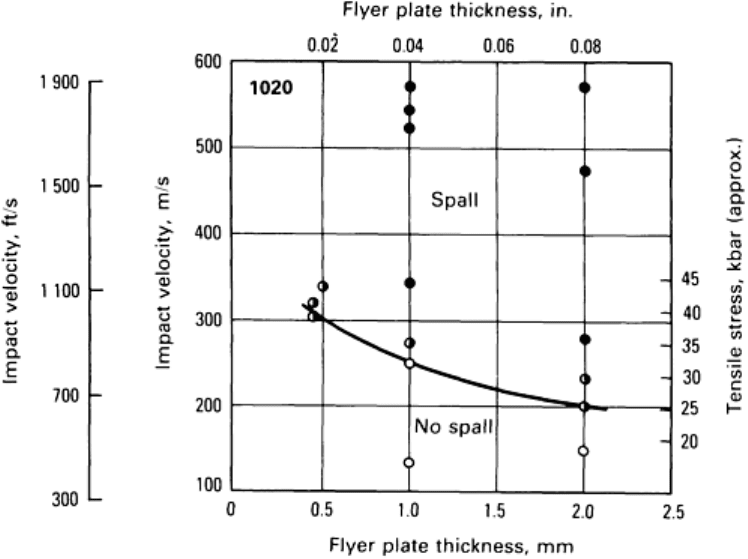
Eventually, for flyer plate thicknesses exceeding about 5 mm (0.2 in.), the spall stress reaches a load duration
limit. In many metals, the limiting spall strength is several times the value of σ
HEL
. Figure 10 illustrates typical
spall stress data for low-carbon steel. The data illustrate that for pulse durations longer than a few
microseconds, the greatest tensile stress that the material can sustain without rupture is 25 kbar.
Fig. 10 Spall data for low-carbon 1020 steel
Interpretation of experiments using thinner flyer plates is more complex because a computer code must be used
to calculate the stress history on the spall plane. Finite difference codes (Ref 41) or method of characteristics
codes (Ref 44) can be used. Finite difference codes are more accurate and more widely applicable than method
of characteristics codes, but the user must be specially trained in this subject.
Another approach to spall characterization is to initiate impact above the spall threshold and to deduce the
material behavior from the free surface velocity, Δv
s
, data. Figure 11 illustrates a typical free surface velocity
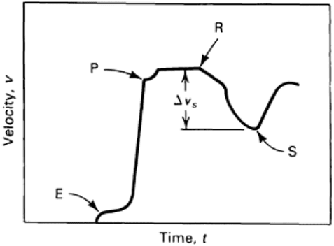
history with spalling. E, P, R, and S refer to the same arrivals as explained in text for Fig. 9. The spall stress is
given approximately by ρc
EL
Δv
s
/2. However, a more exact determination requires code analysis.
Fig. 11 Free surface velocity data when spall occurs
Split-Hopkinson Bar in Tension
The principles of the split-Hopkinson bar in tension are similar to those in compression, as discussed in the
article “Classic Split-Hopkinson Pressure Bar Testing” in this Volume. The primary differences are the
methods of generating a tensile loading pulse, specimen geometry, and the method of attaching the specimen to
the two bars (incident and transmitter).
Basically, three types of tension split-Hopkinson bars have been developed. The first (Ref 45) involves the use
of compressive pulses in the input and transmitter bars, as in the compressive test. The input bar is solid, while
the transmitter or output bar is a hollow tube of the same cross-sectional area as the input bar. The specimen is a
complex “top-hat” type of geometry, as shown in Fig. 12. The specimen actually is comprised of four parallel
tensile bars of equal cross-sectional area. Although specimen machining is somewhat complex, the test is
conducted in the same manner as compressive testing.
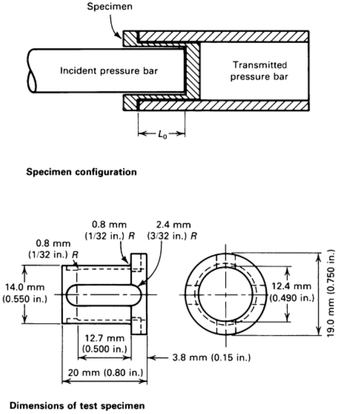
Fig. 12 Details of the split-Hopkinson tension specimen. Source: Ref 45
The second type of tension split-Hopkinson bar test involves the use of a smaller standard type of threaded
tension specimen and generation of a tensile pulse directly on the end of the loading or input bar (Ref 46, 47).
This can be accomplished in several ways, as shown in Fig. 13. In Fig. 13(a), a mass is impacted directly on an
anvil attached to the end of the input bar. In Fig. 13(b), an anvil is loaded by a compressive wave transmitted
through another loading bar that is a hollow tube. The compressive pulse in the loading tube is generated by the
same techniques as the compression split-Hopkinson bar. In Fig. 13(c), a pulse is generated by the detonation of
an explosive against the anvil. In Fig. 13(a) and (c), it is difficult to generate a pulse of constant amplitude,
while in Fig. 13(b) a long time duration is accomplished in the same manner as in compressive testing.
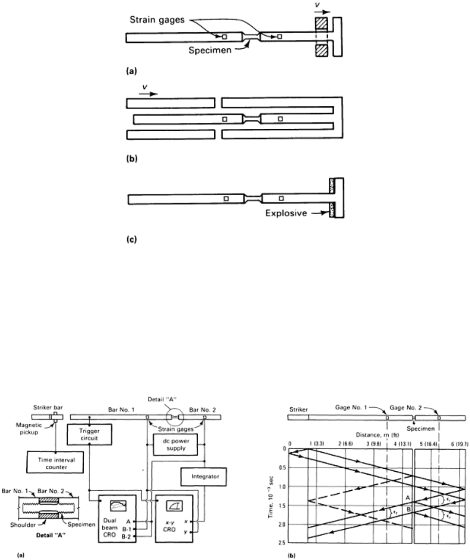
Fig. 13 Schematic of three types of split-Hopkinson tension-loading techniques
The third type of tension test also uses a threaded specimen but uses the reflection of a compression pulse at a
free end and a collar to protect the specimen from initial precompression (Ref 48). Figure 14(a) illustrates an
experimental setup. Figure 14(b) is a Lagrangian x-t diagram, which illustrates the details of wave propagation
in the bars and the experimental procedures. When the striker bar is accelerated against bar No. 1, the impact
generates a compression pulse, the amplitude of which depends on the striker velocity and the length of which
is twice the elastic wave transit time in the striker bar. The pulse travels down the bar until it reaches the
specimen. The threaded tensile specimen is attached to the two pressure bars, as shown in detail “A” of Fig.
14(a).
Fig. 14 Split-Hopkinson bar test using threaded tension specimen. (a) Schematic of tensile loading
apparatus. Source: Ref 48. (b) Lagrangian diagram for tensile loading apparatus. CRO, cathode ray
oscilloscope
After the specimen has been screwed into the bars, a split shoulder or collar is placed over the specimen, and it
is screwed in until the pressure bars fit tightly against the shoulder. The shoulder is made of the same material
as the pressure bars, has the same outer diameter, and has an inner diameter that just clears the specimen. The
ratio of the cross-sectional area of the shoulder to that of the pressure bars is typically 3:4, while the ratio of the
area of the shoulder to the net cross-sectional area of the specimen is typically 12:1.
The compression pulse travels through the composite cross section of the shoulder and specimen in an
essentially undispersed manner. Tightening of the specimen by twisting the pressure bars, the relatively loose
fit of the threaded joint of the specimen into the bars, and the large area ratio of the shoulder to the specimen
ensure that no compression beyond the elastic limit is transmitted to the specimen.
Ideally, the entire compression pulse passes through the supporting shoulder as if the specimen were not
present, although in practice it is difficult to prevent prestraining of the specimen. The compression pulse
continues to propagate until it reaches the free end of bar No. 2. There it reflects and propagates back as a
tensile pulse, ε
i
, and passes gage No. 2. Upon reaching the specimen at point A as shown in Fig. 14(b), the
tensile pulse is partially transmitted through the specimen, ε
t
, and partially reflected back into bar No. 2, ε
r
.
Note that the shoulder, which carried the entire compressive pulse around the specimen, is unable to support
any tensile loads because it is not fastened to the bars.
Tight fitting of the shoulder against the bars is critical in transmitting the compression pulse down the bars
without significant wave dispersion. Similarly, the tight fit of the threaded tensile specimen against the bars is
essential to achieve smooth and rapid loading of the specimen as the tensile pulse arrives. Failure to remove all
“play” from the threaded joint results in uneven loading of the specimen and spurious wave reflections.
Analysis of the tensile split-Hopkinson bar test is almost identical to that of the compression test. The major
difference is the actual or effective gage length of the specimen. Contrary to the compression test, in which a
right circular cylinder is used, the tensile test uses a cylindrical specimen with an attached shoulder and
additional gripping, such as threads. Because the split-Hopkinson bar test can only provide data on the relative
displacement between the ends of the incident and transmitter bars, an effective gage length generally must be
used. This is equivalent to determining strain in a tensile test through crosshead displacement measurement.
The use of strain gages on test samples to determine an effective gage length is strongly recommended. This
calibration is accomplished easily at low strain rates, preferably in a conventional test machine in which the
crosshead displacement is monitored separately.
As with any uniaxial tensile test, once localized necking occurs, it is no longer possible to simply convert load-
displacement data to stress-strain data. The range of application of the Hopkinson bar test can be extended by
high-speed photography of necking specimens. An analysis that allows estimation of effective stress and strain
from the profile of the necking specimen is described in Ref 49. Photographs can be made with a suitable high-
speed camera system through windows provided in the collar. The major technical difficulty is the precise
synchronization of the exposures with the Hopkinson bar record (Ref 50).
References cited in this section
32. T. Nicholas and S.J Bless, High Strain Rate Tension Testing, Mechanical Testing, Vol 8, ASM
Handbook, ASM International, 1985, p 208–214
33. F.I. Niordson, A Unit for Testing Materials at High Strain Rates, Exp. Mech., Vol 5, 1965, p 29–32
34. C.R. Hoggatt and R.F. Recht, Stress-Strain Data Obtained at High Strain Rates Using an Expanding
Ring, Exp. Mech., Vol 9, 1969, p 441–448
35. D.E. Grady and D.A. Benson, Fragmentation of Metal Rings by Electromagnetic Loading, Exp. Mech.,
Vol 28, 1983, p 393–400
36. A.M. Rajendran and I.M. Fyfe, Inertia Effects on the Ductile Failure of Thin Rings, J. Appl. Mech.
(Trans. ASME), Vol 104, 1982, p 31–36
37. L.M. Barker and R.E. Hollenback, Laser Interferometer for Measuring High Velocities of Any
Reflecting Surface, J. Appl. Phys., Vol 43, 1972, p 4669–4674
38. R.H. Warnes, T.A. Duffey, R.R. Karpp, and A.E. Carden, An Improved Technique for Determining
Dynamic Material Properties Using the Expanding Ring, Shock Waves and High-Strain-Rate
Phenomena in Metals, M.A. Meyers and L.E. Murr, Ed., Plenum Press, 1981
39. D. Bauer and S.J. Bless, Strain Rate Effects on Ultimate Strain of Copper, Shock Waves in Condensed
Matter, North Holland, Amsterdam, 1983

40. G.R. Fowles, Experimental Technique and Instrumentation, Dynamic Response of Materials to Intense
Impulse Loading, P.C. Chou and A.K. Hopkins, Ed., Air Force Materials Laboratory, Wright-Patterson
Air Force Base, 1973
41. J.A. Zukas, T. Nicholas, H.F. Swift, L.B. Greszczuk, and D.R. Curran, Impact Dynamics, John Wiley &
Sons, New York, 1982, p 452
42. R.G. McQueen, S.P. Marsh, J.W. Taylor, J.N. Fritz, and W.J. Carter, The Equation of State of Solids
from Shock Wave Studies, High Velocity Impact Phenomena, R. Kinslow, Ed., Academic Press, 1970
43. S.P. Marsh, LASL Shock Hugoniot Data, University of California Press, 1980
44. L.M. Barker and E.G. Young, “SWAP-9: An Improved Stress Wave Analyzing Program,” Sandia
National Laboratories Report SLA-74-0009, Albuquerque, NM, 1974
45. U.S. Lindholm and L.M. Yeakley, High Strain Rate Testing: Tension and Compression, Exp. Mech.,
Vol 8, 1968, p 1–9
46. J. Harding, E.D. Wood, and J.D. Campbell, Tensile Testing of Material at Impact Rates of Strain, J.
Mech. Eng. Sci., Vol 2, 1960, p 88–96
47. C. Albertini and M. Montagnani, Testing Techniques Based on the Split Hopkinson Bar, Mechanical
Properties at High Rates of Strain, J. Harding, Ed., Institute of Physics, London, 1974
48. T. Nicholas, Tensile Testing of Materials at High Rates of Strain, Exp. Mech., Vol 21, 1980, p 177–185
49. P.W. Bridgeman, Chapter 1, Studies in Large Plastic Flow and Fracture, 1st ed., McGraw-Hill, 1952
50. L.A. Cross, S.J. Bless, A.M. Ranjendran, E.A. Strader, and D.S. Dawicke, New Technique to
Investigate Necking in a Tensile Hopkinson Bar, Exp. Mech., Vol 24 (No. 3), 1984, p 184–186
High Strain Rate Tension and Compression Tests
Rotating Wheel
Another method for tension testing at high strain rates consists of a rotating wheel with claws or noses that
quickly stroke a yoke containing test pieces. An early test machine was developed by Mann in 1936 (Ref 51),
and in 1944 Fehr et al. (Ref 52) reached strain rates of nearly 10
3
s
-1
with some bearable ringing. In the 1960s,
Schopper produced and sold about 100 “rotating wheel machines,” which also had a 200 kg (440 lb) wheel with
a releasable claw and a specimen within a yoke fixed in front of the wheel (Fig. 15). By careful adjustments,
velocities of about 40 m/s (130 ft/s) were reached without any bending moments. However, the overall
frequency response of the fixture (despite the 50 kHz quartz transducer for force-time recording) was only 2.5
kHz, which is too low for high-rate testing.
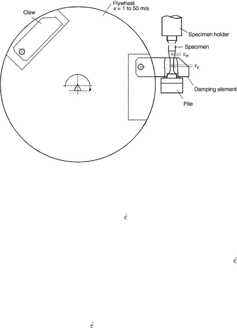
Fig. 15 Principle of high-rate tensile testing with flywheel setup
The essential improvement has been to introduce load-measuring gages as close to the gage length as possible.
This is realized by measuring elastic strains and converting to stresses by the elastic modulus. To assure low
barriers for reflections of stress wave propagation, the strain gages for load measurement are positioned at
cones of 8° on the smallest possible diameter. With this technique, stress-strain records are possible up to
velocities of 30 m/s, which corresponds to strain rates of = 2500 s
-1
with a gage length of 10.5 mm (0.41 in.)
and a diameter of 3.5 mm (0.14 in.) (L/D = 3). Even with high strain hardening and highly deformable
materials, there is practically no influence of the tested materials on the history of velocity or strain rate like in
a Hopkinson bar setup because the energy content of the rotating wheel exceeds the fracture energy of the
specimen more than 10 times (for striking velocities v > 10 m/s, or 33 ft/s).
A similar setup, but based on a moving mass of a few kilograms guided along straight bars, has also been
developed by Stelly and Dormeval at CEA, France with good results (Ref 53). Higher strain rates of = 10
4
s
-1
,
for example, can be reached with short gage length. To provide easy strain recording for the complete loading
up to fracture, electro-optical cameras or noncontact laser interferometers can be used. The advantage of this
instrumentation is that the strain is measured, not calculated under certain assumptions.
In order to avoid more reflections of the stress wave from the upper end of the specimen, the length beside the
gage length is extended to 2s > v
c
· t (where s is the rod length between gage length and fixture, v
c
is the sound
velocity, and t is the time to fracture at the used striking velocity). In the case of short lengths, a wave
transmitter bar is connected to the specimen. This procedure requires the evaluation of impedance transfer
between the sample and bar. Figure 16 shows stress-time diagrams of screwed, brazed, and welded joints tested
under high strain rate conditions at about = 1000 s
-1
. These results reveal that screwing and brazing are
insufficient methods to obtain stress-time diagrams of good quality. Therefore, in this test setup welded joints
are most suitable to perform tensile tests at high and very high strain rates.
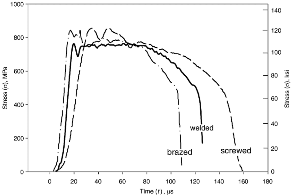
Fig. 16 Influence of joining method on stress-time curves for high strain rate tension test specimens
This procedure was successfully applied for high-rate, high-temperature tests (Fig. 17). Notice the occurrence
of the upper and lower yielding and the following nearly undisturbed stress-time records. The wave transmitter
bar was used for a stress measurement because the strain gages at the gage length were unsuitable at test
temperature. Temperatures up to 600 °C (1100 °F) are reached with heated air; higher temperatures should be
possible using small infrared ovens (Ref 54, 55) or induction heating.
