ASM Metals HandBook Vol. 8 - Mechanical Testing and Evaluation
Подождите немного. Документ загружается.

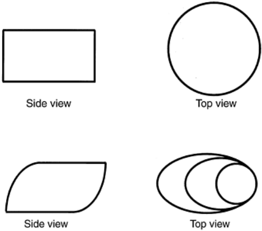
Fig. 4 Schematics of an ideally tested specimen
Fig. 5 Schematics of a tilted (sheared) tested specimen
Temperature Measurement. Temperature measurement using a thermocouple that just touches the specimen is
not accurate until the specimen is soaked at the set testing temperature for a long time. To accurately measure
the temperature of the specimen, thermocouples can be either welded to the specimen or inserted into a small
hole drilled into the specimen. Hole drilling is not recommended for workability testing because the hole may
induce premature cracking. To determine the uniformity of temperature within the specimen, three
thermocouples may be used to measure the top, bottom, and center temperatures of a dummy specimen as a
function of time. If the temperatures are identical, only one thermocouple is necessary during testing. If it takes
some time for the entire specimen to reach the set temperature, this procedure can also be used to determine the
necessary soaking time. To obtain the microstructure right before the compression testing begins, a specimen
soaked at the testing temperature for the specified time should be quenched and examined. Some other detailed
precautions for temperature measurement are specified in Ref 14.
It is essential that the platens be at the same temperature as the specimen. Temperature difference between the
platens and the specimen results in a deformation gradient and, therefore, barreling of the deformed specimen
(Ref 19).
Lubrication. When the specimen is compressed homogeneously, as shown in the ideal case (Fig. 4), the
resulting stress calculations are accurate. For most tests, deformed specimens look like the one in Fig. 3 due to
friction, even with lubrication. For testing at room temperature, TFE-fluorocarbon sheet and molybdenum
disulfide can be used (Ref 13, 20). For testing at elevated temperatures, water-base graphite, graphite sheet,
boron-nitride solution, glass-base lubricant, and molybdenum disulfide may be used (Ref 8, 21).
To retain lubricant on the ends of the specimens, various end designs have been developed (Ref 7, 21, and 22).
One such design is shown in Fig. 6. The procedure for applying lubricant solutions on the ends of the
specimens is also very important. The lubricant needs to be applied twice on each end. The second application
can only be made after the first application dries.
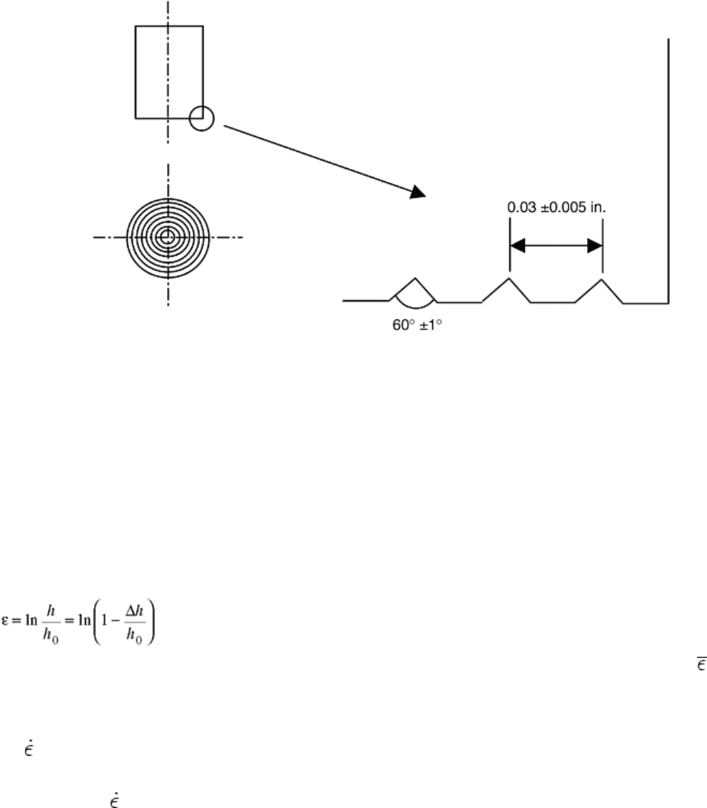
Fig. 6 A typical groove design for the ends of compression test specimens
Machine Stiffness. Because the testing train consists of a number of components, as shown in Fig. 1, the
stiffness of the system needs to be quantified. The easiest way to quantify is to bring the top and bottom platens
together and record the displacement at a number of load levels. This procedure needs to be performed at each
testing temperature. For high-strain compression tests, for instance, 60 to 80%, it is not possible to attach an
extensometer to the specimen. The displacement data must be subtracted by the intrinsic displacement that
resulted from the system. The subtraction can be incorporated into a data acquisition program.
Machine Control. The testing machine should be controlled to generate constant strain rates during testing. To
do so, the motion of the crosshead must follow exponential curves. The true strain is expressed as a function of
specimen height as follows:
(Eq 9)
where ε is true strain (in the case of compression or tension, if the deformation is homogeneous, ε = ), and h
0
and h are the initial and instantaneous height of the specimen, respectively. Δh = h
0
- h is the distance the
crosshead has traveled since the compression test commenced.
For a constant strain-rate test, the instantaneous strain is simply the product of strain rate and time:
ε = t
(Eq 10)
Combining Eq 9 and 10 yields:
Δh = h
0
[1 - exp( t)]
(Eq 11)
For hydraulic machines, the distance of crosshead travel is controlled by the voltage input as a function of time.
For a mechanical machine, the crosshead is controlled by the motor speed. In general, Eq 11 is the governing
equation for machine control for constant strain-rate compression tests. The equation for tension tests can be
derived similarly with the exception of Δh = h - h
0
. Software to control the machine for constant strain-rate tests
has recently become commercially available (Ref 23).
Data Reduction and Temperature Correction. Load and stroke (displacement) data are acquired from testing. To
reduce the data into true stress and true strain, deformation is assumed homogeneous. True strain is calculated
using Eq 9. Of course, the correction for the elastic deflection of the machine needs to be considered (Ref 24).
True stress is simply the load divided by instantaneous cross-sectional area, which can be calculated by
assuming a constant volume of the specimen.
Deformation heating occurs inevitably during testing, especially at high strain rates. Because isothermal stress-
strain curves are desired for analysis, correction for deformation heating is necessary. The commonly used
equation for calculating temperature rise during deformation is (Ref 25):
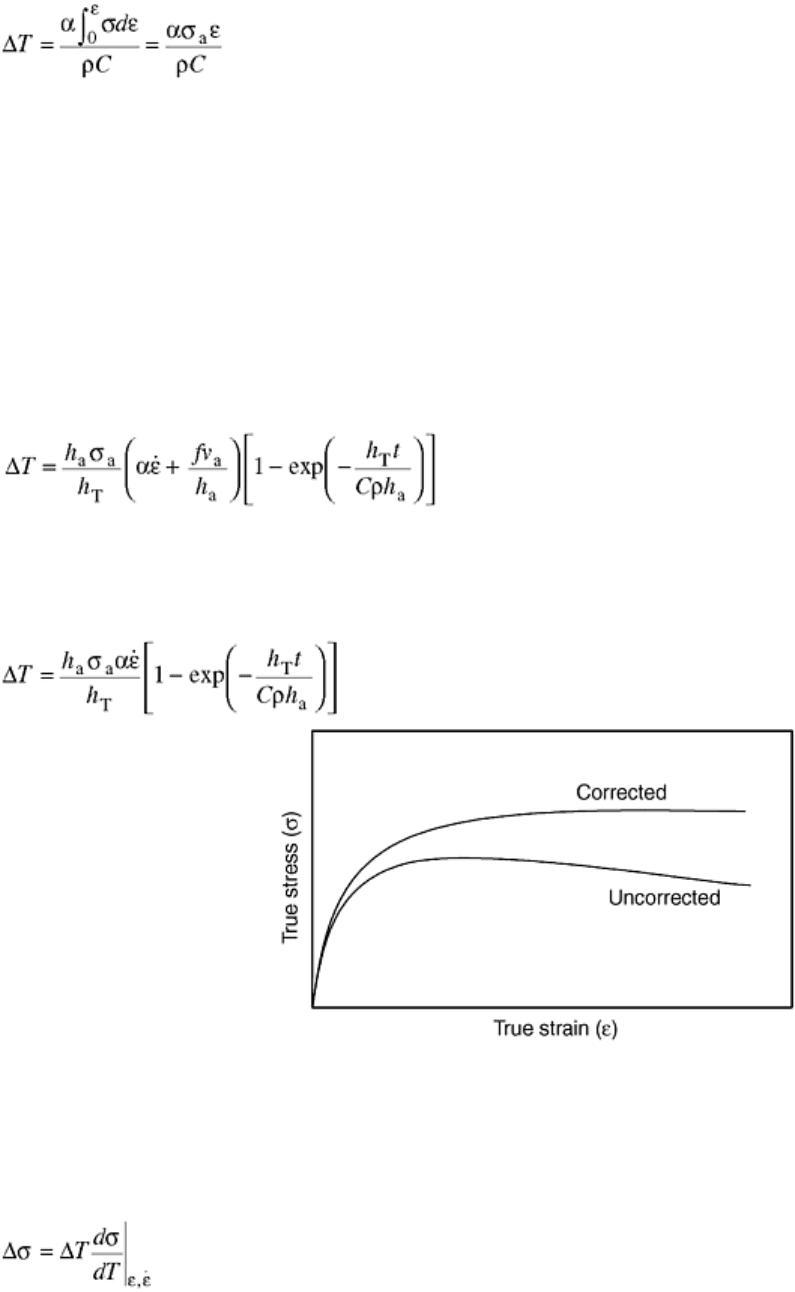
(Eq 12)
where σ
a
is the average stress value over the strain range of testing, ρ is density, C is mass heat capacity of the
specimen, and α is the fraction of deformation energy transformed into heat. Usually α is equal to 0.98.
As shown in Eq 12, the temperature rises continuously as the test continues. A typical stress-strain curve
obtained after testing and deformation heating correction would look like the curves in Fig. 7. Deformation
heating is most severe at low temperatures and high strain rates, where the stress level is high. At high strain
rates, higher than, for instance, 1 s
-1
, there is not much time for heat to dissipate, and the specimen is basically
under adiabatic conditions. Equation 12 applies under these conditions. In contrast, when strain rates are very
slow, such as 10
-3
s
-1
, heat generated from deformation is transferred to tooling and the environment, and
deformation heating is negligible. However, Eq 12 does not reflect the effect of strain rate, and still provides a
finite temperature increase. In addition, the equation does not apply at even intermediate strain rates. To solve
these problems, Zhao (Ref 26) developed an equation for calculating temperature increase due to deformation
heating at all strain rates, which also includes the heat generated by friction at the platen/specimen interface:
(Eq 13)
where h
a
is the average height of the specimen, h
T
is the heat-transfer coefficient between the platen and the
specimen, f is the friction coefficient between the platen and the specimen, t is time, and ν
a
is the average
velocity at the platen/specimen interface. If lubrication is excellent and friction is negligible, Eq 13 can be
reduced to:
(Eq 14)
Fig. 7 A schematic of stress-strain curves before and after correction for deformation heating
The purpose of determining temperature increase is to obtain isothermal stress-strain curves. Strength loss of
the specimen due to deformation heating can be expressed in terms of the derivative of stress by temperature
(Ref 27):
(Eq 15)
The way to determine the derivative is to plot stress data at constant strain and strain rate, and at corrected
temperatures (T = T
test
- ΔT), as shown in Fig. 8. The derivative is usually a function of temperature.
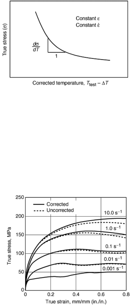
Fig. 8 A schematic showing determination of derivative of stress in terms of temperature
The step-by-step procedure for reducing load-stroke data is:
1. Convert load-stroke data to true stress-versus-true strain data, including correction for machine elastic
deflection.
2. Calculate ΔT for every data point using Eq 13 or 14.
3. Plot true stress-versus-corrected temperature at each strain rate and at a number of constant strains.
4. Obtain the slope of the plotted curves in step 3 using dσ/dT.
5. Calculate the stress increase when temperature is corrected to the nominal testing temperature.
6. Generate isothermal stress-strain curves by adding the stress increase to the true stress obtained in the
first step.
Figure 9 shows both uncorrected and corrected stress-strain curves for HY-100 steel at 1000 °C (1830 °F) and
at various strain rates.
Fig. 9 Stress-strain curves before and after temperature corrections for HY-100 steel at 1000 °C (1830
°F) and various strain rates. Source: Ref 8
Tension Test
When compression-testing equipment is not available, or the deformation process experiences more tension
than compression, tensile testing can be used to obtain stress-strain curves. Tensile testing can be especially
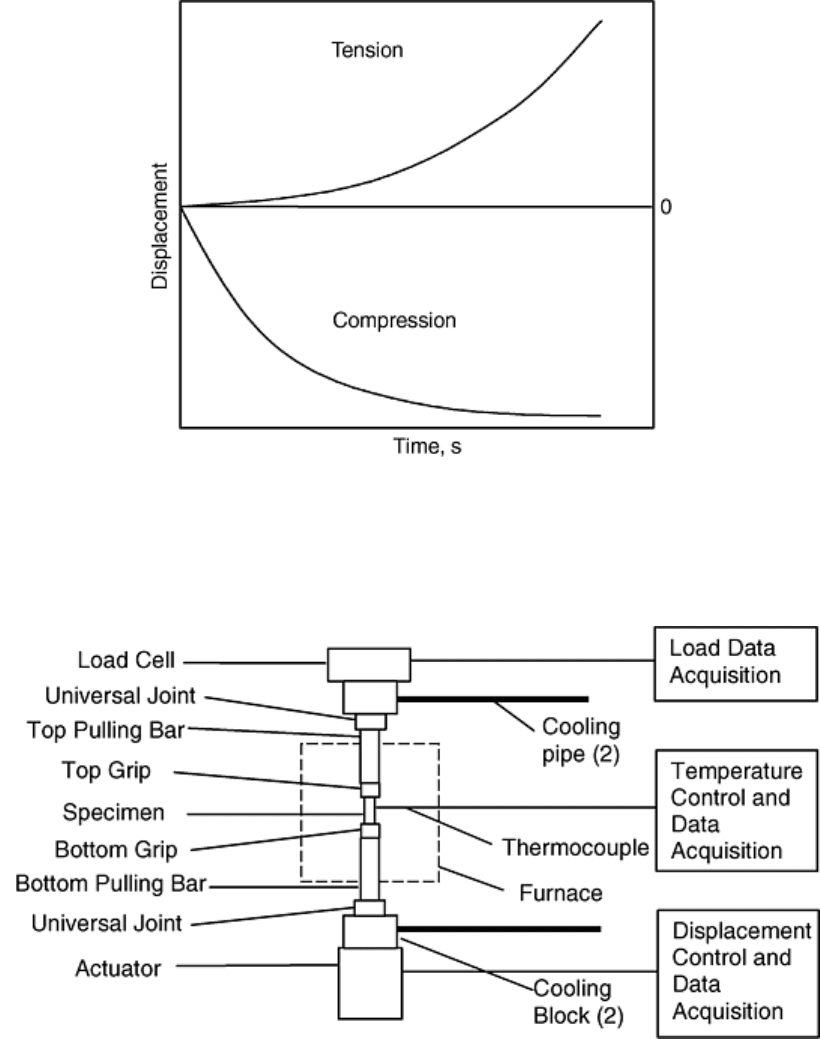
useful for sheet-metal forming applications. Constant strain-rate tensile tests should follow an exponential
curve, as shown in Fig. 10.
Fig. 10 Displacement as a function of time for tension and compression tests at constant strain rate
The setup of high-temperature tensile-testing equipment is similar to compression testing. The difference is that
tensile testing does not need anvils and platens. Instead, it uses pulling bars and grips. Figure 11 shows a typical
setup of high-temperature tensile loading train.
Fig. 11 Loading train for high-temperature tensile testing
The grips can be either of the screw type or the split-ring type; both are commercially available. Split-ring grips
provide for a quick removal of the specimen if quenching immediately after testing is desirable and has to be
performed outside the furnace.
Universal joints are necessary to align the loading train. In any case, the maximum bending strain should not
exceed 10% of the axial strain. One way to check the bending strain is to use strain gages on a specimen at the
middle of the gage length. If the maximum (or minimum) bending strain is within the limit at room
temperature, the alignment should be fine at elevated temperatures. Care must be taken not to affect the
alignment of the loading train with the furnace and its accessories. The alignment needs to be tested
periodically.
Because tensile specimens usually have longer gage lengths than compression specimens, more than one
thermocouple may be needed to monitor the temperature of the gage length. Thermocouples should very closely
contact the reduced section. Shielding the thermocouple is necessary unless the difference in indicated
temperature from an unshielded bead and a bead inserted in a hole in the specimen has been shown to be less
than one half the variation listed here (Ref 16):
Up to and including 1000 °C (1800 °F)
±3 °C (5 °F)
Above 1000 °C (1800 °F) ±6 °C (10 °F)
Thermocouples need to be calibrated as specified in Ref 16. Thermocouple wire exposed to a hot zone should
be cut off after each test, and a new bead should be formed. During the entire test, temperature variation should
not exceed the ranges indicated in the previous table for the entire gage length.
One of the advantages of a tensile test compared to a compression test is that the tensile test does not have a
friction effect, and an extensometer can be used to measure true strain up to the maximum loading. The true
stress would have to be corrected due to the reduction of cross-sectional area. Stress-strain data may not be
useful beyond the maximum load point due to necking. Attachment of the extensometer should be carried out
very carefully because it may affect alignment (Ref 28). Attaching extensometers on opposite sides and
averaging the readings can reduce the error. When feasible, extensometers should be attached directly to the
reduced section (Ref 16).
One important parameter that can be determined from tensile tests is the strain-hardening exponent, n, which is
important for both bulk and sheet-metal forming. The procedure used to determine n-values is quite simple and
is explained well in Ref 29.
Young's modulus can also be determined by tensile tests with accurate extensometers. Temperature control
during the test is very important. The average temperature over the specimen gage length should not deviate
from the indicated nominal test temperature by more than ±1.5 °C (2.5 °F) for test temperatures up to and
including 900 °C (1650 °F), and ±3 °C (5.5 °F) for above 900 °C (1650 °F) (Ref 30). The loading rate should
also be slow in order to avoid the thermal effect of adiabatic expansion or contraction. However, the test speed
should not be so slow that creep effects are not negligible (Ref 30).
Data Reduction for Workability
Workability is an important issue in deformation modeling. For bulk workability, Kuhn developed the testing
technique described in Ref 11. The workability constant C for a particular material at certain testing
temperature and strain rate can be determined by a simple plane-strain bending test. The constant C is related to
the constant C′ in Eq 7 and 8 as follows:
C = 0.75C′
(Eq 16)
It also relates to the constant C
2
in Eq 6 (Ref 31):
(Eq 17)
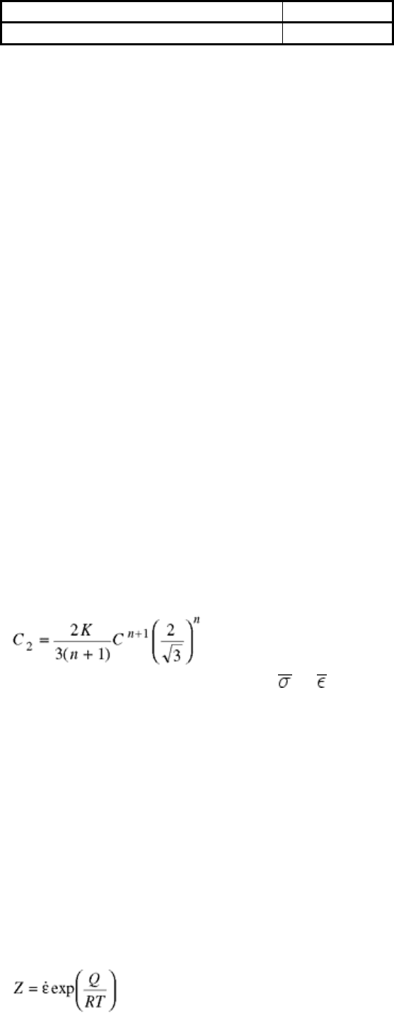
assuming that the constitutive equation = K
n
applies.
Fitting Testing Data to Constitutive Models
If one uses the tabular input form for modeling, the interpolation of data is left to the finite element modeling
(FEM) software after stress-strain data have been obtained. Care must be taken to ensure that the temperature
and strain-rate ranges in the data cover every possible case in the simulation for convergence.
If a constitutive model is being used, data needs to be fit to the equation. Equation 2 is not difficult to fit.
However, Eq 3 has four constants: A, α ,n′, and Q, and the procedure to fit it is somewhat complex. There are
many ways to fit the data; some may lead to significant errors. A description of a general procedure to
determine the constants follows.
Equation 3 can also be written as:
Z = A[sinh (ασ)]
n′
(Eq 18)
where Z is the Zener-Hollomon parameter, defined as:
(Eq 19)
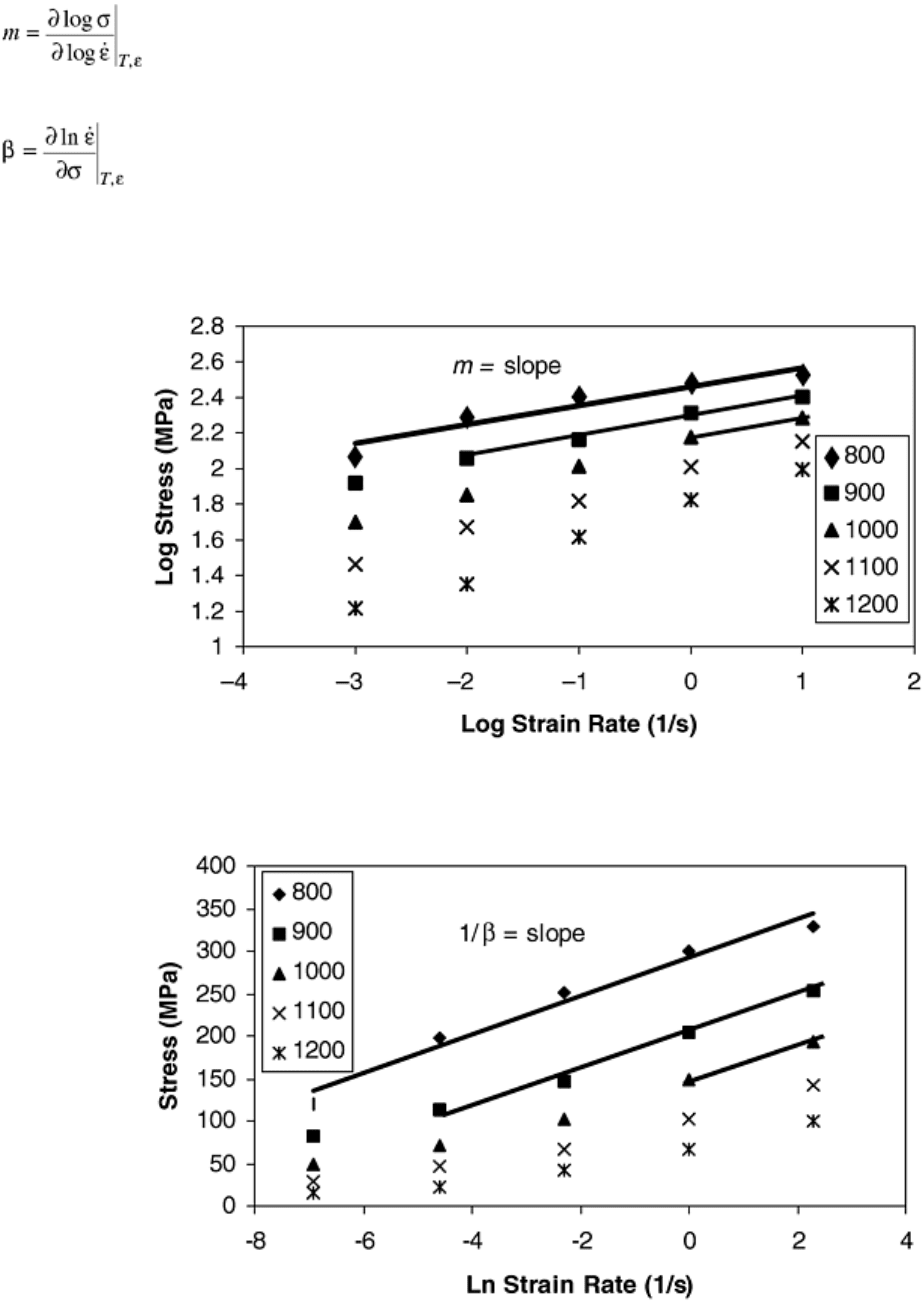
To determine parameter α, we need to determine the strain-rate sensitivity, m, and another material parameter,
β. At high stresses, the following relationship holds:
α = mβ
(Eq 20)
When n′ is replaced approximately by 1/m, the following equations result:
(Eq 21)
and
(Eq 22)
Steady-state stresses are plotted for each temperature-versus-strain rate example on a log-log scale, as shown in
Fig. 12. The slope of the straight lines is the strain-rate sensitivity, m. At high stresses, the lines are parallel.
The parameter β can be determined from the slope of stress versus the natural log of strain rate, as shown in
Fig. 13. From the m and β values, α can be determined using Eq 20.
Fig. 12 Steady-state stresses versus strain rate at different temperatures ( °C) on a log-log scale for HY-
100 steel
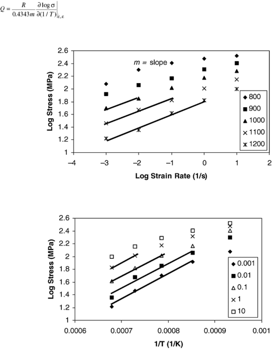
Fig. 13 Steady-state stresses versus natural log of strain rate at different temperatures ( °C) for HY-100
steel
Equation 4 yields:
(Eq 23)
Again, n′ is approximately replaced by 1/m. However, this time the m value is determined from the low stresses,
as shown in Fig. 14. The apparent activation energy, Q, can be determined by plotting log stress versus 1/T at
low stresses, as shown in Fig. 15. In Eq 23, R is the gas constant.
Fig. 14 Steady-state stresses versus strain rate at different temperatures ( °C) on a log-log scale for HY-
100 steel
Fig. 15 Log stress versus 1/T at different strain rates (in 1/s) for HY-100 steel
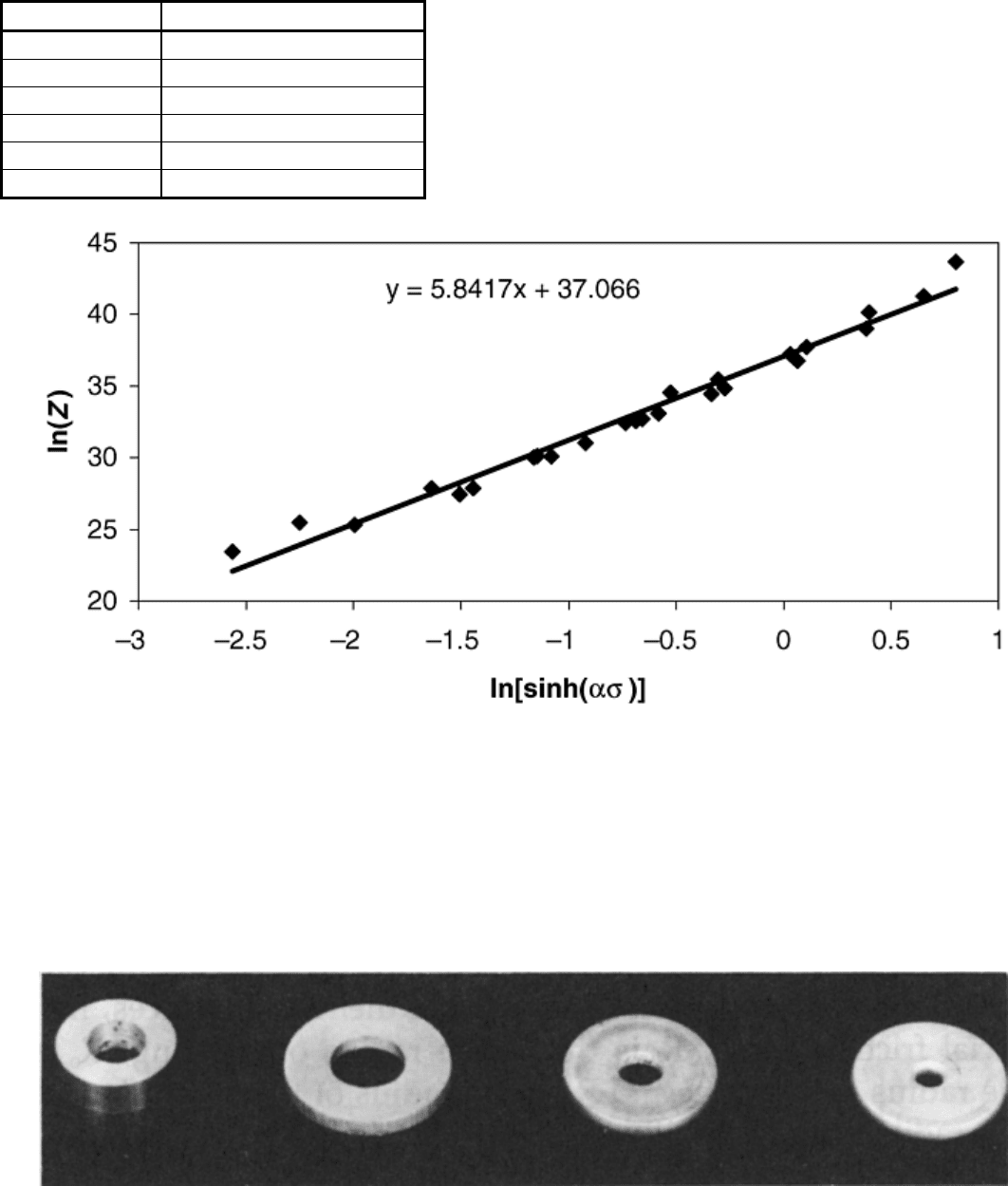
After obtaining the values of α and Q, the natural log of Z (Zener-Hollomon parameter) is plotted versus the
natural log of sinh(ασ) to determine the values of n′ and A. If the deformation behavior is governed by Eq 18,
the plot can be well fit by a linear equation, as shown in Fig. 16. The slope would be equal to n′, and the
intercept would be ln A. The final results for HY-100 steel are shown here:
m at high σ
0.1059
m at low σ
0.2089
β
0.0441
α, MPa
-1
(ksi
-1
)
4.671 × 10
-3
(6.775 × 10
-4
)
Q, kJ/mol
368.67
n′
5.8417
A, s
-1
1.2519 × 10
16
See Eq 3
Fig. 16 Plot of In(Z) versus In[sinh(ασ)] to determine the values of n′ and A
Testing for the Friction Coefficient
For bulk forming, the friction coefficient can be measured by a ring compression test (Ref 32). The principle of
this test is that when a ring is compressed, the inner diameter of the ring either increases or decreases depending
on the friction condition at the ring/platen interface. As shown in Fig. 17, measurements of the inside diameters
of the ring specimens provide a sensitive means to determine the friction coefficient because the inside diameter
increases if the friction is low and decreases if the friction is high.
Fig. 17 Variation in shape of ring specimen under different friction conditions. (a) Undeformed. (b) Low
friction. (c) Medium friction. (d) High friction. 50% deformation for (b), (c), and (d). Source: Ref 32
The specimen, as shown in Fig. 18, is usually made with a specific geometry ratio. The ratio of outer diameter
to inner diameter to thickness (D
o
:D
i
:T) is 6:3:x, where x can be 0.5, 1, or 2. The analysis of this test is based on
homogeneous deformation. To avoid error introduced by bulging or for high friction, the x-value 0.5 should be
used. For medium friction, the x-value 1 should be used, and for low friction, the x-value 2 should be used.
Analytical treatment that takes into account bulging for the specimens 6:3:2 was provided by DePierre, Gurney,
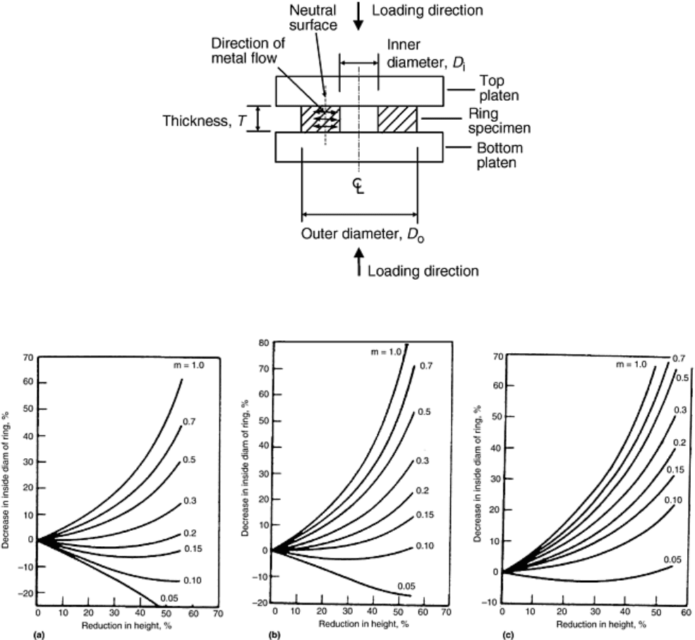
and Male (Ref 33). Before testing, lubricant is applied to the surface of the ring specimen. The testing is
conducted the same way as compression testing at a certain temperature and strain rate. After a certain amount
of deformation (reflecting the forming operation reduction), the test is ended, and the inner diameter of the
tested ring specimen is measured. The measured value and percent reduction are then compared to a set of
calibration curves (Fig. 19) to determine the friction coefficient (Ref 4, 32, 34, and 35).
Fig. 18 Schematic of ring compression test. Revised from Ref 4
Fig. 19 Theoretical calibration curves for ring compression test. The ratio is for outside diameter:inside
diameter:thickness. (a) 6:3:2 ratio. (b) 6:3:1 ratio. (c) 6:3:0.5 ratio. Source: Ref 4
Testing for the Heat-Transfer Coefficient
Deformation processing often involves heat transfer. One of the difficulties in modeling is determining the
input value of the heat-transfer coefficient. The most commonly used method of determining the heat-transfer
coefficient is the inverse method. In this method, the temperatures of the workpiece and tooling are measured at
different locations as a function of time. Subsequently, the process is modeled with trial values of the heat-
transfer coefficient to match the temperature measured in the experiments. The trial-and-error method for
determining the heat-transfer coefficient can be programmed to loop the simulations until an optimum value of
the coefficient is determined.
Chen, Samarasekera, and Hawbolt (Ref 36) performed such work on the hot rolling of steels. Figure 20 shows
the workpiece geometry and the position of thermal couples. Three thermocouples were used in this case to
measure the temperatures at different locations. Figure 21 shows how the experimental equipment was
