ASM Metals HandBook Vol. 8 - Mechanical Testing and Evaluation
Подождите немного. Документ загружается.

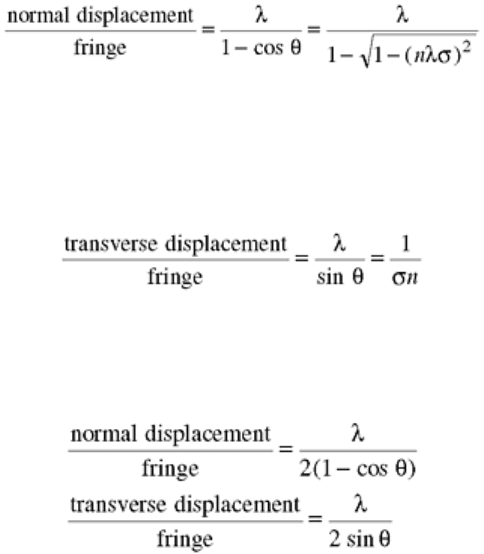
Fig. 4 Optical layout of a variable sensitivity displacement interferometer (VSDI) system. The Θ
±
system
is obtained by combining a normally reflected beam and a diffracted beam at an angle Θ
±
. In this figure,
mirrors M0-M5 and beam splitters BS1-BS3 are used to obtain the VSDI systems. The lens with focal
length F is used to focus the beam at the grating plane in the anvil back surface. Source: Ref 52
For purely normal motion (desensitized normal displacement interferometer, DNDI):
where σ = 1/d represents the frequency of a diffraction grating with pitch d. The fringe constant varies from
infinity at θ = 0° to λ (mm/fringe) at θ = 90°. Therefore, a VSDI is obtained that is particularly well suited for
normal plate impact experiments with particle velocities in excess of 100 m/s (330 ft/s). Clearly, the selection
of the appropriate angle θ should be based on deductive knowledge of the frequency range that will be spanned.
For purely in-plane motion (desensitized transverse displacement interferometer, DTDI):
The DTDI sensitivity ranges from a complete loss of sensitivity at θ = 0° to a theoretical sensitivity limit of λ
(mm/fringe) at θ = 90°. The interferometer is “desensitized” in the sense that, for the same diffraction orders, it
exhibits one-half the sensitivity of the transverse displacement interferometer (TDI) (Ref 50).
For combined normal and in-plane motions (VSDI system):
This last sensitivity is the same as the one exhibited by the TDI (Ref 50). It should also be noted that the normal
displacement sensitivity is twice the sensitivity obtained by a single VSDI system in the case of pure normal
motion principally because the signal obtained by the addition of two VSDI systems exhibits a double recording
of the normal displacement.
References cited in this section
48. L.M. Barker and R.E. Hollenbach, Interferometer Technique for Measuring the Dynamic Mechanical
Properties of Materials, Rev. Sci. Instrum., Vol 36 (No. 11), 1965, p 1617–1620
49. L.M. Barker and R.E. Hollenbach, Laser Interferometry for Measuring High Velocities of Any
Reflecting Surface, J. Appl. Phys., Vol 43 (No. 11), 1972, p 4669–4675
50. K.S. Kim, R.J. Clifton, and P. Kumar, A Combined Normal and Transverse Displacement
Interferometer with an Application to Impact of Y-Cut Quartz, J. Appl. Phys., Vol 48, 1977, p 4132–
4139
52. H.D. Espinosa, M. Mello, and Y.Xu, A Variable Sensitivity Displacement Interferometer with
Application to Wave Propagation Experiments, J. Appl. Mech., Vol 64, 1997, p 123–131
53. W.F. Hemsing, Velocity Sensing Interferometer (VISAR) Modification, Rev. Sci. Instrum., Vol 50 (No.
1), 1979, p 73–78
54. J.P. Sullivan and S. Ezekiel, A Two-Component Laser Doppler Velocimeter for Periodic Flow Fields, J.
Phys., Vol E7, 1974, p 272–274

55. L.C. Chhabildas, H.J. Sutherland, and J.R. Asay, A Velocity Interferometer Technique to Determine
Shear-Wave Particle Velocity in Shock-Loaded Solids, J. Appl. Phys., Vol 50 (No. 8), 1979, p 5196–
5201
56. H.D. Espinosa, Dynamic Compression Shear Loading with In-Material Interferometric Measurements,
Rev. Sci. Instrum., Vol 67 (No. 11), 1996, p 3931–3939
57. R.J. Clifton, Analysis of the Laser Velocity Interferometer, J. Appl. Phys., Vol 41 (No. 13), 1970, p
5335–5337
58. Valyn VISAR, User's Handbook, Valyn International, Albuquerque, NM, 1995
59. Valyn VISAR Data Reduction Program, User's Handbook, Valyn International, Albuquerque, NM,
1995
Low-Velocity Impact Testing
Horacio Dante Espinosa, Northwestern University, Sia Nemat-Nasser, University of California, San Diego
Plate Impact Soft-Recovery Experiments
Normal and pressure-shear plate impact soft-recovery experiments (Ref 16, 17, and 18) offer attractive
possibilities for identifying the principal mechanisms of inelasticity under dynamic tension and compression,
with and without an accompanying shearing. The samples are recovered, allowing their study by means of
microscopic characterization. This feature, together with the real-time stress histories, may be used to assess the
validity of constitutive models (Ref 8, 14, 20, 21, 22, 29, and 60). This kind of experiment on brittle materials
provides information on the onset of elastic precursor decay, spall strength, and material softening due to
microcracking.
A plate impact experiment involves the impact of a moving flat plate, called a flyer, with another stationary
plate, called the target, which may be the specimen. In the normal plate impact experiment, the specimen is
subjected to a compression pulse, and the material at the center of the specimen is under a strictly uniaxial
strain condition. In the pressure-shear experiment, the specimen undergoes a combined compression and
shearing. Thus, the material undergoes a transverse shearing while it is in a compressed condition. The wave
propagation is one dimensional, since both the pressure and shear pulses travel along the same axis.
The recovery configuration in the normal impact mode employs a backing plate for the target to capture the
longitudinal momentum. In the pressure-shear recovery mode (Ref 16, 17, 18, 19, and 52) two flyer plates that
are separated by a thin lubricant layer (which is a thin film of minimal shearing resistance and very high bulk
modulus) are used along with the backing plate to capture the longitudinal and shear momenta. A liquid
lubricant was used by Machcha and Nemat-Nasser (Ref 16), while a solid lubricant (photoresist AZ 1350J-from
Hoechst Celanese) was used by Espinosa and coworkers (Ref 17, 18, 19, and 52). In practice, the amount of the
trapped shear momentum depends on the shear properties of the lubricant thin film. All plates have to be
reasonably impedance matched to obtain good results. Good discussions of the requirements for normal
recovery can be found in Ref 7, 11, and 38. Figure 5 shows the configuration of the plates and the time-
distance, t-X, diagram for the normal impact recovery experiment (Ref 1, 7, 11). Figures 6 and 7 show the
experimental layouts and t-X diagrams for the high-strain-rate (Ref 17, 18, and 19) and wave propagation (Ref
16, 18, and 19) pressure-shear recovery experiments, respectively.
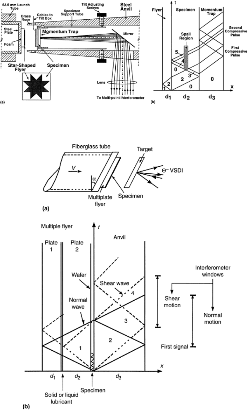
Fig. 5 Soft-recovery, normal impact testing. (a) Test configuration. (b) Lagrangian time-distance (t-X)
diagram for soft recovery experiment. Source: Ref 7
Fig. 6 Pressure-shear high-strain-rate testing. (a) Test configuration. (b) Lagrangian t-X diagram for
pressure-shear high-strain-rate recovery experiment. Source: Ref 18, 19
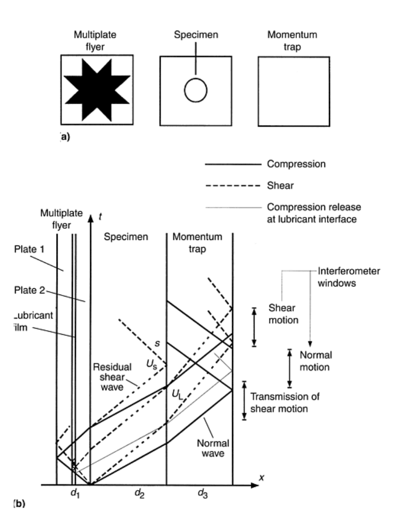
Fig. 7 Pressure-shear wave propagation testing. (a) Test configuration. (b) Lagrangian t-X diagram for
pressure-shear wave propagation recovery experiment. Source: Ref 18, 19
To reduce the boundary release wave effects, guard rings and confining fixtures have been used around the
circumference of the sample (Ref 33, 36, and 37). This requires close tolerances in machining, making the
specimen preparation and assembly difficult. A better approach was proposed by Kumar and Clifton (Ref 38),
who made use of a star geometry for the flyer to redirect the release waves and decrease their damaging effect
at the center. This approach was implemented in experimental studies by a number of researchers (Ref 11, 13,
14, 35, 37, 61, and 62). Three-dimensional simulations on different configurations have also been conducted by
many authors (Ref 13, 36, 63, and 64) for the normal impact configuration, leading to several recommendations
to improve this configuration. Experimental evidence shows that it is difficult to recover brittle specimens
intact, even at moderate stresses of about 2.0 GPa (290 ksi). Results from numerical simulations suggest that
thin flyer plates must be used, which lead to short loading duration. This is difficult to implement in the
pressure-shear recovery experiments since very thin plates produce negligible shear pulse duration.
Investigation of the release effects in the pressure-shear and normal plate impact recovery experiments on
brittle materials shows that the geometry of the plates may be used to mitigate release effects (Ref 16, 17, 18,
and 19). Independently of the geometry of the pressure-shear configuration, some fraction of the energy always

remains in the sample as shear momentum and may affect the radial release waves before they are trapped. The
question of the residual shear pulse, which arises because of the shear strength of the lubricant layer, must
always be addressed.
Normal Plate Impact
Experimental facilities, projectile characteristics, measurement techniques, and specimen preparation and
alignment are discussed in the preceding sections of this article. To illustrate the basic procedure and the
corresponding results, consider first the normal configuration shown in Fig. 5(a), with the t-X diagram of Fig.
5b, in the context of the investigation of inelasticity in a ceramic composite (Ref 7). The fiberglass tube
projectile carries steel and star-shaped Ti-6Al-4V flyer plates that are separated by a low-impedance foam to
prevent reloading of the specimen by reflected waves. The Ti-6Al-4V flyer has sufficiently high yield strength
and acoustic impedance lower than the tested ceramic composite sample. The target assembly consists of an
inner cylinder for supporting the specimen and an outer anvil for stopping the projectile. The anvil has a
disposable brass nose, which absorbs part of the impact energy. The 22 by 22 mm
2
(0.87 by 0.87 in.
2
) specimen
is a thin plate of AlN/AlN/Al composite, backed up by the same size plate, which, ideally, has matching
impedance. This plate flies off the back of the specimen after the main compressive pulse reflects from the rear
surface and returns to the interface.
Experimental Procedure. A 63 mm (2.5 in.) gas gun was used (Ref 7). The specimen characteristics and
relevant test data are reported in Tables 1 and 2. For the purpose of aligning and triggering the oscilloscopes, a
multilayer thin film mask was sputtered onto the impact face of the specimen. Since the AlN/AlN/Al composite
is conductive, a 1 μm thick insulating layer of Al
2
O
3
was first sputtered. Then, by using a mask, a 0.1 μm thick
layer of aluminum was sputtered in the form of four diagonal strip pins at the corners and two ground strips
crossing at the center. Tilt and impactor velocity were measured using the techniques discussed in the section
“Plate Impact Facility” in this article. The normal motion at four points on the rear surface of the momentum-
trap plate was monitored by means of a normal displacement interferometer (NDI) to identify nonplanar
motions that can be correlated with the microcracking process and the unloading waves from the star-shaped
flyer.
Table 1 Properties of materials used in normal impact recovery experiments
Material Density,
g/cm
3
Longitudinal
wave
speed, mm/μs
Transverse
wave
speed, mm/μs
Acoustic
impedance,
GPa · μs/mm
Shear
impedance,
GPa · μs/mm
Hampden
steel
7.86 5.983 3.264 47.03
25.66
Ti-6Al-4V 4.43 6.255 3.151 27.71
13.96
AlN/AlN/Al 3.165 9.50 5.5 30.07 17.41
Source: Ref 7
Table 2 Summary of results from normal impact recovery experiments
Normal stress
Shear stress
Shot No.
Projectile
velocity, mm/μs
GPa ksi MPa
ksi
91-01 0.0804 1.417 206 475
69
91-02 0.1070 1.889 273 633 92
Source: Ref 7
Wave Propagation Analysis. At impact, plane compression waves are produced in both the thin star-shaped
flyer and the specimen. The reflection from the foam-flyer interface unloads the compressive wave, resulting in
a compressive pulse of duration equal to the round-trip travel time through the thickness of the star flyer. When
the compressive pulse reaches the rear surface of the specimen, the gap between the specimen and the
momentum-trap plate produces a reflected wave, which unloads the compressive pulse. Tensile stresses are
generated after crossing the compressed region. By the time this pulse reaches the flyer-specimen interface,

separation between the flyer and specimen has taken place, and the pulse reflection causes compressive
stresses. The initial compressive pulse, minus the pulse reflected at the gap, propagates into the momentum trap
and reflects back. When this tensile pulse reaches the interface between the specimen and the momentum trap,
the momentum trap separates because this interface cannot withstand tension. At this time, the specimen is left
unstressed and without momentum. Because of the impedance mismatch between the specimen and the
momentum trap, an additional compressive wave is reflected at the interface and makes a round trip through the
specimen. This relatively small compressive reloading occurs later than the principal loading of interest and is
expected to have minor influence on the observed damage.
This one-dimensional analysis is valid in the central region of the specimen (Ref 38), where the effects of
diffracted waves from the corners and the edges of the flyer are minimized. The only cylindrical wave, which
passes through the central octagonal region, is a shear wave diffracted from the boundary upon the arrival of a
cylindrical unloading wave at 45°. To fully assess the role of the cylindrical waves diffracted from the edges of
the star and the spherically diffracted waves from the corners of the flyer and the specimen, three-dimensional
elastic computations have been performed (Ref 13). The principal unloading waves that travel in the central
octagonal region are diffracted spherical waves emanating from the corners of the flyer. These waves produce
tensile stresses within the sample. The maximum amplitudes of such stresses occur for transverse tensile
stresses at the rear surface of the specimen. These amplitudes are of the order of 15% of the longitudinal
compressive stress in the incident plane wave. It should be pointed out that this amplitude represents an upper
bound for such stresses. First, in real experiments there is a lack of simultaneity for the time of contact of the
eight corners due to the tilt between the flyer and the specimen. Second, the divergence of the unloading waves
from the corners will induce microcracking near these corners and thereby reduce the level of tensile stresses
that propagate into the central octagonal region to a value below a fracture stress threshold. These features have
been observed systematically in Al
2
O
3
and AlN/AlN/Al composite tested samples.
Experimental Results. A summary of the experiments is given in Tables 1 and 2. The velocity-time histories of
two typical results are given in Fig. 8(a) and (b). The reported stresses are at the interface between the specimen
and the momentum trap. The maximum shear stress is given. The stress-time histories at the front surface of the
momentum trap can be read from the secondary vertical axis. Dashed lines in the plot are the elastic solution
results, which are used as a reference to discuss several observed inelastic effects. The main compressive pulse,
with duration between 240 and 195 ns, is followed by a second compressive pulse corresponding to the tensile
pulse generated by an intentional gap of 30 and 85 ns in Fig. 8(a) and (b), respectively. The third pulse results
from the reflection of the main pulse at the interface between the specimen and the momentum trap. Its close
resemblance to the main pulse is an indication of the dominance of plane waves in the central region of the
sample. In the experiment at lower impact velocity (Fig. 8a), the compressive pulse has the full amplitude of the
elastic prediction. This implies that, initially, the material did not undergo inelastic processes at this level of
stresses. The small reduction in amplitude at the end of the pulse can be interpreted from the analysis of release
waves from the star-shaped flyer corners (Ref 13). The tail at the end of the first compressive pulse appears to
be the result of the inelastic strain rate produced by the nucleation and propagation of microcracks (Fig. 8a). If
so, the duration of the tail can be associated with the time required for the stress, at the wave front, to relax to
the threshold value required for initiating crack propagation. Strong evidence of microcracking is found in the
attenuation and spreading of the second compressive pulse. In Fig. 8(b), some indication of inelasticity in
compression appears toward the end of the pulse. This feature is consistent with the increase in dislocation
density, within the AlN filler particles, the AlN reaction product, and the Al phase, observed in transmission
electron microscopy (TEM) samples made from the recovered specimens (details can be found in Ref 7).

Fig. 8 Velocity-time profiles for normal impact recovery experiments. (a) Profile for shot No. 91-01 in
Table 2. Second compressive pulse is attenuated due to material dynamic failure in tension. (b) Profile
for shot No. 91-02 in Table 2. A strong spall signal and attenuation of the first compressive pulse are
observed. Source: Ref 7
Pressure-Shear Plate Impact
Inclining the flyer, specimen, and target plates with respect to the axis of the projectile produces compression-
shear loading. By varying the inclination angle, a variety of loading states may be achieved. For small angles of
inclination, small shear stresses are produced, which can be used to probe the damage induced by the
accompanying pressure. This pressure-shear plate impact experiment was modified by Ramesh and Clifton (Ref
6) to study the elastohydrodynamic lubricant response at very high strain rates. The idea of recovery pressure-
shear plate impact experiment was presented by Nemat-Nasser et al. (Ref 40), Espinosa (Ref 41), and Yadav et
al. (Ref 65) and was first successfully implemented to study the response and failure modes of alumina
ceramics by Machcha and Nemat-Nasser (Ref 16) and later by Espinosa et al. (Ref 17, 18, 19, and 52) in their
studies of dynamic friction and failure of brittle materials.
Wave Propagation Analysis. The Lagrangian time-distance (t-X) diagrams for pressure-shear high-strain-rate
and wave propagation configurations, designed for specimen recovery, are shown in Fig. 6(b) and 7(b). In the
case of pressure-shear high-strain-rate experiments, the specimen is a thin wafer, 100 to 500 μm thick,
sandwiched between two anvil plates. At impact, plane compression waves and shear waves are produced in
both the impactor and the target. Since the shear wave velocity is approximately half the longitudinal wave
velocity, a thin film with very low shear resistance needs to be added to the flyer plate such that the arrival of
the unloading shear wave, to the impact surface, precedes the arrival of the unloading longitudinal wave
generated at the back surface of the second flyer plate. The longitudinal and shear wave fronts arriving to the
anvil-free surface are shown in Fig. 6(b). These wave fronts determine the longitudinal and shear windows
measured interferometrically. These velocity histories contain information on the sample stress history as
discussed in the next paragraph. A similar wave analysis applies to the wave propagation pressure-shear
configuration (Fig. 7b).
According to one-dimensional elastic wave theory (Ref 5), the normal stress is given by σ = ρc
1
u
0
/2, in which
ρc
1
is the flyer and anvil longitudinal impedance, and u
0
is the normal component of the impact velocity V (i.e.,
u
0
= V cos θ). The strain rate is given by the velocity difference between the two faces of the sample divided by
its thickness (i.e., = (ν
f
- ν
a
)/h = (ν
0
- ν
fs
)/h), where ν
f
and ν
a
are the flyer and anvil transverse velocities,
respectively, at their interfaces with the specimen, and ν
0
=V sin θ and ν
fs
are, respectively, the transverse
components of the impact velocity and the velocity of the free surface of the anvil plate. The integration of the
strain rate over time gives the shear strain γ(t). One-dimensional elastic wave theory can be used again to
express the shear stress in terms of the measured free surface transverse velocity (i.e., τ = ρc
2
ν
fs
/2), where ρc
2
is
the anvil shear impedance. These equations can be used to construct τ - γ curves at strain rates as high as 1 ×
10
5
s
-1
and pressures in the range of 2 to 5 GPa (290 to 725 ksi). It must be emphasized that this analysis is
based on the assumption that inelasticity takes place only in the specimen. An investigation of this requirement
at high strain rate and temperatures can be found in Ref 42.
Numerical simulations have been performed by Machcha and Nemat-Nasser (Ref 23) for the pressure-shear
recovery experiments. The results confirm the advantages of the star-shaped geometry. Machcha and Nemat-
Nasser positioned the star-shaped flyer as a second flyer plate, which does not fully mitigate lateral release
waves, in the central portion of the sample. Espinosa and coworkers (Ref 18, 19) positioned the star-shaped
flyer plate as the first plate of the multiplate flyer assembly. The selection of materials for the manufacturing of
flyer plates depends on the application for which experiments are conducted. In the characterization of hard
materials, demanding requirements are placed on the manufacturing of flyer and momentum-trap plates. These
plates must be hard enough in compression and shear to remain elastic at the high stress levels required for the
inelastic deformation of the specimen. The momentum trap must be strong enough in tension to prevent failure
at 45° when the shear wave propagates through the unloaded region adjacent to the rear surface of the
momentum trap. These requirements are met by using Speed Star (Carpenter Technology Corp.—Specialty
Alloys, Reading, PA) steel plates with a 0.2% offset yield stress greater than 2200 MPa (320 ksi) in shear and a
tensile strength in excess of 1500 MPa (220 ksi). Another important feature in the selection of the flyer material
is that its longitudinal and shear impedances must be smaller or equal to those of the specimen. In this way, a

single compression-shear pulse is introduced in the sample. Moreover, the longitudinal and shear impedances of
the momentum-trap plate must match the impedances of the sample to avoid wave reflections at the specimen
momentum-trap interface. Density, wave speeds, and impedances for the materials used in this investigation are
reported in Table 3.
Table 3 Properties of materials used in pressure-shear impact recovery experiments
Wave speed,
mm/μs
Impedance,
GPa · mm/μs
Material Density
kg/m
3
c
1
c
2
ρc
1
ρc
2
Speed-Star Steel
8138 5.852
3.128
47.62
25.46
TiB
2
4452 10.93
7.3 48.66
32.5
Al
2
O
3
/SiC 3890 10.56
6.24 41.08
24.27
Source: Ref 19
Experimental Procedure. The 76 mm (3.0 in.) gas gun described in the section “Plate Impact Facility” was used.
The multiplate flyer and target plates were made of Speed Star steel. The specimens were made with two types
of ceramics. In the high-strain-rate pressure-shear experiment, an Al
2
O
3
/SiC nanocomposite wafer was used.
TiB
2
plates were employed in the wave propagation pressure-shear experiments. In the latter case, two
specimen configurations were investigated. The first one consisted of a square specimen with the same
dimensions as the star-shaped flyer. The second configuration consisted of a hollow square steel plate in which
a TiB
2
ceramic rod 12.7 mm (0.5 in.) in diameter was shrunk fitted.
The target rear surface was polished, and then a thin layer of positive photoresist was deposited using a
spinning machine. A holographic phase grating was constructed by interference of two laser beams. The angle
between the beams was selected such that a sinusoidal profile with 1000 lines/mm was obtained. This grating
was used to measure the normal and transverse displacements by means of a variable sensitivity displacement
interferometer (VSDI) (Ref 52). The signals generated by each interfering beam pair were monitored by silicon
photodetectors.
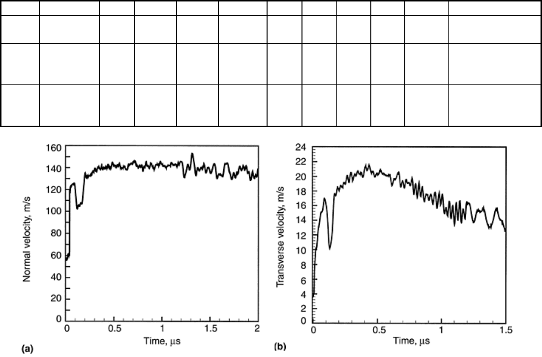
Experimental Results. A summary of these experiments is presented in Table 4. The normal velocity-time
profile obtained from the high-strain-rate pressure-shear recovery configuration is shown in Fig. 9(a). The
normal particle velocity shows a velocity reduction after an initial jump indicating the presence of a small gap
between the Al
2
O
3
/SiC nanocomposite and the multiplate flyer. Upon reverberation of waves within the
specimen, the normal velocity rises to a value of about 140 m/s (460 ft/s) at approximately 0.4 μs and remains
almost constant until release waves from the boundary reach the observation point. The peak normal stress in
this shot, computed according to σ = ρc
1
u
fs
/2, reaches 3.45 GPa (500 ksi). The transverse particle velocity
history for this experiment is shown in Fig. 9(b). The velocity rises progressively and then drops for a few
nanoseconds. Since in this experiment, shear motion is transferred by friction, a reduction in normal traction at
the specimen-steel plate interface results in a drop of the transmitted shear motion. When the gap closes, the
transverse velocity increases until it reaches a maximum value of 22 m/s (72 ft/s) at about 500 ns. It then decays
continuously while the normal velocity remains constant (Fig. 9a). The maximum shear stress, given by τ =
ρc
2
ν
fs
/2, is 280 MPa (41 ksi). This value is well below the expected shear stress of 575 MPa (83 ksi), assuming
elastic material response. The progressive reduction in anvil-free surface transverse velocity implies a variable
strain rate and absence of a homogeneous stress state in the sample. In this experiment, round plates were used
and the sample was precracked through a sequence of microindentations in a diameter of 38 mm (1.5 in.)
Lateral trapping of release waves was attempted by forming a circular crack with the unloaded sample in the
central region. Despite these efforts, the degree of damage was severe enough that the ceramic sample was
reduced to fine powder upon unloading. This feature of material pulverization upon unloading was investigated
by Zavattieri et al. (Ref 22) by simulating compression-shear loading on representative volume elements at the
grain level. These investigators show that a ceramic microstructure containing a dilute set of microcracks may
pulverize in unloading due to the stored elastic energy within the grains.
Table 4 Summary of parameters for pressure-shear recovery experiments
Shot
No.
Specimen
Specimen
thickness
Impactor
thickness
Target
thickness
Projectile
velocity
Tilt,
mrad
Configuration
mm in. mm in. mm in. m/s ft/s
7-
1025
Al
2
O
3
/SiC
0.54 0.021 2.42–
3.65
0.095–
0.144
7.99 0.31 148 486 1.3
High strain-rate
recovery
7-
1115
TiB
2
4.15 0.163 1.04–
2.55
0.041–
0.100
4.53 0.18 130 427 20.3
Wave
propagation
recovery
8-
0131
TiB
2
8.9 0.35 0.92–
3.0
0.036–
0.12
4.05 0.16 133 436 1.32 Wave
propagation
recovery
Source: Ref 19
Fig. 9 Velocity histories from a pressure-shear high-strain-rate experiment (shot No. 7-1025 in Table 4).
(a) Normal velocity history. The time scale starts with the arrival of the longitudinal wave to the anvil-
free surface. (b) Transverse velocity history. The time scale starts with the arrival of the shear wave to
the anvil-free surface. Source: Ref 18, 19
In the case of the wave propagation pressure-shear recovery configuration, round and square-shaped TiB
2
plate
specimens were used. The longitudinal and shear waves recorded in the case of the square-shaped TiB
2
specimen are shown in Fig. 10(a) and 10(b), respectively. The velocity profile in the first microsecond is shown
in solid lines, while the remaining part of the signal is shown in dashed lines. Figure 10(a) shows the normal
velocity rises to a value predicted by one-dimensional elastic wave theory. After approximately 200 ns, the
longitudinal particle velocity progressively decays and then rises again at approximately 500 ns. This
longitudinal velocity history is very close to the one-dimensional elastic wave propagation prediction if the
effect of spherical waves emanating from the star-shaped flyer corners is taken into account (Ref 13). Another
source of stress decay is the presence of a thin polymer layer in the multiplate flyer. As previously discussed,
longitudinal stress decay occurs until a homogeneous deformation state is reached in the polymer film. The
transverse particle velocity shown in Fig. 10(b) also presents clear features. Upon wave arrival to the back
surface of the momentum-trap plate, an in-plane velocity of about 10 m/s (33 ft/s) is measured
interferometrically. After shear wave arrival, according to the t-X diagram discussed previously, the transverse
velocity rises to a maximum of 38 m/s (125 ft/s). This value is below the shear wave velocity predicted by one-
dimensional wave propagation theory. Hence, the material clearly exhibits an inelastic behavior in shear. At
approximately 800 ns, the transverse velocity decays progressively.
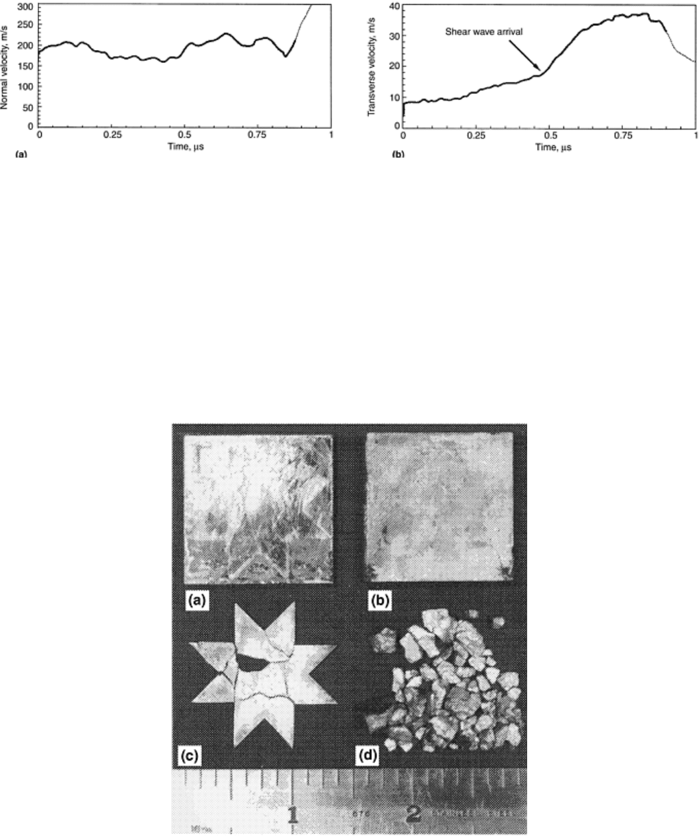
Fig. 10 Velocity histories from a pressure-shear wave propagation experiment (shot No. 8-0131 in Table
4). (a) Normal velocity history. The time scale starts with the arrival of the longitudinal wave to the
momentum-trap-free surface. (b) Transverse velocity history. The time scale starts with the arrival of the
shear wave to the momentum-trap-free surface. Source: Ref 19
Understanding these complex velocity histories requires complete three-dimensional simulations of the
compression-shear experiment including damage and tilt effects. In this experiment, the steel plates are fully
recovered. In contrast to the shrink-fitted specimen, the ceramic specimen is fragmented with varying fragment
sizes (Fig. 11). The larger fragment is several millimeters in size, but its location in the square plate could not
be identified unambiguously. In this case, the star-shaped flyer also is fragmented in the central region. In
addition, long cracks are observed running parallel to the edges. Severe indentation is observed in the second
flyer plate, although its hardness was measured to be 55 HRC. In this configuration, the momentum-trap plate
remains intact with no cracks observable to the naked eye. Additional details can be found in Ref 18 and 19.
Fig. 11 Optical micrograph of recovered plates from a pressure-shear wave propagation experiment
(shot No. 8-0131 in Table 4). (a) Second flyer plate. (b) Back momentum-trap plate. (c) Star-shaped flyer
plate. (d) Fragmented specimen. Source: Ref 19
References cited in this section
1. P. Kumar and R.J. Clifton, Dislocation Motion and Generation in LiF Single Crystals Subjected to
Plate-Impact, J. Appl. Phys. ,Vol 50 (No. 7), 1979, p 4747–4762
