ASM Metals HandBook Vol. 17 - Nondestructive Evaluation and Quality Control
Подождите немного. Документ загружается.

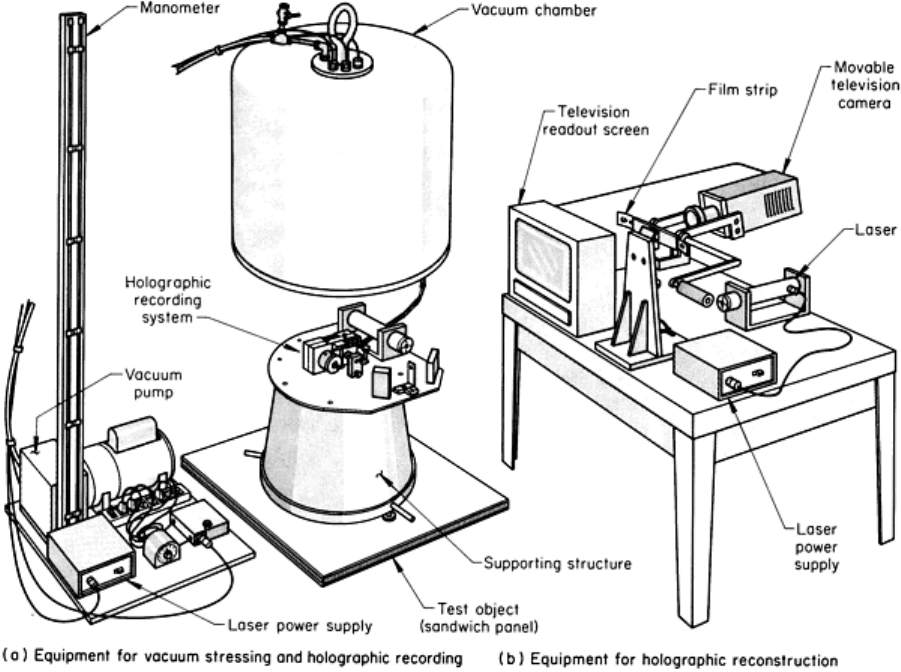
Fig. 10 Portable holographic analyzer for the inspection of sandwich panels with use of vacuum stressing.
See
description in text.
Reflection Holographic Systems. In a simplified type of portable system, a tripod-mounted laser and spatial filter
project light directly through a holographic plate fastened to the test object. A reflection hologram is formed by
interference between the light traveling through the plate and the light reflected back to the plate from the object. In this
system, the reference beam and the object beam strike the emulsion from opposite sides of the plate, resulting in the
reconstruction of a virtual image produced by reflection. This configuration differs from the holographic systems
described earlier, in which the two recording beams strike the plate from the same side and, during reconstruction, the
virtual image is produced by transmission.
An important consideration in designing reflection holographic systems is that reflection holograms are more sensitive
than transmission holograms to photographic emulsion shrinkage, which may take place during the development and
drying processes. This shrinkage causes the image formed during reconstruction to be produced at a slightly shorter
wavelength (a hologram recorded with red laser light will reconstruct best in yellow or green light). Unless the
reconstructing light matches this shorter wavelength, the image will be quite faint. Therefore, white light, which contains
all the required wavelengths for efficient image production, is often used as the reconstructing reference beam instead of
laser light.
Because, as described above, the film plate also serves as a beam splitter and can be mounted to the test object itself,
reflection holographic systems can be quite insensitive to object vibration. The major critical stability requirement is the
relationship between the object and the holographic plate fastened to it. If the emulsion shrinkage is fairly uniform and the
holographic plate is in close proximity to the test object, the image formed will be bright and clear. The plate must be
dried carefully, however, to avoid variations in emulsion thickness, which would cause variation in the color of the image.
Because the diffraction of light changes with color, variations in color will cause smearing of the image and loss of
resolution. The greater the distance from the object to the plate, the greater the smearing.
Portable systems can be used in the following cases:
• Field inspection
•
When the size or configuration of a test object is such that it is more practical to attach the holographic
system to the object than vice versa
• When the test object is in an environment or in a structure required as part of the experiment
Portable holographic systems are usually designed to inspect a specific part or a range of small parts. The questions that
establish criteria for designing a portable system are the following:
• How is the system to be powered?
• How is stability between the
system and the test object to be maintained both during and between
exposures?
• How can critical adjustments be made or eliminated?
• How is the photographic plate to be handled and processed?
• How can the holographic components and the stressing fixture b
e designed into a workable system
within the definition of portable?

Optical Holography
Revised by James W. Wagner, The Johns Hopkins University
Typical Holographic Testing Applications
Among the applications for which holographic testing is utilized are the following:
• Inspection of sandwich structures for debonds
• Inspection of laminates for unbonded regions
• Inspection of metal parts for cracks
• Inspection of hydraulic fittings
• Measuring of small crack displacements
• Vibration analysis of turbine and propeller blades
• Holographic contouring
• Characterization of composite materials
Optical Holography
Revised by James W. Wagner, The Johns Hopkins University
Inspection of Sandwich Structures for Debonds
A sandwich structure usually consists of face sheets separated by a lightweight core. The face sheets are designed to carry
in-plane loads; the core is designed to stiffen the face sheets and prevent them from buckling and to carry normal loads in
compression or shear. The core can be a solid material, such as balsa wood, or a cellular material, such as foam plastic or
honeycomb construction. The face sheets and core are usually held together by an adhesive or braze material.
The extensive use of sandwich structures in widely varying applications has created some unusual inspection problems.
The main area of interest is the quality of the attachment of the face sheets to the core; large areas of structures must be
inspected inexpensively for unbonded or unbrazed areas (debonds) and for poorly bonded or brazed regions. The
inspection for poorly bonded or brazed regions has not yet been satisfactorily accomplished on a production basis, but is
currently the subject of various research programs. A secondary area of interest is the edge-closure assembly, which
surrounds the sandwich structure. The configuration of the closure varies depending on whether the sandwich is brazed or
bonded and on the types of materials involved. Sandwich structures cause inspection problems because of the number of
parts being joined together and the abrupt changes in thickness or solidity of the assembly. An additional complication
arises in designing a holographic inspection system for sandwich structures in that structures range in area from several
square inches to several square feet and their contours vary from simple flat panels to complex curved shapes, such as
helicopter rotor blades. Both sides and all edges of the structures must be inspected.
When inspecting sandwich structures, it is necessary to determine which stressing technique or combination of techniques
will best detect the types of flaws likely to be present. If several techniques are chosen, it must be decided whether to
apply them simultaneously or sequentially. The two stressing techniques that have been found to work well for the routine
inspection of sandwich structures are thermal stressing (Fig. 11) and vacuum stressing (Fig. 4), although stress for
inspection can be provided by acoustical loading (Fig. 3), fatigue loading (Fig. 5), or impact loading.
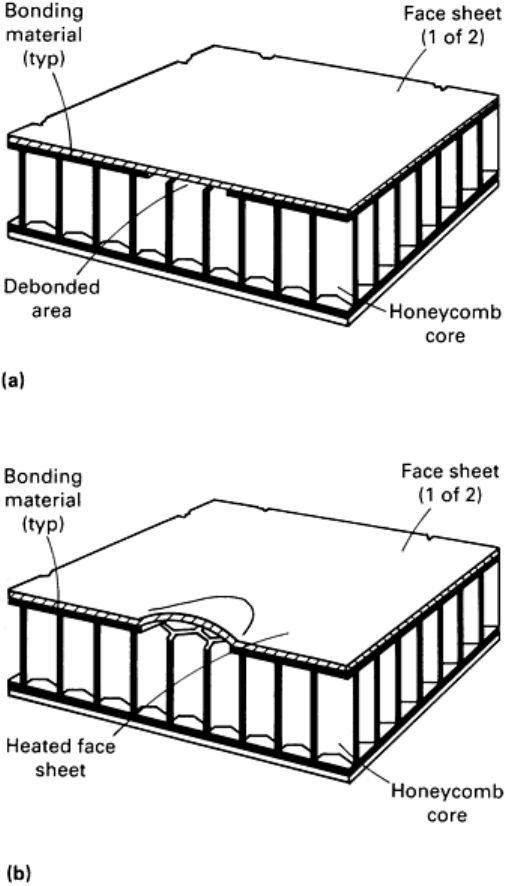
Fig. 11 Honeycomb-
core panel illustrating the detection of debond by thermal stressing. (a) Section through
the region of debond. (b) Same section as in (a) showing bulge in fa
ce sheet over the region of debond, caused
by gentle heating of the face sheet
Techniques for inspecting sandwich structures are well established and documented (Ref 20). Most inspection of
sandwich structures is being done, and probably will be done, using CW techniques, with pulsed-laser techniques being
used only for special applications.
Example 1: Detection of a Debond in a Honeycomb-Core Panel With Thermal-
Stressing Holographic Techniques.
As an example of holographic inspection using thermal stressing, assume that a honeycomb-core sandwich panel, such as
that illustrated in Fig. 11(a), contains a debond. If the face sheet over the debond is gently heated, the region over the
debond will become hotter faster because the heat in that region is not conducted away to the core. The result of this
differential-temperature field is a slight bulge in the heated face sheet (Fig. 11b). Using either real-time or double-
exposure time-lapse holographic techniques, an image will be formed in which the region of the bulge is contoured by a
set of fringes representing lines of constant displacement between the two images.
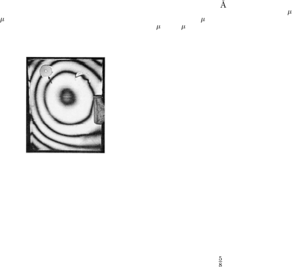
A typical set of fringes caused by a debond in a honeycomb-core sandwich panel is illustrated by the interferogram in Fig.
12, which demonstrates the sensitivity of inspection by thermal stressing. This interferogram was obtained using the
double-exposure technique and a pulsed ruby laser, which has a wavelength of 694 nm (6940 ) (Table 1). Using Eq 3, it
can be seen that each fringe, except the first, represents an out-of-plane displacement of 0.694/(2 sin 90°), or about 0.33
m (13 in.). The region above the debond in the panel, which had a face sheet 500 m (0.02 in.) thick and was heated
only about 2.8 °C (5 °F), has a maximum displacement of about 3 m (120 in.), or only about 0.6% of the face sheet
thickness.
Example 2: Holographic Detection
of a Debond in a Sandwich
Structure Using the Vacuum-
Stressing Method.
Inspection by vacuum stressing has also been found to
be effective for detecting debonds in sandwich
structures. Figure 10 shows the essential components
of a portable holographic analyzer for the inspection
of sandwich panels. This analyzer consists of two
separate sets of equipment: one set for vacuum
stressing and holographic recording (Fig. 10a) and
one set for holographic reconstruction (Fig. 10b). The
holographic recording system is mounted on the top
of a hollow supporting structure that rests on the test
panel. The recording system contains a 3-mW CW
helium-neon laser and, through the use of suitable
optical components, encompasses a 460 mm (18 in.)
diam circular field of view of the portion of the panel
surface beneath the supporting structure.
During an inspection, the vacuum chamber, which is
made of fiberglass, is lowered over the recording
system until contact is made with the surface of the
panel. A first exposure is made of the panel in its
unstressed state. A second exposure is made when the
internal pressure has been reduced by approximately 7
kPa (1 psi). The pressure of the ambient air in the core voids pushes the face sheets out at unbonded regions. The double-
exposure hologram is recorded as a circular field 8 mm (0.3 in.) in diameter on a 16 mm ( in.) film strip. The film is
then advanced, the vacuum is released, the system is moved to the next location on the panel, and the sequence is
repeated. The total time required for constructing a double-exposure hologram is usually about 1 min or less. By using a
film strip 2030 mm (80 in.) long, it is possible to record a total of more than 200 double-exposure holograms.
A typical commercial holographic analyzer for the inspection of sandwich structures is illustrated in Fig. 13. It
consists of a 3.7 × 2.4 m (12 × 8 ft) table supported on air bearings. On this table is a part-holding mounting plate, which
is supported by two 1220 mm (48 in.) diam trunnion plates. The mounting plate can be rotated and translated to view
either flat panels or curved shapes. The holographic system usually uses a 50-mW helium-neon laser, but can also use
higher-powered argon lasers. The part to be inspected is held in place on the mounting plate by a series of vacuum cups or
clamps. Thermal, vibrational, pressure or vacuum stressing can be applied. A part measuring up to 1.5 × 1.8 m (5 × 6 ft)
can be inspected with this analyzer. Other analyzers are available that are designed to handle either smaller parts or larger
parts (up to 1.8 × 6.1 m, or 6 × 20 ft).
Fig. 12 Double-exposure time-lapse inter
ferogram of a
thermally stressed honeycomb-
core sandwich panel
showing a fringe pattern (arrow) contouring a region of the
front face sheet over a debond. The panel had metal face
sheets 500 μ
m (0.02 in.) thick and was heated about 2.8
°C (5 °F) between exposures, which were made with a
pulsed ruby laser. The fringes indicate a maximum
displacement over the debond of 3 μm (120 μ
in.). The
background fringes were caused by general movement of
the face sheet due to heating.
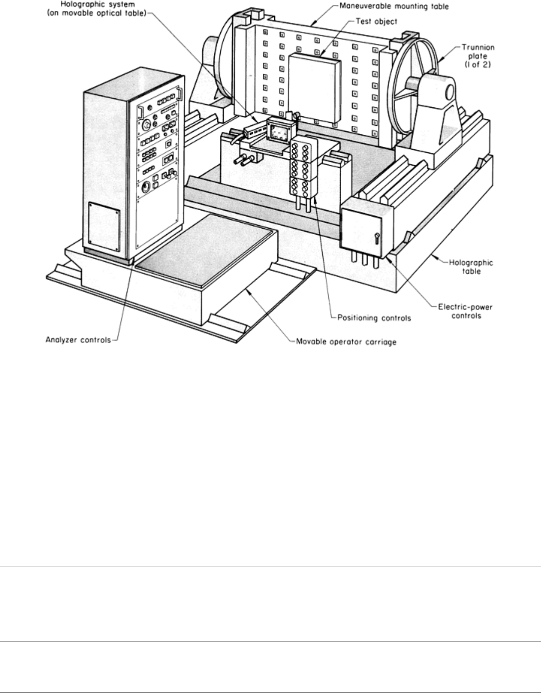
Fig. 13 Commercial holographic analyzer used for the inspection of sandwich structures.
See text for
description.
Approximately 0.19 or 0.28 m
2
(2 or 3 ft
2
) of a part surface can be viewed in a single hologram with the analyzer
illustrated in Fig. 13. The exposure and processing of the hologram are controlled automatically by the analyzer. With the
50-mW helium-neon laser, approximately 2.3 m
2
(25 ft
2
) of surface can be inspected per hour. Either double-exposure or
real-time interferograms can be made with this analyzer. Using the real-time technique, the inspected areas can be
recorded by taking still photographs through the hologram or preferably by recording the transient patterns on videotape.
Still photographs give an indication of obvious flaws, but far smaller flaws can be detected by an experienced inspector
viewing a sweeping fringe pattern. A library of videotapes showing various flaws can be used as a training and qualifying
aid. As in other inspection techniques, standards and qualifying procedures must be established. Application and further
development of automated fringe interpretation methods could also be used to advantage for this type of inspection.
Reference cited in this section
20.
R.C. Grubinskas, "State of the Art Surv
ey on Holography and Microwaves in Nondestructive Testing," MS
72-9, Army Materials and Mechanics Research Center, Sept 1972, p a40-46
Optical Holography
Revised by James W. Wagner, The Johns Hopkins University
Inspection of Laminates for Unbonded Regions
Standard optical holographic systems are readily used to identify the presence of flaws in laminated composites and
structures. Generally, double-exposure techniques are the most convenient, although both real-time techniques and time-
average techniques (for oscillating systems) can also be used. Because the most common flaw in laminates is a lack of
bonding, the critical problem is to select the most suitable stressing technique that will reveal the presence of the
unbonded region by inducing some differential movement between the bonded and unbonded regions.
Example 3: Holographic Tire Analyzer for Detecting Flaws With Vacuum-
Stressing Technique.
An example of a laminated composite is the pneumatic tire, which is constructed of layers of rubber and fabric. (Some of
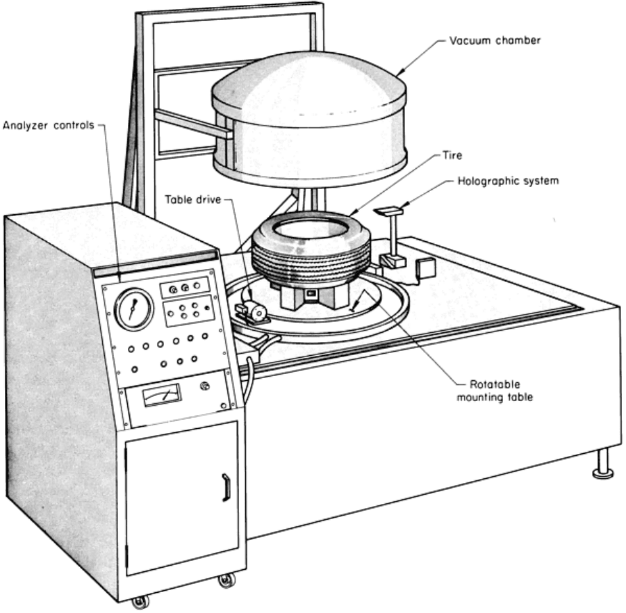
the fabrics used in modern tires contain steel wires.) The commercial holographic tire analyzer illustrated in Fig. 14 is
capable of inspecting tires ranging in size up to a maximum outside diameter of 1145 mm (45 in.) at a rate of more than
12 tires per hour when auxiliary semiautomatic options are employed. The inspection procedure uses the vacuum-
stressing technique described previously; a double-exposure interferogram is made of each quadrant of the inner walls of
the tire undergoing inspection. Flaw anomalies are manifested by minute changes in the inner-wall topography occurring
as a result of the pressure differential existing between the unvented tire flaws and the evacuated chamber.
Fig. 14 Commercial holographic analyzer used for the inspection of pneumatic tires.
See text for a description
of the inspection procedure.
Example 4: Holographic Tire Analyzer for Detecting Defects Using 345 kPa (50
psi) Inflation Pressure.
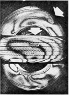
A different type of holographic tire analyzer employed to obtain the interferogram shown in Fig. 15 used inflation to 345
kPa (50 psi) rather than vacuum stressing. With this analyzer, both of the sidewalls and the tread portion of the tire can be
inspected simultaneously for all unbonded regions.
Fig. 15 Double-exposure time-
lapse interferogram of a defective pneumatic tire that was stressed by inflation
to 345 kPa (50 psi) between exposures. The contoured fringe patterns (arrows) indicate regions of the sidewall
and tread where there is no bond betwe
en layers of the cured tire. General movement of the tire during
inflation caused the background fringes.
Additional Techniques for Stressing Laminates. Other laminates can be stressed by heating (as with printed
circuit boards), by ultrasonic excitation, and by the addition and removal of a mechanical load.
Example 5: Holographic Inspection of Coprene Rubber-Stainless Steel Laminate
Using Mechanical Loading Technique.
An example of the use of the mechanical-loading method is a simple rubber-steel laminate that was stressed in cantilever
bending while clamped along one edge. Holographic exposures made before and after stressing reveal a field of closely
spaced fringes (Fig. 16) due to anelastic effects that prevent full recovery. Local perturbations in this field due to an
unbonded region between the rubber sheet and the metal substrate can be readily identified as an anomaly in the fringe
pattern.
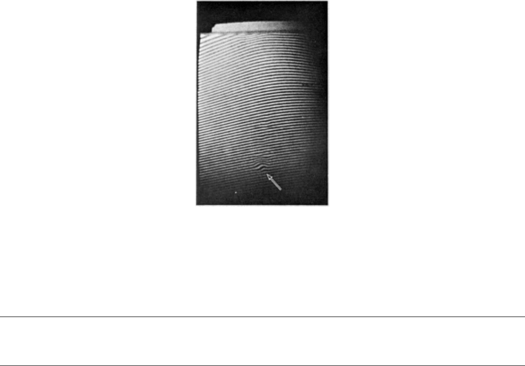
Fig. 16 Double-exposure time-lapse interferogram of a defective rubber-steel laminate that was mecha
nically
stressed between exposures showing a local perturbation in the fringe pattern (arrow) over an unbonded
region. The laminate was 125 mm (4.92 in.) long by 90 mm (3.5 in.) wide and was composed of a 0.94 mm
(0.037 in.) thick sheet of coprene rubber b
onded to a 1.93 mm (0.075 in.) thick sheet of stainless steel. The
rubber face was painted with a bright white reflecting paint to aid in holographic inspection.
Optical Holography
Revised by James W. Wagner, The Johns Hopkins University
Inspection of Metal Parts for Cracks
Optical holographic inspection has not proved to be an effective method for finding even large cracks in metal parts. The
primary reason for this is the difficulty of stressing the test object in such a manner as to create a difference in
displacement that is easily detectable optically. Speckle-pattern techniques can be useful for the detection of in-plane
displacements associated with surface cracks.
In general, only those cracks greater in length than the thickness of the part are detectable by optical holographic
inspection. Several stressing methods have been found to be useful, such as mechanical stressing by means of loading
fixtures or interference fasteners as well as thermal stressing by means of heat lamps or cold liquids or solids. Either real-
time techniques or double-exposure techniques can be used. Also, high-resolution techniques, such as phase stepping and
heterodyne holographic interferometry, have been used (see the section "Interpretation of Inspection Results" in this
article). Time-average time-lapse techniques are generally not successful for detecting the effects of cracks on vibratory
patterns.
Example 6: Holographic Inspection of Hydraulic Fittings to Detect Cracks.
An instance of the successful detection of cracks by optical holography was the inspection of small hydraulic fittings.
Radiographic studies using x-rays, eddy current testing, and other forms of nondestructive inspection did not provide
reliable detection of these small cracks or sufficient data on crack growth characteristics.
To solve the inspection problem, conventional double-exposure time-lapse holography was employed using a 15-mW
helium-neon laser and portable optical components. The plate holder was a conventional static type and held 100 × 125
mm (4 × 5 in.) glass plates. The entire optical system was mounted on a commercial 1.2 × 2.4 m (4 × 8 ft) vibration-
isolation (holographic) table.
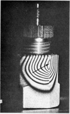
Inspection consisted of first making a holographic exposure of a fitting held statically in a vise-type clamping fixture.
After the first exposure, a mating fitting was screwed into the test fitting to approximate normal in-use loading, and a
second exposure was then made on the same holographic plate. The resulting interferogram is shown in Fig. 17. Each
interference fringe in this reconstruction represents a displacement between exposures of approximately one-half the
wavelength of the helium-neon light (λ = 633 nm, or 6330 Å), or about 0.33 μm (13 μin.). The discontinuity in the fringe
pattern indicates that relative motion, or slippage, occurred along the front vertical edge of the fitting during loading.
Inspection at still higher loads revealed a small crack along that edge.
Fig. 17 Double-
exposure interferogram of a cracked hydraulic fitting. The fitting was stressed between
exposures by having a mating fitting screwed into it. The holocamera used a 15-mW heliumneon
laser. The
discontinuity in the fringe pattern (arrow) was caused by a small crack in the fitting.
The use of optical holographic inspection in this application permitted relatively inexperienced personnel to pinpoint
small cracks in several hydraulic fittings and to study the propagation of these cracks under varying load conditions. This
brief study program required approximately 6 h of engineering time and no special fixturing or tooling.
Example 7: Small Crack Displacement Measurements Using Heterodyne
Holographic Interferometry.
As mentioned above, the small out-of-plane displacements associated with most cracks make it difficult to apply
conventional (homodyne) holographic interferometry techniques. Still, small displacements do occur and can be
visualized holographically using high-resolution techniques. For example, Fig. 18 shows the results of a heterodyne
analysis of a region of a holographic interferogram near a surface-breaking crack. Total displacements of only 5 to 6 nm
(50 to 60 Å) were observed in this case with a background noise floor of about 0.6 nm (6 Å).
