ASM Metals HandBook Vol. 14 - Forming and Forging
Подождите немного. Документ загружается.

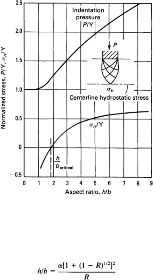
Fig. 22 Variation of the normalized indentation pressure (P
/Y where Y is the yield strength) and the normalized
centerline hydrostatic stress (σ
h
/Y) with h/b ratio as calculated from slip-line field analysis.
For example, in extrusion, h/b is approximated by:
where α is the die half-angle and R is area reduction. Taking h/b = 1.8, the relationship between α and R that produces
tensile hydrostatic stress at the centerline can be calculated. The result is given in Fig. 23, which is shown to be similar to
the relationship predicted by upper bound analysis (Fig. 19). The correlation is remarkable in view of the dissimilarity in
die shape between extrusion and double indentation. Furthermore, the similarity emphasizes that the flow mode for defect
formation in the upper bound method is physically equivalent to the development of tensile hydrostatic stress.
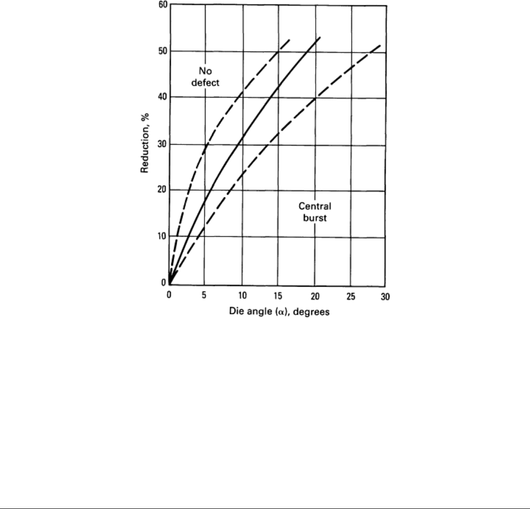
Fig. 23 Prediction of central burst in wire drawing by the tensile stress criterion and slip-
line field analysis of
double indentation. The range of predictions by upper bound analysis (Fig. 19) is shown by dashed lines.
As in the case of the upper bound method, the existence of a tensile hydrostatic stress does not ensure fracture, but it is a
necessary ingredient. The material structure must be considered in conjunction with the tensile stress. In other words, the
upper bound and tensile stress criteria are useful for defining approximate deformation limits and successful process
parameters, but more detailed criteria or models are required to provide more exact values. An experimental-analytical
approach, then, would be most useful in which an experimental value reflecting the inherent material ductility is
determined first (this value is used to define a point on the fracture strain locus), followed by development of the rest of
the fracture limit line, as in Fig. 10, 11, 12, 14, 16, and 17.
References cited in this section
4. F.A. McClintock, J. Appl. Mech. (Trans. ASME), Vol 90, 1968, p 363
5. Z. Marciniak and K. Kuczynski, A Model of Localized Thinning in Sheet Metalforming, Int. J. Mech. Sci.,
Vol 9, 1967, p 609
6. P.W. Lee and H.A. Kuhn, Fracture in Cold Upset Forging--A Criterion and Model, Metall. Trans. A,
Vol
4A, 1973, p 969-974
7. M.G. Cockcroft and D.J. Latham, Ductility and the Workability of Metals, J. Inst. Met., Vol 96, 1968, p 33-
39
8. B. Avitzur, Metal Forming--Processes and Analysis, McGraw-Hill, 1968
9. W.M. Evans and B. Avitzur, "Die Design for Drawing Extrusion," Paper MF67-
582, Society of
Manufacturing Engineers, 1967
10.
B. Avitzur, "Strain Hardening and Strain Rate Effects in Plastic Flow Through Conical Converging Dies,"
Paper 66-Prod-17, American Society of Mechanical Engineers, 1966
11.
R. Hill, On the Inhomogeneous Deformation of a Plastic Lamina in a Compression Test, Philos. Mag.,
Vol
41, 1950, p 733
12.
J.F. Nye, Experiments on the Plastic Compression of a Block between Rough Plates, J. Appl.
Mech. (Trans.
ASME), Vol 19, 1952, p 337
Workability Theory and Application in Bulk Forming Processes
Howard A. Kuhn, University of Pittsburgh
Applications
The fracture criteria discussed previously in this article can be used as tools for troubleshooting fracture problems in
existing processes or for designing/modifying processes for new products. In either case, graphical representation of the
criteria permits independent consideration of the process and material parameters in quantitative or qualitative form.
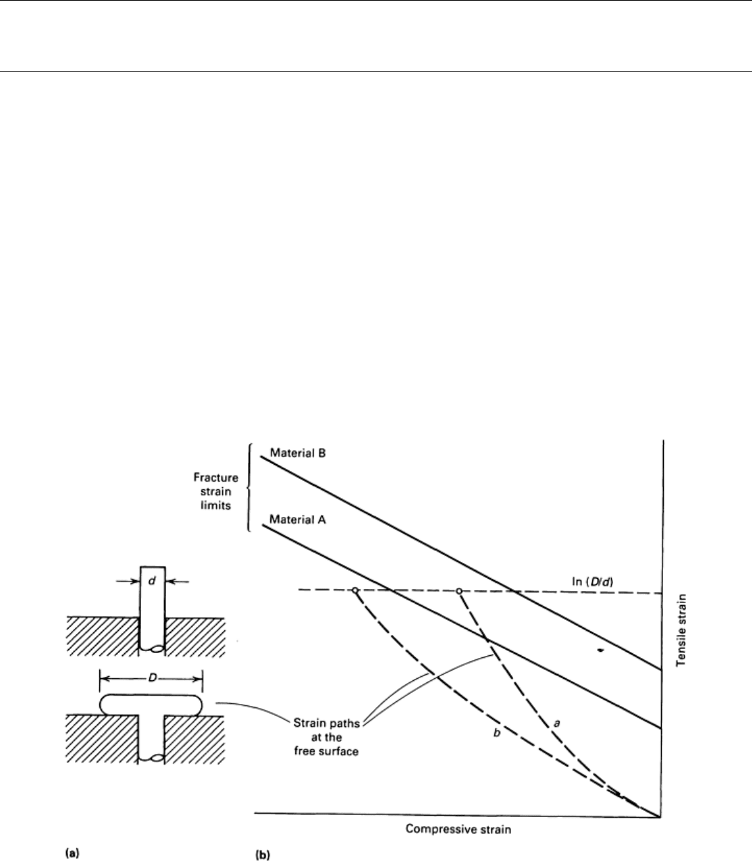
An example is the bolt-heading process shown in Fig. 24(a). If it is required to form a bolt head diameter D from the rod
of diameter d, the required circumferential strain is ln (D/d), indicated by the horizontal dashed line in Fig. 24(b). The
strain paths that reach this level, however, depend on process parameters, as shown previously in Fig. 2(b), and the
fracture strain loci vary with material, as shown in Fig. 10, 11, and 12. Referring to Fig. 24(b), if strain path a describes
the strain state at the expanding free surface for one set of processing conditions and the material used has a forming limit
line labeled A, then, in order to reach the required circumferential strain, the strain path must cross the fracture line, and
fracture is likely to occur. As shown, one option for avoiding defects is to use material B, which has a higher fracture
limit. Another option is to alter the process so that strain path b is followed by the material. The latter option represents a
process change, which in this case involves improved lubrication, as shown in Fig. 2. This procedure has been quantified
and implemented in a computerized tool for upsetting process design (Ref 13).
Fig. 24 Upsetting (a) of bar diameter d to head diameter D. (b) Material fracture strain limits are superimposed
on strain paths reaching the final required strain. Strain path b
(low friction) prevents fracture for both
materials. Material B avoids fracture for either strain path.
In more complex cases, other means are available for altering the strain path, such as modification of die design,
workpiece (preform) design, and redistribution of lubricant. Examples of application to powder forging preform design
and other metalworking processes are given in Ref 14 and 15.
The workability concept presented above provides a useful supplement to the experience and intuition of the die designer
because it presents a graphical and quantitative description of the relationship between material and process parameters.
Below are some examples of the application of the workability analysis procedures described previously.
Bar Rolling. As shown in Fig. 3, the strains at the edges of bars during rolling are similar to those at the bulging free
surface of a cylinder during compression. It should be possible, then, to predict fracture in bar rolling from compression
tests on the alloy of interest. This is pertinent in current attempts to roll ingots of high alloy content into bar form. The
complete workability study of bar rolling includes physical modeling of bar rolling to obtain the strain states at the edges
of the bar, compression tests to obtain the material fracture limits, and comparison of the two sets of results to establish
roll pass reduction limits.
Such a study is illustrated by the analysis of cracking during the rolling of 2024-T351 aluminum alloy bars. The intent
was to roll square bars into round wire without resolutioning. Rolling was done on a two-high reversible bar mill with 230
mm (9 in.) diam rolls at 30 rpm (approximate strain rate: 4 s
-1
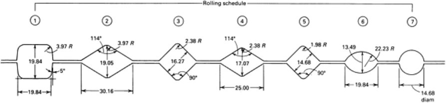
). The roll groove geometry is shown in Fig. 25. Defects
occurred primarily in the square-to-diamond passes (1-2 and 3-4), but the two diamond-to-square passes (2-3 and 4-5), the
square-to-oval pass (5-6), and the oval-to-round pass (6-7) were also examined for completeness.
Fig. 25 Roll groove geometry for rolling square bars into round wire. Dimensions given in millimeters.
Lead was used as the simulation material for the physical modeling of bar rolling. Pure (99.99%) lead was cast and
extruded into 25 mm (1 in.) round bars and then squared in the box pass (step 1, Fig. 25). Grids were placed on the lateral
edges of the bars by an impression tool, and the grid spacing was measured before and after each pass for calculation of
the longitudinal, ε
1
, and vertical, ε
2
, strains. Different reductions in area were achieved by feeding various bar sizes and by
changing roll separation distances. A transverse slice was cut from the bars after each pass for measurement of the cross-
sectional area and calculation of the reduction.
Results of the strain measurements are summarized in Fig. 26, in which tensile strain is plotted simultaneously with the
compressive strain and reduction. As expected, the square-to-diamond passes involve the least compressive vertical strain,
and the square-to-oval pass has the greatest compressive strain. The tensile strain versus reduction plot is the same for all
cases, reflecting volume constancy.
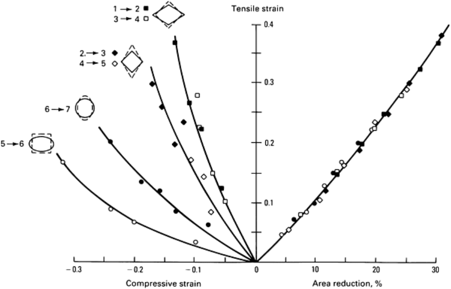
Fig. 26 Measured localized strains during the rolling of
lead bars. Left side shows longitudinal tensile strain
versus vertical compressive strain. Right side shows longitudinal strain versus cross-
sectional area reduction at
room temperature.
Compression tests were performed on the 2024 aluminum alloy at room temperature and at 250 °C (480 °F) at a strain
rate of 4 s
-1
to determine fracture limit lines. Straight, tapered, and flanged specimen profiles were used. Results are given
in Fig. 27. Superposition of Fig. 26 onto Fig. 27 gives the rolling deformation limits.
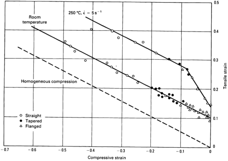
Fig. 27
Fracture strain lines for 2024 aluminum alloy in the T351 temper, measured by compression tests at
room temperature and at 250 °C (480 °F).
To test the workability predictions, aluminum alloy bars were rolled at room temperature and at 250 °C (480 °F). Grid
and area reduction measurements were made for the square-to-diamond passes. Figure 28 shows the measured strains at
room temperature, which agree with those measured in lead bars for the same pass (Fig. 26). Open circles indicate
fracture, and closed circles indicate no fracture. The fracture line for the aluminum alloy at room temperature is
superimposed as the dashed line. It is clear that edge cracking in bar rolling conformed with the material fracture line, and
the limiting reduction is approximately 13% for this combination of material and pass geometry. Similarly, at 250 °C (480
°F), there was conformance between fracture in bar rolling (Fig. 29) and the fracture line of the alloy (Fig. 28). In this
case, the limiting reduction is approximately 25%.
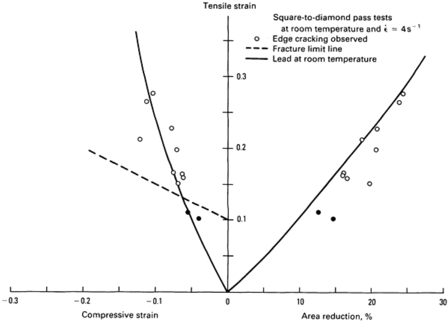
Fig. 28 Superposition of fracture line (dashed) on measured strains during rolling of 2024-
T351 aluminum alloy
bars at room temperature. Solid line represents the strain path measured during rolling of the lead model
material shown in Fig. 26.
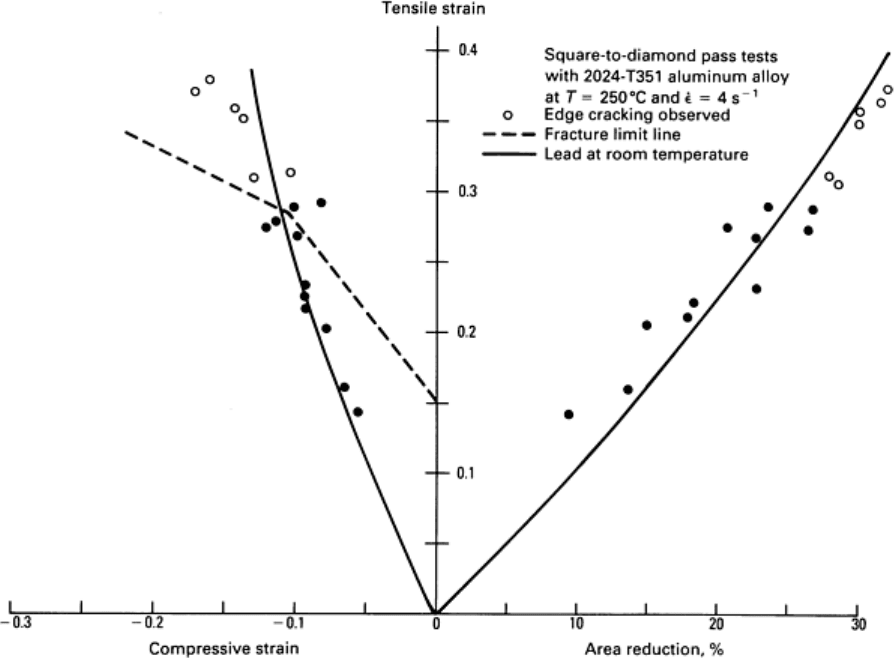
Fig. 29 Superposition of fracture line (dashed) on measured strains during the rolling of 2024-
T351 aluminum
alloy bars at 250 °C (480 °F). Solid line represents the strain path measured during rolling of the lead model
material shown in Fig. 26.
Extrapolating the above results for cold rolling, the limiting reduction for diamond-to-square passes would be
approximately 15%; for the oval-to-round pass, approximately 20%; and for the square-to-oval pass, approximately 25%.
Similarly, in the hot rolling of this aluminum alloy, the reduction limit for diamond-to-square passes would be
approximately 27%; for oval-to-round passes, approximately 30%; and for square-to-oval passes, approximately 40%.
The latter two are beyond the reduction normally used because of fin formation, so cracking rarely occurs in such passes.
Example 1: Preform Design for a Ball Bearing Race.
A low-load high-torque ball bearing outer race was cold forged from a low-alloy steel powder preform (Fig. 30). The
preforms were compacted from 4600 grade powder with carbon added to give 0.20% C in the sintered material. The
sintered preforms were 80% of theoretical density.
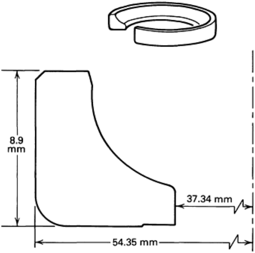
Fig. 30 Ball bearing outer race that was cold forged from sintered powder preform of 4620 low-alloy steel.
Initial efforts led to cracking through the preform along a diagonal beginning at the point of contact between the punch
and preform (Fig. 31). The large shear stress developed by the contact was beyond the fracture limit of the porous
preform, and two solutions were considered that would avoid such stresses (Fig. 32). The first solution was the use of a
flat preform that involves back extrusion flow into the outer rim, and the second was the use of a tall, thin-wall preform
that involves radial inward flow into the inner flange. The first option was rejected because it would generate
circumferential tension that would most likely cause fracture. The second option is desirable because compression is
applied at the top face; this option was pursued through physical modeling.
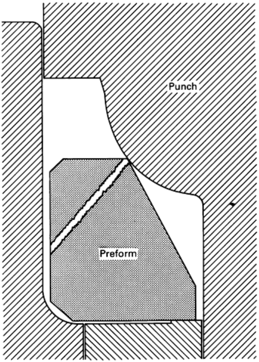
Fig. 31
Cracks initiated at the point of contact between the punch and preform in the original preform design.
The preform had a taper of 30° on the inside diameter.