ANSI/API Std 560: 2007 Fired Heaters for General Refinery Service (Eng)
Подождите немного. Документ загружается.

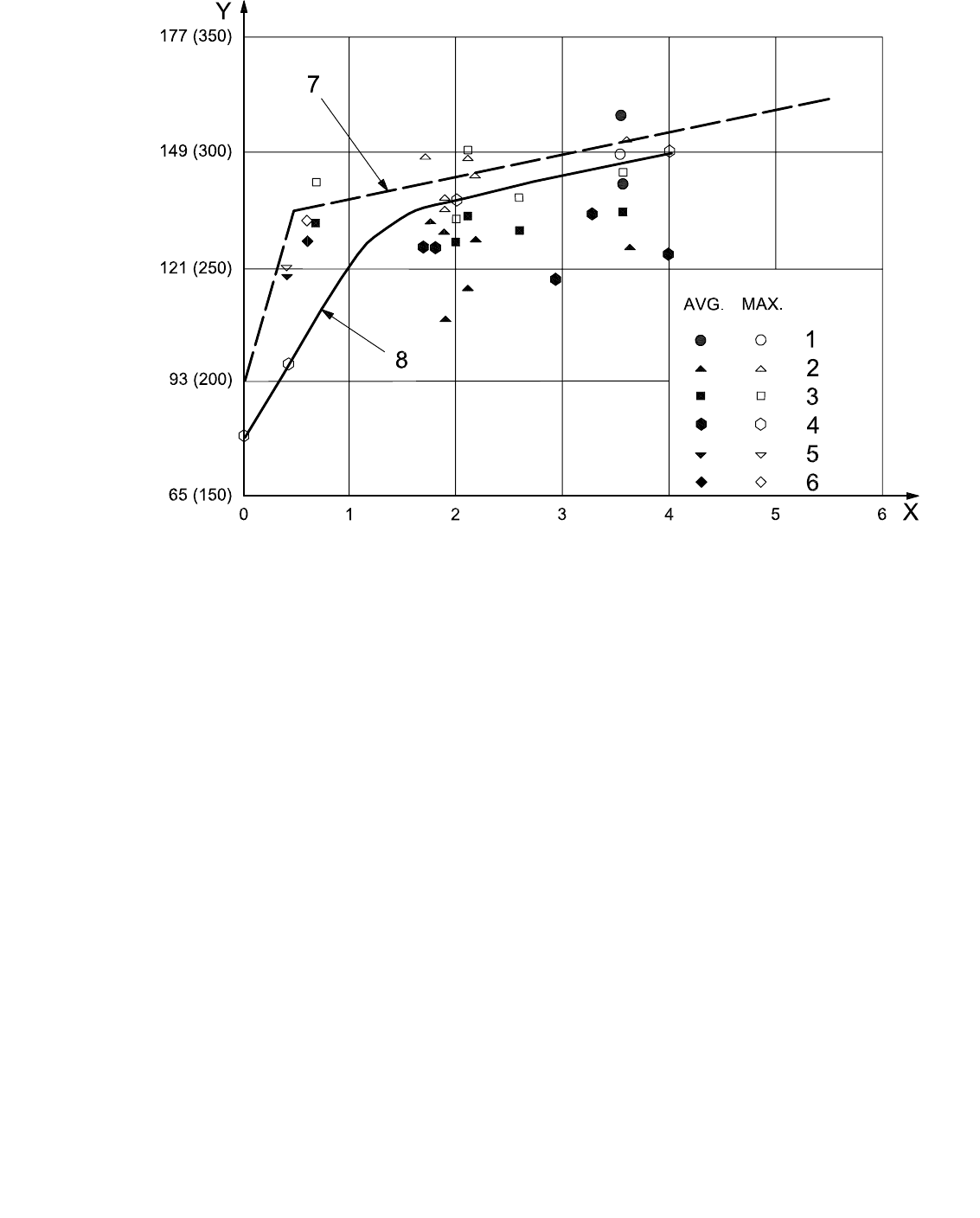
Key
X mass fraction of sulfur in fuel oil, expressed in percent
Y dew point, expressed in degrees Celsius (degrees Fahrenheit)
1 Draaijer and Pel
[34]
2 Bunz, Niepenberg and Rendle
[32]
3 Corbett
[28]
4 Clark and Childs
[31]
5 Martin (oil)
[36]
6 Martin (gas)
[36]
7 recommended minimum metal temperature for convection coils, fans and duct steel exposed to flue gas
8 Attig and Sedor
[35]
0,18 mm/y to 0,23 mm/y (7 mils/y to 9 mils/y) corrosion rate, 10 % excess air
Figure F.13 — Dew points of flue gas versus sulfur in fuel oil
(test data from industrial boilers and Reference [35])
ANSI/API Standard 560/ISO 13705
183
Copyright American Petroleum Institute
Provided by IHS under license with API
Licensee=TECNA/5935100001
Not for Resale, 09/06/2007 11:42:18 MDT
No reproduction or networking permitted without license from IHS
--```,``,`,`,```,``,,,,,,`,``-`-`,,`,,`,`,,`---
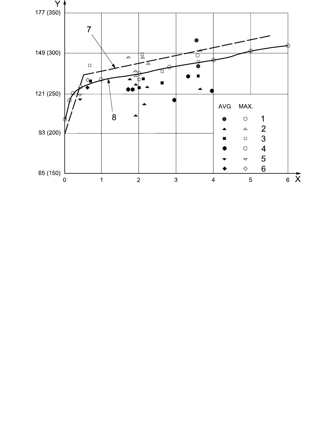
Key
X mass fraction of sulfur in fuel oil, expressed in percent
Y dew point, expressed in degrees Celsius (degrees Fahrenheit)
1 Draaijer and Pel
[34]
2 Bunz, Niepenberg and Rendle
[32]
3 Corbett
[28]
4 Clark and Childs
[31]
5 Martin (oil)
[36]
6 Martin (gas)
[36]
7 recommended minimum metal temperature for convection coils, fans and duct steel exposed to flue gas
8 Energy Technology, Inc., standards, 0,7 % to 3,5 % sulfur
Figure F.14 — Dew points of flue gas versus sulfur in fuel oil
(test data from industrial boilers and data of Energy Technology, Inc.)
F.12.7 Furnace cleanliness
In a commercial-size boiler fired with heavy fuel oil, Clark and Childs
[31]
report that the flue-gas dew point is
reduced by 17 °C (30 °F) after each annual furnace cleaning.
F.12.8 Burner design
In a laboratory combustor, Attig and Sedor
[35]
demonstrated that recirculation of 25 % of the flue gases to the
burners reduced flue-gas sulfur trioxide concentration by one half [equivalent to a dew-point reduction of at least
6 °C (10 °F)] and reduced corrosion rates by more than one third. The very low excess-air operations reported by
Bunz, Niepenberg and Rendle
[32]
were achieved with a special low-excess-air-design burner.
ANSI/API Standard 560/ISO 13705
184
Copyright American Petroleum Institute
Provided by IHS under license with API
Licensee=TECNA/5935100001
Not for Resale, 09/06/2007 11:42:18 MDT
No reproduction or networking permitted without license from IHS
--```,``,`,`,```,``,,,,,,`,``-`-`,,`,,`,`,,`---

Table F.4 — Flue-gas dew-point data from oil-fired industrial boilers
Dew point Sulfur
content in
fuel
Average Minimum Maximum
No. test
points
Steam load
Excess O
2
Investigator
Boiler
No.
% mass
fraction
°C (°F) °C (°F) °C (°F)
kg/h
× 1
000
%
1 3,55 158 (317) 157 (315) 159 (318) 4 40 — Draaijer and
Pel
[34]
2 3,55 142 (287) 134 (273) 149 (300) 15 9 to 14 —
3 1,78 132 (270) 121 (250) 147 (297) 8 24 and 32 0,1 to 0,5
3 1,90 129 (264) 118 (244) 138 (280) 6 24 and 32 0,1 to 1,5
4 2,10 116 (240) 74 (165) 147 (297) 10 24 and 32 0,1 to 1,5
4 2,18 127 (261) 86 (187) 143 (289) 10 24 and 32 0,1 to 1,5
4 1,90 108 (226) 75 (167) 135 (275) 8 24 and 32 0,1 to 1,4
Bunz,
Niepenberg
and
Rendle
[32]
4 3,61 127 (260) 70 (158) 152 (306) 16 16, 24 and 32 0,1 to 1,4
5 2,60 130 (266) 118 (245) 138 (280) 49 9 to 23 3,4 to 13,2
5 2,00 127 (260) 118 (245) 132 (270) 25 9 to 23 4,3 to 9,8
5 2,10 133 (271) 118 (243) 149 (300) 27 9 to 22 3,1 to 10,6
5 3,55 134 (274) 125 (257) 144 (292) 39 9 to 22 2,7 to 6,3
Corbett
[28]
5 0,75 131 (267) 121 (250) 141 (285) 22 13 to 18 3,6 to 8,2
6 3,97 125 (257) — — — — —
7 1,70 126 (258) — — — — —
8 1,82 126 (258) — — — — —
9 2,94 118 (245) — — — — —
Clark &
Childs
[31]
10 3,29 134 (274) — — — — —
11 (oil) 0,4
116 (240)
a
142 (287)
a
120 (248)
a
8 100 2,7 to 3,6
Martin
[36]
11 (gas) 0,6
127 (260)
a
122 (252)
a
131 (268)
a
15 100 2,5 to 3,3
a
Indirect measurements from SO
3
concentration. Electrical conductivity probe method would probably give lower values.
ANSI/API Standard 560/ISO 13705
185
Copyright American Petroleum Institute
Provided by IHS under license with API
Licensee=TECNA/5935100001
Not for Resale, 09/06/2007 11:42:18 MDT
No reproduction or networking permitted without license from IHS
--```,``,`,`,```,``,,,,,,`,``-`-`,,`,,`,`,,`---

Annex G
(informative)
Measurement of efficiency of fired-process heaters
G.1 General
G.1.1 Introduction
This annex is intended to establish a standard approach for measuring the thermal and fuel efficiency of
fired-process heaters. It comprises a comprehensive procedure for conducting the necessary tests and reporting
the results.
This procedure is intended to be used for fired heaters burning liquid or gaseous fuels. It is not recommended for
determining the thermal or fuel efficiency if a solid fuel is being burned.
The test procedure considers only stack heat loss, radiation heat loss and total heat input. Process data are
obtained for the purposes of reference and comparison only. Any modifications of the procedure and any
assumptions required for testing should be established before testing.
G.1.2 Terms, definitions and symbols
G.1.2.1 Terms and definitions
The following terms and definitions used in this annex are given for information.
G.1.2.1.1
thermal efficiency
total heat absorbed divided by total heat input
NOTE This definition differs from the traditional definition of fired heater efficiency, which generally refers to the fuel
efficiency.
G.1.2.1.2
fuel efficiency
total heat absorbed divided by the heat input derived from the combustion of the fuel only (h
L
)
G.1.2.1.3
total heat absorbed
total heat input minus total heat loss
G.1.2.1.4
total heat input
sum of net heat of combustion of the fuel (h
L
) and sensible heat of the air, fuel and atomizing medium
G.1.2.1.5
total heat loss
sum of radiation heat loss and stack heat loss
G.1.2.1.6
radiation heat loss
defined percentage of net heat of combustion of the fuel
ANSI/API Standard 560/ISO 13705
186
Copyright American Petroleum Institute
Provided by IHS under license with API
Licensee=TECNA/5935100001
Not for Resale, 09/06/2007 11:42:18 MDT
No reproduction or networking permitted without license from IHS
--```,``,`,`,```,``,,,,,,`,``-`-`,,`,,`,`,,`---

G.1.2.1.7
stack heat loss
total sensible heat of the flue-gas components at the temperature of flue gas when it leaves the last
heat-exchange surface
G.1.2.1.8
sensible heat correction
sensible heat differential at test temperatures when compared with a datum temperature of 15 ºC (60 ºF) for air,
fuel and the atomizing medium
NOTE With steam as an atomizing medium, the datum enthalpy is 2 530 kJ/kg (1 087,7
Btu/lb).
G.1.2.2 Symbols
The following symbols are used in this annex:
e net thermal efficiency, expressed as a percentage
e
f
fuel efficiency, expressed as a percentage
e
g
gross thermal efficiency, expressed as a percentage
h
L
lower massic heat value of the fuel burned, in J/kg (Btu/lb)
h
H
higher massic heat value of the fuel burned, in J/kg (Btu/lb)
c
p a
specific heat capacity of the air, in J/kg⋅K (Btu/lb⋅°F)
c
p f
specific heat capacity of the fuel, in J/kg⋅K (Btu/lb⋅°F)
c
p
m
specific heat capacity of the atomizing medium, in J/kg⋅K (Btu/lb⋅°F)
ΔE enthalpy difference
Δh
a
air sensible massic heat correction, in J/kg (Btu/lb)
Δh
f
fuel sensible massic heat correction, in J/kg (Btu/lb)
Δh
m
atomizing medium sensible massic heat correction, in J/kg (Btu/lb)
h
r
radiation massic heat loss, in J/kg (Btu/lb)
h
s
stack massic heat loss, in J/kg (Btu/lb)
m
a
mass of air, expressed in kilograms (pounds mass);
m
f
mass of the fuel, expressed in kilograms (pounds mass);
m
m
mass of the medium, expressed in kilograms (pounds mass);
m
st
mass of the steam, expressed in kilograms (pounds mass);
T
a
air temperature, in °C (°F)
T
a,a
ambient air temperature, in °C (°F)
T
d
design datum temperature, in °C (°F)
T
e
exit flue-gas temperature, in °C (°F)
T
f
fuel temperature, in °C (°F)
T
in
inlet coil temperature, in °C (°F)
T
m
atomizing-medium temperature, in °C (°F)
ANSI/API Standard 560/ISO 13705
187
Copyright American Petroleum Institute
Provided by IHS under license with API
Licensee=TECNA/5935100001
Not for Resale, 09/06/2007 11:42:18 MDT
No reproduction or networking permitted without license from IHS
--```,``,`,`,```,``,,,,,,`,``-`-`,,`,,`,`,,`---

G.1.3 Instrumentation
G.1.3.1 General
The instrumentation specified in G.1.3.2 and G.1.3.3 is required for the collection of data and the subsequent
calculations necessary to determine the thermal efficiency of a heater (see Figure G.1).
G.1.3.2 Temperature-measuring devices
A multi-shielded aspirating (high-velocity) thermocouple (see Figure G.2) shall be used to measure all
temperatures of the flue gas and temperatures of the preheated combustion-air above 260 °C (500 °F).
Thermocouples with thermowells may be used to measure temperatures at or below 260 °C (500 °F).
Conventional measuring devices may be used to measure the temperatures of the ambient air, the fuel and the
atomizing medium. For a discussion of conventional temperature measurements, refer to API RP 554.
ANSI/API Standard 560/ISO 13705
188
Copyright American Petroleum Institute
Provided by IHS under license with API
Licensee=TECNA/5935100001
Not for Resale, 09/06/2007 11:42:18 MDT
No reproduction or networking permitted without license from IHS
--```,``,`,`,```,``,,,,,,`,``-`-`,,`,,`,`,,`---
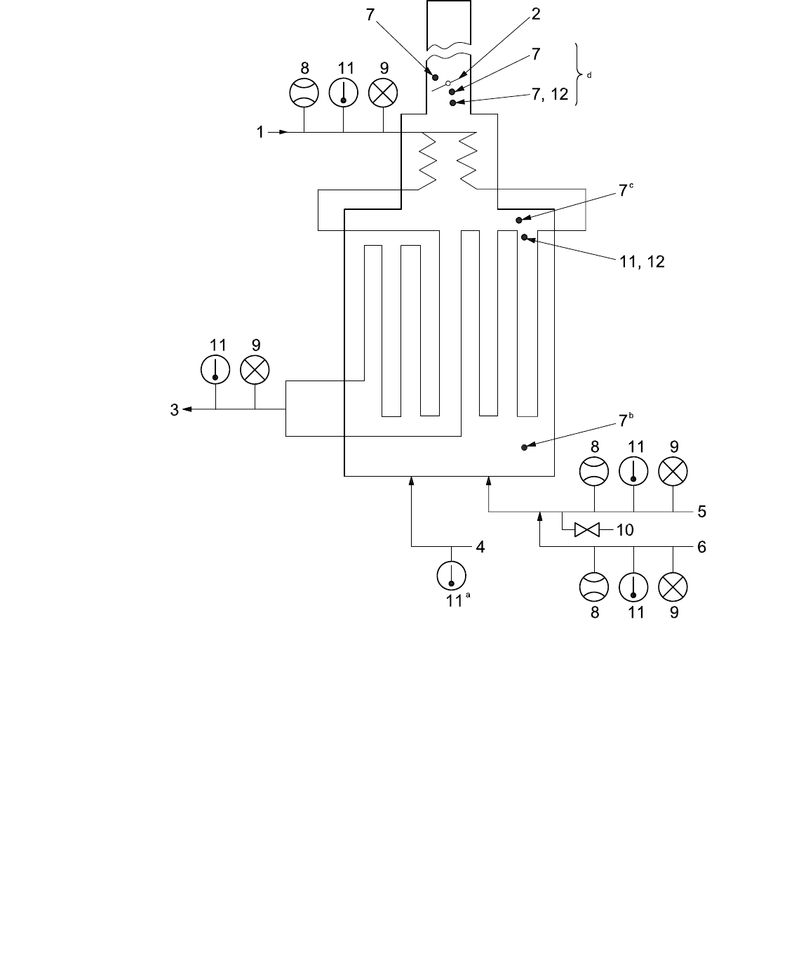
Key
1 feed in 5 fuel in 9 pressure indicator
2 damper 6 atomizing medium 10 sampling connection
3 feed out 7 draught gauge 11 temperature indicator
4 air in 8 flow indicator 12 oxygen sampling
a
Before preheater for internal heat source or after preheater for external heat source.
b
Near burners.
c
Arch.
d
After preheater for internal-heat-source system.
Figure G.1 — Instrument and measurement locations
ANSI/API Standard 560/ISO 13705
189
Copyright American Petroleum Institute
Provided by IHS under license with API
Licensee=TECNA/5935100001
Not for Resale, 09/06/2007 11:42:18 MDT
No reproduction or networking permitted without license from IHS
--```,``,`,`,```,``,,,,,,`,``-`-`,,`,,`,`,,`---
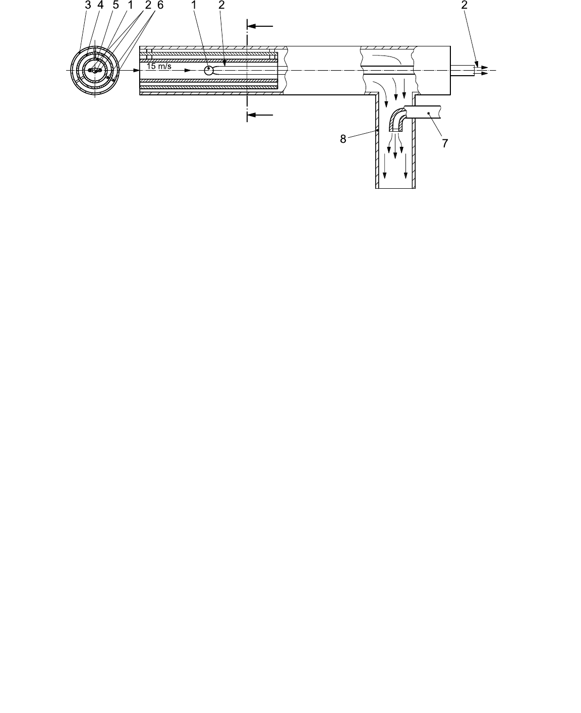
Key
1 thermocouple junction
2 thermocouple wires to temperature-indicating instrument
3 outer thin-wall 310 stainless steel tube
4 middle thin-wall 310 stainless steel tube
5 centre thin-wall 310 stainless steel tube
6 centring tripods
7 air or steam at 600 kPa [6 bar (ga)] or more, in increments of 600 kPa (6 bar) until stable
8 hot gas eductor
Figure G.2 — Typical aspirating (high-velocity) thermocouple
G.1.3.3 Flue-gas analytical devices
A portable or permanently installed analyser shall be used to analyse for oxygen and combustible gases in the
flue gas. The analysis of the flue gas may be made on either a wet or a dry basis, but the calculations shall be
consistent with the basis used. For a discussion of sampling systems and flue-gas analysers, refer to API RP 555.
G.1.4 Measurement
The following measurements shall be taken for reference purposes and for identification of heater operating
conditions. If more than one process service or auxiliary stream is present, the data should be taken for all
services.
a) fuel flow rate;
b) process flow rate;
c) process-fluid inlet temperature;
d) process-fluid outlet temperature;
e) process-fluid inlet pressure;
f) process-fluid outlet pressure;
g) fuel pressure at the burner;
h) atomizing-medium pressure at the burner;
i) flue-gas draught profile.
ANSI/API Standard 560/ISO 13705
190
Copyright American Petroleum Institute
Provided by IHS under license with API
Licensee=TECNA/5935100001
Not for Resale, 09/06/2007 11:42:18 MDT
No reproduction or networking permitted without license from IHS
--```,``,`,`,```,``,,,,,,`,``-`-`,,`,,`,`,,`---

G.2 Testing
G.2.1 Preparation for testing
G.2.1.1 The following ground rules shall be established in preparation for the test, prior to the date of the
actual test run:
a) operating conditions that will prevail during the test;
b) any re-rating that will be necessary to account for differences between the test conditions and the design
conditions;
c) acceptability of the fuel or fuels to be fired;
d) selection of instrumentation types, methods of measurement and specific measurement locations.
G.2.1.2 All instrumentation that will be used during the test shall be calibrated before the test.
G.2.1.3 Immediately before the actual test, the following items shall be verified:
a) that the fired process heater is operating at steady-state conditions;
b) that the fuel to be fired is acceptable;
c) that the heater is operating properly with respect to the size and shape of the flame, excess air, flue-gas
draught profile, cleanliness of the heating surfaces and balanced burner firing.
G.2.2 Testing
G.2.2.1 The heater shall be operated at a uniform rate throughout the test.
G.2.2.2 The test shall last for a minimum of 4 h. Data shall be taken at the start of the test and every 2 h
thereafter.
G.2.2.3 The duration of the test shall be extended until three consecutive sets of collected data fall within the
prescribed limits listed in Table G.1.
Table G.1 — Allowed variability of data measurements
Datum Limit
Heating value of fuel
± 5 %
Fuel rate
± 5 %
Flue-gas combustibles content
< 0,1 %
Flue-gas temperature
± 5 °C (9 °F)
Flue-gas oxygen content
± 1 %
Process flow rate
± 5 %
Process temperature in
± 5 °C (9 °F)
Process temperature out
± 5 °C (9 °F)
Process pressure out
± 5 %
ANSI/API Standard 560/ISO 13705
191
Copyright American Petroleum Institute
Provided by IHS under license with API
Licensee=TECNA/5935100001
Not for Resale, 09/06/2007 11:42:18 MDT
No reproduction or networking permitted without license from IHS
--```,``,`,`,```,``,,,,,,`,``-`-`,,`,,`,`,,`---

G.2.2.4 The data shall be collected as follows.
⎯ All of the data in each set shall be collected as quickly as possible, preferably within 30 min.
⎯ The quantity of fuel gas shall be measured and recorded for each set of data and a sample shall be taken
simultaneously for analysis.
⎯ For gaseous fuels, the net heating value shall be obtained by composition analysis and calculation.
⎯ The quantity of liquid fuel shall be measured and recorded for each set of data. It is necessary to take only
one sample for analysis during the test run.
⎯ For liquid fuels, the net heating value shall be obtained by calorimeter test. Liquid fuels shall also be analysed
to determine the hydrogen/carbon ratio, sulfur content, water content and the content of other components.
⎯ Flue-gas samples shall be analysed to determine the content of oxygen and combustibles. Samples shall be
taken downstream of the last heat-exchange (heat-absorbing) surface. If an air heater is used, samples shall
be taken after the air heater. The cross-sectional area shall be traversed to obtain representative samples. A
minimum of four samples shall be taken not more than 1 m (3 ft) apart.
⎯ The flue-gas temperature shall be measured at the same location used to extract samples of flue gas for
analysis. Systems designed to operate on natural draught upon loss of preheated air shall also measure the
flue-gas temperature above the stack damper. If the measured temperature reveals leakage (that is, if the
stack temperature is higher than the temperature at the exit from the air heater), then flue-gas samples shall
also be taken at this location to determine the correct overall thermal efficiency. The cross-sectional area
shall be traversed to obtain the representative temperature. A minimum of four measurements shall be taken
not more than 1 m (3 ft) apart.
G.2.2.5 The thermal efficiency shall be calculated from each set of valid data. The accepted final results are
then the arithmetic average of the calculated efficiencies.
G.2.2.6 All of the data shall be recorded on the standard forms presented in Clause G.4.
G.3 Determination of thermal and fuel efficiencies
G.3.1 Calculation of thermal and fuel efficiencies
G.3.1.1 Net thermal efficiency
Figures G.3, G.4 and G.5 illustrate heat inputs and heat losses for typical arrangements of fired-process heater
systems.
For the arrangements in Figures G.3, G.4 and G.5, the net thermal efficiency, e, (based on the lower heating value
of the fuel) is equal to the total heat absorbed times 100, divided by the total heat input. The total heat absorbed is
equal to the total heat input minus the total heat losses, so the net thermal efficiency, e, is given by
Equation (G.1):
Lafmrs
Lafm
( ΔΔΔ)( )
100
( ΔΔΔ)
hhhhhh
e
hhhh
+++ −+
=×
+++
(G.1)
where
e is the net thermal efficiency, expressed as a percentage;
h
L
is the lower massic heat value of the fuel burned, expressed in kJ/kg (Btu/lb);
Δh
a
is the air sensible massic heat correction, expressed in kJ/kg (Btu/lb)
ANSI/API Standard 560/ISO 13705
192
Copyright American Petroleum Institute
Provided by IHS under license with API
Licensee=TECNA/5935100001
Not for Resale, 09/06/2007 11:42:18 MDT
No reproduction or networking permitted without license from IHS
--```,``,`,`,```,``,,,,,,`,``-`-`,,`,,`,`,,`---