ANSI/API Std 560: 2007 Fired Heaters for General Refinery Service (Eng)
Подождите немного. Документ загружается.

The pressure drop, Δ
P
1,2
, in the run location 1 to 2, expressed in mm H
2
O (in H
2
O), is given by Equation (F.22) in
SI or USC units:
Δ
P
1,2
= C
r,1,2
(H
v,1
− H
v,2
) (F.22)
where
C
r,1,2
is the run-loss coefficient, from location 1 to 2, dimensionless;
NOTE A typical value is 0,50 for the net value of loss and regain, but this could be lower for a well-designed branch
connection.
H
v,1
and H
v,2
are the velocity heads at locations 1 and 2, respectively, expressed in mm H
2
O (in H
2
O).
The pressure drop, Δ
P
1,3
, into branch, location 1 to 3, expressed in mm H
2
O (in H
2
O), is given by Equation (F.23)
in SI or USC units:
Δ
P
1,3
= H
v,1
(C
b,1,3
− 1) + H
v,3
(F.23)
where
H
v,1
and H
v,3
are the velocity heads, at locations 1 and 3, respectively, expressed in mm H
2
O (in H
2
O);
C
b,1,3
is the branch loss coefficient (see Figures F.9 and F.10), from location 1 to 3, dimensionless.
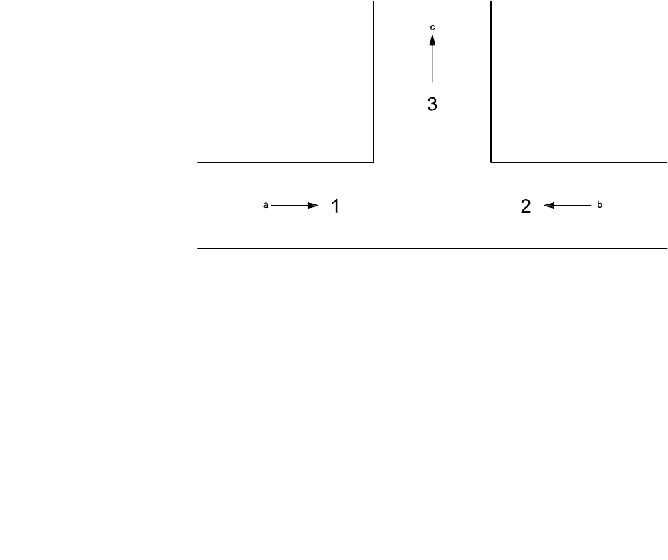
Key
1 inlet stream 1
2 inlet stream 2
3 combined stream in branch
a
v
1
or q
m,a,1
b
v
2
or q
m,a,2
c
v
3
or q
m,a,3
Figure F.9 — Location of pressure-measuring points 1, 2 and 3
ANSI/API Standard 560/ISO 13705
163
Copyright American Petroleum Institute
Provided by IHS under license with API
Licensee=TECNA/5935100001
Not for Resale, 09/06/2007 11:42:18 MDT
No reproduction or networking permitted without license from IHS
--```,``,`,`,```,``,,,,,,`,``-`-`,,`,,`,`,,`---

Key
X branch to main velocity ratio, v
3
/ v
1
Y branch loss coefficient,
C
b
, based on upstream main velocity
1 90° take-off
2 60° take-off
3 45° take-off
Figure F.10 — Branch loss coefficients
F.8.5 Differential pressure (draught) resulting from temperature differential
The draught or differential pressure, ΔP, calculated in SI units and expressed in mm H
2
O, is given by
Equation (F.24):
Δ
P = 0,120 3 × P
a
[(29/T
a
) − (M
r
/T
g
)] (l
2
− l
1
) (F.24)
ANSI/API Standard 560/ISO 13705
164
Copyright American Petroleum Institute
Provided by IHS under license with API
Licensee=TECNA/5935100001
Not for Resale, 09/06/2007 11:42:18 MDT
No reproduction or networking permitted without license from IHS
--```,``,`,`,```,``,,,,,,`,``-`-`,,`,,`,`,,`---

where
P
a
is the atmospheric absolute pressure at site grade, expressed in kilopascals;
T
a
is the absolute temperature of ambient air, expressed in kelvin;
T
g
is the temperature of flue gas or air in duct, expressed in kelvin;
M
r
is the relative molecular mass of the flue gas, expressed in kilograms per kilogram-mole;
l
1
is the elevation of point 1 above grade, expressed in metres;
l
2
is the elevation of point 2 above grade, expressed in metres.
The draught or differential pressure, Δ
P, calculated in USC units and expressed in in H
2
O, is given by
Equation (F.25):
Δ
P = 0,017 9 × P
a
[(29/T
a
) − (M
r
/T
g
)] (l
2
− l
1
) (F.25)
where
P
a
is the atmospheric absolute pressure at site grade, expressed in pounds per square inch;
T
a
is the absolute temperature of ambient air, expressed in degrees Rankine;
T
g
is the temperature of flue gas or air in duct, expressed in degrees Rankine;
M
r
is the relative molecular mass of the flue gas, expressed in pounds per pound-mole;
l
1
is the elevation of point 1 above grade, expressed in feet;
l
2
is the elevation of point 2 above grade, expressed in feet.
F.8.6 System zones
F.8.6.1 General
Regardless of which type of APH system is used, one or more of the duct zones shown in Figure F.11 is probably
involved. Knowledge of the basic flows, temperatures and pressure drops for equipment within the system and
knowledge of the basic spatial relationships of the components of the system are necessary for establishing
meaningful calculations.
The following are two common sources of error, which should be considered in the evaluation of the forced-and
induced-draught zones.
a) Because a small pressure differential exists across the stack-isolation damper, some cold-to-hot flue-gas
recycling occurs. Such flue-gas recycling reduces the effectiveness of the preheater and, if the amount is
large, it can overload the ID fan.
b) Similarly, because a small pressure differential exists between the air and flue-gas sides of a preheat
exchanger, air leakage into the flue-gas stream occurs in regenerative exchangers and can occur in most
recuperative exchangers. Typically, regenerative exchangers in good condition experience 5 % to 15 % air-
leakage rates. Leakage rates are higher if the exchanger is in need of maintenance. Recuperative
exchangers typically have less than 1,0 % leakage rates. If there is any air leakage across the air preheater,
it is necessary to add it to the cold flue-gas flow at this point to determine the induced-draught fan’s flow rate.
ANSI/API Standard 560/ISO 13705
165
Copyright American Petroleum Institute
Provided by IHS under license with API
Licensee=TECNA/5935100001
Not for Resale, 09/06/2007 11:42:18 MDT
No reproduction or networking permitted without license from IHS
--```,``,`,`,```,``,,,,,,`,``-`-`,,`,,`,`,,`---
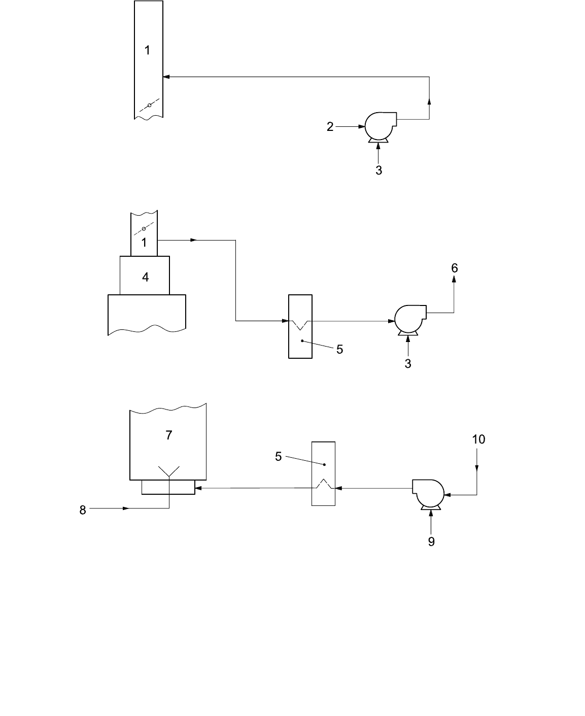
a) Typical induced-draught zone (induced-draught blower to top of stack)
b) Typical induced-draught zone (furnace to induced-draught blower)
c) Typical forced-air zone
Key
1 stack with damper 5 air preheater 8 fuel
2 from air preheater 6 to stack 9 forced-draught fan
3 induced-draught blower 7 furnace plenum 10 inlet trunk or silencer
4 furnace convection section
Figure F.11 — Duct zones
ANSI/API Standard 560/ISO 13705
166
Copyright American Petroleum Institute
Provided by IHS under license with API
Licensee=TECNA/5935100001
Not for Resale, 09/06/2007 11:42:18 MDT
No reproduction or networking permitted without license from IHS
--```,``,`,`,```,``,,,,,,`,``-`-`,,`,,`,`,,`---

F.8.6.2 Forced-draught zone
The forced-draught zone usually consists of the following: inlet stack, suction ducting, forced-draught fan, cold-air
ducting, preheater, hot-air ducting, burner plenum and burners. Using the ends of this zone (e.g. the burner
discharge and suction-stack inlet) as the anchor points, the operating pressure profile within the FD zone can be
described as follows.
a) The pressure at the burner discharge, inside the fired heater, is the draught at the floor (i.e. the arch draught
plus the radiant-section draught). It is necessary to add the pressure drop across the burner to this floor-
draught pressure (whether it be negative or positive) to obtain the burner-plenum or burner-duct pressure.
b) If appropriate, the pressure losses of the feeder ducts (i.e. branch connections) should be added to the
burner plenum pressure to arrive at the hot-combustion-air-duct terminus pressure.
c) As appropriate, the pressure losses of the hot-combustion-air ducting should be added to the hot-air-duct
terminus pressure to arrive at the preheater’s hot-air outlet pressure.
d) As appropriate, an allowance should be made for any dampers and/or flow-measurement devices in the hot-
combustion-air ducting.
e) The preheater’s air-side pressure drop should be added to the preheater’s outlet pressure to arrive at the
preheater’s inlet pressure.
f) The pressure losses of the fan-discharge ducting should be added to the preheater’s inlet pressure to arrive
at a FD-fan discharge pressure.
g) The pressure losses through the suction stack, silencer and suction ducting should be subtracted from the
atmospheric pressure to obtain the FD-fan’s suction pressure.
h) By definition, the FD-fan’s static pressure rise is the FD-fan’s discharge pressure minus its suction pressure.
Clearly, the above overview is conceptual and the pressure profile of each zone requires a specific analysis that
accounts for the unique features of the system.
F.8.6.3 Induced-draught zone
The elements in this zone are typically the following: the convection section, uptake ducts, stack breeching, lower-
stack section, isolation damper, hot-flue-gas ducting, air preheater, suction ducting, induced-draught fan, cold-
flue-gas ducting and stack. All pressures upstream of the ID fan are increasingly negative. Pressures downstream
of the ID-fan should be slightly positive (i.e. above atmospheric pressure). Using the ends of this zone (e.g. the
arch and ID-fan inlet flange) as the anchor points, the operating-pressure profile within the ID zone can be
described as follows.
a) The gauge pressure at the arch is typically specified to be − 2,5 mm H
2
O (− 0,10 in H
2
O).
b) The pressure drop of the convection section, and any supplemental heat-recovery coils, should be subtracted
from the arch pressure to arrive at the breeching pressure.
c) The pressure drop of the stack transition, uptake ducts and stack plenum (as appropriate) should be
subtracted from the breeching pressure to arrive at the stack-base pressure.
d) The pressure losses of the lower stack, hot-flue ducts and preheater inlet transition should be subtracted from
the stack-base pressure to arrive at the preheater inlet pressure.
e) The pressure drop of the preheater should be subtracted from the inlet pressure to arrive at the preheater
outlet pressure.
f) The pressure drop of the preheater-outlet transition and suction ducting should be subtracted from the
preheater outlet pressure to obtain the ID-fan suction pressure.
ANSI/API Standard 560/ISO 13705
167
Copyright American Petroleum Institute
Provided by IHS under license with API
Licensee=TECNA/5935100001
Not for Resale, 09/06/2007 11:42:18 MDT
No reproduction or networking permitted without license from IHS
--```,``,`,`,```,``,,,,,,`,``-`-`,,`,,`,`,,`---

F.8.6.4 Flue-gas-return zone (induced-draught fan to top of stack)
The elements in this zone are the induced-draught fan, the cold-flue-gas ducting and the upper stack. It should be
noted that a separate stack can be utilized so that the flue gas is not returned to the original stack. Using the ends
of this zone (e.g. the stack-discharge point and ID-fan inlet flange) as the anchor points, the operating pressure
profile within this zone can be described as follows.
a) The pressure drop of the upper stack, cold-flue-gas ducting and the ID-fan discharge ducting should be
added to atmospheric pressure to arrive at the ID-fan’s discharge pressure.
b) By definition, the ID-fan’s static pressure rise is the ID-fan’s discharge pressure minus its suction pressure.
F.8.7 Draught effects
Even though they are commonly considered during stack-draught calculations, draught effects are present for any
system involving both a temperature differential (internal temperature vs. ambient temperature) and changes in
elevation. This draught effect can produce either positive or negative pressure changes depending on elevation
changes and conditions. All duct calculations should account for the differential pressures resulting from
temperature differences, commonly known as draught effect. Draught effects should be accounted for in
determining net pressure losses or gains in any system.
Refer to F.8.5 for the recommended methodology that may be used to calculate draught effect.
F.8.8 Dual-draught systems
In those systems with burners intended to be operated on natural draught as well as in the forced- or
induced-draught mode, the sizing and arranging of ducts, plenums and air-door components must accommodate
both types of operations. It is necessary that the heater’s draught be adequate to overcome the friction losses of
the system between the burner and the atmosphere. To facilitate swift conversion to natural draught, it is common
practice to provide “natural-draught air doors” on, or adjacent to, the burner plenum. These doors fail open as
appropriate to provide a local source of ambient combustion air for the heater.
F.8.9 Additional references
References [39] to [43] provide additional information.
F.9 Major-components design guidelines
F.9.1 Introduction
Clause F.9 covers the design and fabrication of the various APH-system components that are not covered
elsewhere within this International Standard. The preferred choice of materials, where applicable, is also included.
F.9.2 Ductwork
F.9.2.1 General
The ductwork requirements for APH systems can be separated into two classifications: flue-gas ductwork and
combustion-air ductwork. The mechanical and structural design principles are the same for both. General
recommended design requirements are the following.
a) Design and fabrication should comply with this International Standard.
b) Ducts should be gas-tight.
ANSI/API Standard 560/ISO 13705
168
Copyright American Petroleum Institute
Provided by IHS under license with API
Licensee=TECNA/5935100001
Not for Resale, 09/06/2007 11:42:18 MDT
No reproduction or networking permitted without license from IHS
--```,``,`,`,```,``,,,,,,`,``-`-`,,`,,`,`,,`---

c) Field joints should be flange-and-gasket or seal-welded construction.
d) Ductwork should permit replacement of components (e.g. dampers, blowers, heat exchangers and expansion
joints).
e) Ductwork should provide uniform fluid flow distribution into the APH exchanger.
Failure to achieve a uniform velocity distribution can reduce the performance of preheaters and fans. Internal duct
bracing, if used, should not be installed within three diameters of equipment since disruption or restriction of the
flow can occur. Use of turning vanes or straightening vanes should be considered to ensure uniform distribution.
F.9.2.2 Cross-section
The choice of cylindrical or rectangular duct designs is based on packaging (i.e. physical shape requirements)
and economics. Where space permits, round sections of ducts are recommended because of the following.
a) Round ducting provides the maximum flow area per unit of duct mass.
b) Round ducting is structurally stronger than rectangular ductwork of the same mass.
c) Round ducting generally requires less material for structural support.
d) Round ducting is less prone to resonating with the induced harmonics.
Rectangular ducts shall be reinforced in a manner that keeps the deflections and stresses within acceptable limits.
Also, the designer should avoid having the flat side of ducts coincidently resonant with blower or fan speeds.
Designing for possible buckling of flat walls can require additional bracing for stiffness.
F.9.2.3 Layout and routing considerations
The following are recommended ductwork layout and routing guidelines.
a) All flue-gas ducts that tie into a heater stack should have a structural anchor (on the duct) close to the stack
tie-in point. An expansion joint should be located between the fixed point (i.e. anchor) and the stack to
minimize the duct thermal-expansion forces and the resultant significant bending moment.
b) A single stack is recommended for “common” APH systems that service multiple heaters.
c) Manually adjustable and lockable biasing dampers should be provided in all applications that have parallel air
ducts connected to a common header. Each parallel air duct should have its own biasing damper to provide a
means for adjusting the airflow in each duct.
d) All duct sections should be equipped with low-point drain connections. These connections should be at least
DN 40 (NPS 1
1/2) nominal size.
e) Manways should be a minimum of (460 × 460) mm [(18 × 18) in] and so located in the ductwork (if size
permits) to provide for internal access to the entire duct system.
f) Vertical, self-supporting cylindrical ducts should be designed as stacks. They should be designed to safely
withstand wind loads and wind-induced (vortex-shedding) vibrations as specified in 13.5.
g) Structural force should not be imposed on expansion joints.
h) Expansion provisions for lined ducts should be based on the calculated casing temperature plus 55 °C
(100 °F).
ANSI/API Standard 560/ISO 13705
169
Copyright American Petroleum Institute
Provided by IHS under license with API
Licensee=TECNA/5935100001
Not for Resale, 09/06/2007 11:42:18 MDT
No reproduction or networking permitted without license from IHS
--```,``,`,`,```,``,,,,,,`,``-`-`,,`,,`,`,,`---

F.9.2.4 Mechanical design
F.9.2.4.1 Design pressure
Ductwork should be structurally designed for the maximum expected shut-in pressure of the fan or the differential
pressure (i.e. the maximum operating pressure minus the ambient pressure), whichever is greater, but not less
than 3,4 kPa (0,5 psig). If the design defaults to 3,4 kPa (0,5 psig) design pressure, it should be assumed that the
fluid pressure is positive within the duct. Flat surfaces on the rectangular ductwork, if operating at less than
atmospheric pressure inside the duct, shall be designed for the expected vacuum.
F.9.2.4.2 Design loads
Ducts and supports should be designed to accommodate all thermal and mechanical loads that can be imposed,
including erection (including the mass of wet refractory during start-up, operation or shutdown of the system).
Where duct sections can be removed for maintenance activities, the effect of existing loads and new forces
results in changes of deflection or stress; the entire system design shall again be mechanically verified in
accordance with codes or procedures agreed to by the user and the vendor. The loads and thermal effects of
cold-weather design conditions (i.e. snow and ice) during shutdowns should also be considered in the analysis of
ductwork. Additional reinforcement can be required for transient conditions or resonant fan conditions.
F.9.2.4.3 Thermal expansion
All ductwork subject to thermal expansion should be analyzed for thermal stresses encountered at the design
pressure and design metal temperature. All ductwork subject to thermal expansion shall have supports designed
to freely accommodate the expected movement resulting from thermal effects or to accept the forces and
stresses. The use of rollers, graphite slides or polytetrafluoroethylene slide plates can be required to prevent
binding of support shoes.
F.9.2.5 Combustion air plenums
The plenum design and layout should be such that there is a clearance around and under the plenum to permit
withdrawal of burner parts without dismantling the plenum. The plenum should not enclose the structural supports
of the fired process heater without providing for structural integrity. Plenum design should be such that the
process-heater floor structure does not fail in the event of a fire in the plenum.
In retrofit situations, the design of floor support beams in the existing process heater shall be verified during the
design for the effects of preheated air on structural integrity. Separate insulated plenum boxes can be required.
The use of air spaces between main structural supports and preheated air plenums should be considered during
the design.
F.9.3 Expansion joints
F.9.3.1 General
All ductwork subject to thermal expansion shall be furnished with metallic-bellows or flexible-fabric-bellows
expansion joints suitable for gas temperatures expected in the ductwork and resistant to any corrosion products in
the gas stream. Internal sleeve liners to protect the bellows of the expansion joint should be considered. Stiffening
rings may be installed on either end of expansion joints in the ductwork to prevent ovalling of the ductwork or
other distortion of the ductwork in the event of replacement of the expansion joint.
All ducts having expansion joints at both ends shall be suitably anchored or restrained between the joints to
ensure absorption of ductwork thermal growth in the expansion joints in the desired manner.
If duct thermal expansion is deliberately controlled to cause lateral deflection in the expansion joint, the expansion
joint shall be specified and designed to absorb lateral deflection or angulation without overstressing the bellows
material at design temperature. Expansion joints subject only to lateral deflection should be provided with tie rods
ANSI/API Standard 560/ISO 13705
170
Copyright American Petroleum Institute
Provided by IHS under license with API
Licensee=TECNA/5935100001
Not for Resale, 09/06/2007 11:42:18 MDT
No reproduction or networking permitted without license from IHS
--```,``,`,`,```,``,,,,,,`,``-`-`,,`,,`,`,,`---

across the bellows. The tie-rod connections to the duct work shall be gimballed to allow lateral displacement in the
expansion joint without bending or shearing the tie rods or tie-rod connections. Do not use a tied expansion joint
to absorb both axial and lateral deflections. Only internal pressure thrusts are contained by tie rods.
F.9.3.2 Fabric expansion joints
Flexible fabric joints should be used to avoid stressing and/or deforming adjoining equipment. These expansion
joints are usually a layered construction of materials suitable for the design conditions. If fabric expansion joints
are used adjacent to components requiring steam cleaning or water washing, the use of internal sleeves is
recommended to prevent water damage to the fabric joint.
F.9.3.3 Metallic slip joints
Packed slip expansion joints can be a suitable alternative to fabric joints for negative-pressure applications. These
slip joints should be designed to provide positive retention of the packing and permit packing replacement from
the outside while the duct is in service. These joints should be between solid anchor points in hot ductwork.
Slip joints are subject to binding because of dirt, paint or corrosion. Avoid using slip joints adjacent to blower/ fan
inlet or outlet flanges. Slide bars or guide pins should be provided to prevent angulation (i.e. cocking) in the gland
when friction or stresses within the gland is/are inconsistent around the joint circumference. Packed expansion
joints can be designed to take horizontal movements if used as two hinged joints.
F.9.4 Dampers
F.9.4.1 Overview
In any duct-system design, the selection and location of the system’s dampers should consider safety,
maintenance, process and control needs and requirements. In short, each damper application has its own unique
set of requirements. Table F.3 provides recommended damper types for the common APH-system applications.
When selecting a damper, the following should be considered:
a) design pressure and design differential pressure;
b) design temperature;
c) design leakage rate;
d) application type, as discussed below;
e) mode of operation (manual, automatic, etc.);
f) materials of construction of blades, shafts, bearings, frame, etc.;
g) rate of operation;
h) local instrumentation (limit switches, positioners, etc.).
Dampers can be classified into four types, based upon the amount of internal leakage across the closed damper
at operating pressures:
⎯ tight shutoff: low leakage;
⎯ isolation or guillotine (slide gate): no leakage;
⎯ flow control or distribution: medium to high leakage;
⎯ natural-draught air-inlet doors: low leakage to full open.
ANSI/API Standard 560/ISO 13705
171
Copyright American Petroleum Institute
Provided by IHS under license with API
Licensee=TECNA/5935100001
Not for Resale, 09/06/2007 11:42:18 MDT
No reproduction or networking permitted without license from IHS
--```,``,`,`,```,``,,,,,,`,``-`-`,,`,,`,`,,`---

Tight shutoff dampers may be of single blade or multi-blade construction. Leakage rates of 0,5 % or less of flow at
operating conditions are typical.
Guillotine blinds or slide gates are used to isolate equipment, either after a change to natural draught or when
isolating one of several heaters served by a common preheat system. The design should consider exposure of
personnel, the effects of leakage on heater operation, the tightness of damper shutoff and the location of the
damper (close to or remote from the affected heater). Isolation or guillotine (slide gate) dampers are designed to
have no internal leakage when closed and may include double-gate with air purge or double-block-and-bleed
designs consisting of one or more dampers in series with an air purge between. Internal leakage rates of 0 % are
expected with this type of damper. Guillotines may have insulated blades to allow personnel to safely enter
ductwork (downstream of the damper) during operation of connected equipment. Refer to F.9.4.3 for further
guidelines.
Flow-control dampers are typically multiple-louvre, opposed-acting, multiple-blade dampers because such
dampers have superior flow-control capabilities. Parallel-blade or single-blade dampers should not be applied
where the flow-directing feature inherent in their design can impair fan performance or provide an unbalanced flow
distribution in the preheater. Actuation linkage for dampers used for control or tight shutoff should have a
minimum number of parallel or series arms. The potential for asymmetrical blade movement and leakage
increases with linkage complexity.
Natural-draught air doors shall be designed as fail-open devices in the event of loss of mechanical draught
provided by combustion-air fan. Natural-draught air doors should be sized and located in the ductwork such that
combustion-air flow to the burners during natural-draught operations is symmetrical and unrestricted. The
expected leakage or the leakage to be tolerated shall be stated in specifying damper requirements. With the
exception of isolation-damper designs, the amount of leakage varies with type and operating conditions.
Table F.3 — Recommended damper types
Equipment Function Recommended damper type
Forced-draught
Inlet Control Radial-vane damper, blade louvre or inlet box damper
Outlet Isolation for personnel safety Zero-leakage slide gate or guillotine blind
Outlet Control Multi-blade louvre
Induced-draught
Inlet Control Radial-vane damper, multi-blade louvre or inlet box damper
Inlet Isolation for personnel safety Zero-leakage slide gate or guillotine blind
Outlet Isolation for personnel safety Zero-leakage slide gate or guillotine blind
Stack Quick response, isolation and
control
Multi-blade louvre or butterfly damper
Combustion-air bypass Quick response, isolation and
control
Multi-blade louvre or butterfly damper
Emergency natural
draught/air inlet
Quick response and isolation Low-leakage damper or door
Fired heater Burner control Multi-blade or butterfly damper
Isolation Zero-leakage slide gate or guillotine blind
ANSI/API Standard 560/ISO 13705
172
Copyright American Petroleum Institute
Provided by IHS under license with API
Licensee=TECNA/5935100001
Not for Resale, 09/06/2007 11:42:18 MDT
No reproduction or networking permitted without license from IHS
--```,``,`,`,```,``,,,,,,`,``-`-`,,`,,`,`,,`---