Angermann L. (ed.). Numerical Simulations - Applications, Examples and Theory
Подождите немного. Документ загружается.

Applications of the Electrohydraulic Servomechanisms in Management of Water Resources
451
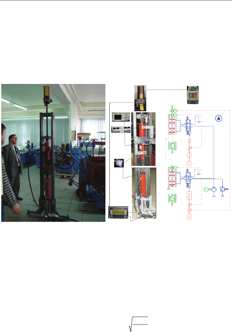
The TOPCON electronic block receives electric signal from the laser receiver, placed on the
rod of the upper cylinder of the device. The signal size varies depending on the level of
detection of the optical reference plane, generated by the rotary laser transmitter; the input
sent to the proportional valve of the TOPCON hydraulic kit is proportional with the
detection level. According to this prompt the rod of the bottom cylinder pulls or pushes the
body of the upper cylinder in reverse direction to that of deplacement of the cylinder rod.
The upper cylinder is controlled in close loop by means of a servocontroller; a signal
generator simulates various profiles for the uneven land. The two inductive transducers of
linear deplacement of the cylinders are connected by means of a data acquisition board to a
PC using TEST POINT DAS.
a) b)
Fig. 6. Test bench for testing the TOPCON laser controlled modular system: a) general
overview; b) the test bench versus AMESIM simulation model
4. Basic mathematical model of the test bench components
A deep understanding of the upper phisical performance needs at least a mathematical
modeling and simulation of an electro hydraulic servomechanism.
The simplest nonlinear realistic mathematical model of such a system contains the following
equations (Vasiliu &Vasiliu, 2005):
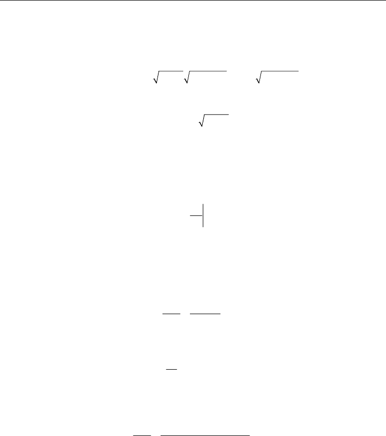
a. The steady-state characteristics of the servovalve main stage (four way, critical centre,
spool valve):
()
()
S
SV d
p
P
QxpcAx,
ρ
−
= (1)
Numerical Simulations - Applications, Examples and Theory
452
Here x is the spool displacement from the neutral position; P - pressure difference
between the ports of the hydraulic cylinder; A(x) – metering ports surface; c
d
–
discharge coefficient of the metering ports; p
S
- supply pressure (a constant). The above
relation can be written in the form
()
SV d s S S Qx S
QxPcdx
p
P
p
Kx P
p
,/1/1/
πρ
=−=− (2)
where
Qx d s S
Kcdp/
π
ρ
= (3)
is the "flow valve gain".
b.
The spool motion equation. The servovalves manufacturers specify for each device the
transfer functions adequate to slow, normal and high-speed control process. For slow
control process, the servovalve can be regarded as a proportional device, having a
single constant - the displacement-current (voltage) gain:
xi
x
x
K
i
0
∂
∂
=
=
(4)
Hence the spool motion follows the input current, i without any lag:
xi
xKi=
(5)
For normal control process, a servovalve can be regarded as a first order lag device:
(
)
()
xi
SV
xs
K
is T s 1
=
+
(6)
The corresponding differential equation is:
()
SV xi
dx
TxKit
dt
+=
(7)
Here T
SV
is the servovalve time constant. For high speed control process, we have to
consider the servovalve as a second order lag device:
(
)
()
()
xi
nn
xs
K
is
ss
2
/2/1
ωζω
=
++
(8)
where
n
ω
is the natural frequency and
ζ
- damping coefficient.
c.
The position transducer equation. The modern inductive position transducers together
with their amplifiers behave as first order lag devices; they have a very small time
constant, which can be neglected for industrial electro hydraulic control process:
TT
UKy= (9)
where
K
T
is the transducer constant, and y – piston displacement from the null position.

Applications of the Electrohydraulic Servomechanisms in Management of Water Resources
453
d. The error compensator equation. This stage computes the following error, ε as a
difference between the input signal, U
i
and the position transducer output, U
T
, and
applies the PID control algorithm to find the solenoid control voltage, U
c
:
U
c
(s) = ε(s)K
P
[1+1/(sT
i
) + sT
d
/(τs + 1)] (10)
e.
The servocontroller current generator equation. The current generator of the servo-
controller is so fast than it can be regarded as a proportional device:
C
i
iKU
=
(11)
where
i
K
[A/V] is the "medium" conversion factor.
f.
The continuity equation. This equation offers the connection between the servovalve
flow and the derivative of the pressure drop across the hydraulic cylinder:
p
SV p l
h
A
QAyKP P
R
2
=++
(12)
where A
p
is the piston area; K
l
- leakage coefficient between the motor chambers; R
h
-
hydraulic stiffness of the motor:
2
2
e
hp
t
RA
ε
=
V
(13)
Here
e
ε
is the equivalent bulk modulus of the oil and
t
V
- the total volume of the oil
from the hydraulic motor and the connections.
g.
The piston motion equation. The pressure force F
p
has to cover the load force, usually
modelled by a spring force F
e
, the inertia of all the moving parts, m
e
and the friction
force, F
f
with different components:
epef
my F F F
=
−−
(14)
where
pp
FAP
=
(15)
(
)
(
)
(
)
eee e e e
FKK
yy
K
yy
12 01 0
22=+ += + (16)
The friction force has mainly a static component, F
fs
and a viscous one, F
fv
:
fs fs
FFsi
g
n
y
0
=
(17)
f
v
f
v
FK
y
=
(18)
The main non-linearity in the above mathematical modeling is included in the
servovalve main stage. A linear solution can be obtained using a linear form of the
steady-state characteristics of the servovalve main stage,
SV Qx QP
QKxKP
=
− (19)
Numerical Simulations - Applications, Examples and Theory
454
The results supplied by the linear model are useful for estimating the stability only. For high
amplitude input signals the designer has to use the numerical simulation. Some simulation
languages are widely used for practical purposes. Two of them are available for any
engineering activity: SIMULINK (The Math Works Inc., 2007) and AMESIM (LMS Imagine,
2009). The „building“ of a simulation network in SIMULINK needs a lot of work for using
general purpose „icons“, but the toolboxes devoted to sistems synthesis are very effective.
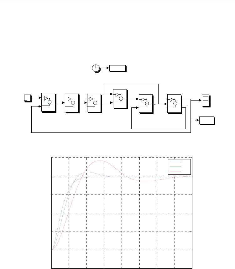
The fig. 7 contains the simulation network of the above electro hydraulic servomechanism.
Valve spool
motion equation
simout
To Workspace1
t
To Workspace
Piston stroke
Piston motion
equation
Input signal Uo
Flow equation
Error computation
block
Current gen.
equation
Control valve
characteristics
Clock
Fig. 7. Simulation network of an electro hydraulic servomechanism in SIMULINK
0 0.05 0.1 0.15 0.2 0.25 0.3 0.35 0.4
-0.005
0
0.005
0.01
0.015
0.02
0.025
t[s]
y[m]
0.01
0.02
0.05
Fig. 8. Small input step response of an electro hydraulic servomechanism simulated by
SIMULINK for three values of T
SV
: 0.01 s, 0.02 s, and 0.05 s
Figure 8 presents the response of the servomechanism for small step inputs, and three
values of the servovalve time constant, T
SV
. Using a high speeed servovalve one can obtain
an overall small time constant of about 0.045 s. The increase of the servovalve time constant
spoils the system dynamic performance and can generate steady state oscillations. A long
series of experiments were performed by (Calinoiu, Vasiliu & Vasiliu, 1998) in order to find
Applications of the Electrohydraulic Servomechanisms in Management of Water Resources
455
the difference between the theoretical dynamic behaviour and the real one for a
servomechanism using a Bosch NG10 direct drive servovalve (DDV). There is a good
agreement between the simulated and measured results, the time constant having
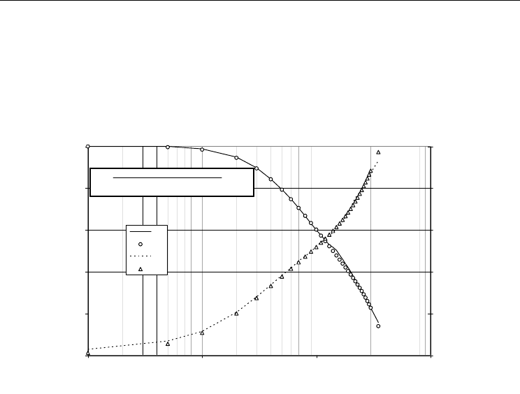
practically the same value for both cases. The Bode diagram (fig. 9) shows a good dynamics
even for a high spring load. On the same diagram the transfer function identified by
IDENTIFICATION TOOLBOX from MATLAB is specified. The computed transfer function
and the measured one are nearly the same.
-25.00
-20.00
-15.00
-10.00
-5.00
0.00
0.10 1.00 10.00 100.00
F[Hz]
A[dB]
0.00
35.00
70.00
105.00
140.00
175.00
[grade]
Am
Ac
Fm
Fc
Hs
ss s
()
,
=
+⋅+ ⋅+
1105000
286 1 58330 1085000
32
Fig. 9. Bode diagram of an electro hydraulic servomechanism (identification by MATLAB)
The simulation model of the test bench can be assemblied by two SIMULINK models as in
fig. 7, but the capabilities of AMESIM are very useful for the quick design and optimization.
5. AMESIM design facilities
5.1 Overview
Many different modeling and simulation software packages were created to perform studies
in the fields of automobile, aerospace, robotics, offshore and general hydraulics engineering
but none offered the full range of capabilities needed. There were deficiencies in the
numerical capabilities, in the graphical interface and in the general modeling concept. The
AMESim package was developed to overcome these limitations by Michel Lebrun and
Claude Richards from Societe Imagine (FRANCE), starting from 1988. This section gives a
description of the technical features, which were central objectives in the design of the
software, and some examples of typical applications.
The main aim of the AMESim is “To create Good Models without Writing a Single Line of
Code” (Lebrun & Richards, 1997). An important prerequisite of the basic element library is
the creation of extremely well tested, reliable and reusable submodels that a user can
employ with complete confidence (LMS IMAGINE SA, 2009). The writer of the basic
element library must be competent in all the modeling skills. However, the user of the basic
element library is relieved of the need to write code and formulate the mathematics.
Understanding of the details of the physics is not needed but decision on assumption is

Numerical Simulations - Applications, Examples and Theory
456
necessary which imply some knowledge of physics. Understanding of the engineering
system and an ability to interpret results is still important. Experience in training design
office staff to use of the basic element library suggests that it is learnt very rapidly.
AMESim is using the multiport approach. In the signal port approach of a numerical
simulation environment, a single value or an array of values are transferred from one
component block to another in a single direction. This is fine when the physical engineering
system behaves in the same way such as with a control system. However, problems arise
when power is transmitted. This is because modeling of components that transmit power
leads to a requirement to exchange information between components in both directions. In
order to use a signal port approach in this situation, two connections must be made between
the components where physically there is only one. This leads to a great complexity of
connections and means that even very simple models involving power transmission appear
complex and unnatural. In contrast to the signal port approach, with the multiport
approach, a connection between two components allows information to flow in both
directions. This makes the system diagram much closer to the physical system.
5.2 Numerical performance
The analysis of the steady state and dynamic behavior of an engineering system leads to a
mathematical model of the system. This is in the form of algebraic, ordinary differential and
partial differential equations. More recently, differentialalgebraic equations are also used to
model the system. The role of simulation software is to provide an environment in which
this model can be solved efficiently. For models with large numbers of partial differential
equations, there are specialist packages such as those for computation fluid dynamics. Such
software is used for detailed analysis of individual components of a system. However, it is
often necessary to simulate a completely engineering system or a subsystem of it. The
concept of the virtual prototype, in which physical prototypes are replaced by mathematical
computer models, makes simulation of this type vital. In this case, it is normal to reduce any
partial differential equations to ordinary differential equations. This leads to models with
either ordinary differential equations (odes) or differential algebraic equations (daes). Many
general and specialized simulation software packages are available for solving such systems
of equations. Models arising from engineering systems vary greatly in their character. Thus
the equations of the model can be: linear, non-linear, numerically stiff i.e. with very small
time constants compared with the overall simulation period, oscillatory, continuous,
discontinuous. A large variety of numerical integration methods can be employed to solve
such problems. Traditionally the user of simulation software is presented with a menu of
typically seven methods from which a choice must be made.
5.3 Direct access graphical user interface
Many older simulation packages were developed before modern graphical user interfaces
were available. The only graphical facilities provided were for producing simple plots of
results. The suppliers of these packages have had to introduce new graphical preprocessing
facilities to build the system. More modern software has been designed from the start with a
full graphical user interface. Whenever possible, icons for components were based on
internationally recognized standard symbols. Thus for hydraulic systems icons are based on
CETOPS symbols. Where there are no such standardized symbols, icons are constructed
which can be instantly recognized by engineers working in the field.
Applications of the Electrohydraulic Servomechanisms in Management of Water Resources
457
Throughout the simulation, process the system diagram is displayed. Thus for example
when parameters are changed for a particular component, the user points at the icon in
question and clicks the mouse button. This produces a menu of items that may be changed.
Similarly to plot graphs of results, the user points at the component and clicks the mouse
button to produce a menu of items associated with the component that may be plotted.
The possibility of quick high level technical developments as ABS, EBS, common rail
multipoint injection systems, electro hydraulic automatic transmissions, self tuning
hydraulic and pneumatic suspensions, hydraulic power steering, fly-by-wire systems and
many others (Mare & Cregut, 2001). Companies like AEROSPATIALE, MATRA, BOSCH,
FERRARI, DAIMLER-CRIYSLER, GENERAL MOTORS, etc. are currently using this
modeling and simulation software for future developments. Academic training programs
are now developed in different countries, for teaching the software in the terminal years
(Vasiliu & Vasiliu, 2005), and for applied researches (Vasiliu, et al., 2003).
6. Numerical simulation and experimental identification of the laser
controlled modular system by AMESim
6.1 Modelling the test bench
For the numerical simulation of the laser controlled modular system it was used the
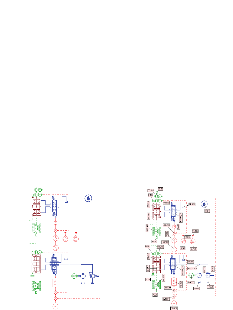
simulation in AMESim, namely the model shown in fig.10. All the components of the
simulation model are based on mathematical models of differential equations, validated by
practice and the method of numeric integration of the differential equations is chosen
automatically. If the model is not correct or the inner and outer parameters are not properly
determined, the program does not work, cause the system of differential equations is
incompatible or undetermined.
a)
b)
Fig. 10. Model of simulation in AMESim for a TOPCON laser controlled modular system
mounted on a testing device: a) simulation model; b) model components
Numerical Simulations - Applications, Examples and Theory
458
The simulation model represents an electrohydraulic servomechanism for adjusting the
position with laser reaction. It includes 2 inner adjustment loops and an outer loop. The first
inner loop is set at the level of the hydraulic servomechanism of simulation for uneven land
which is excited at entry with rectangular, sinusoidal signals, constant and variable. The
second inner loop is set at the level of the servomechanism of monitoring with laser control
which is similar to the TOPCON laser controlled modular system. The outer loop of
regulation is done between the exit of the first servomechanism and the entry of the second.
6.2 Numerical simulation experiments
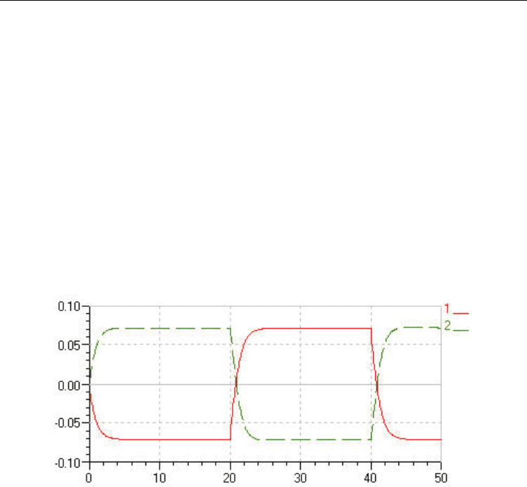
In fig.11…17 are shown some of the significant numeric simulations. In fig.11 the
servomechanism generating profiles of the uneven land receives a rectangular input with an
amplitude of 0,14 m and a frequency of 0,05 Hz in a range of 50 s. The red curve 1 represents
the desplacement of the rod of the generator servocylinder [m], and the green curve 2
represents the rod deplacement of the monitoring servocylinder rod and the body of the
generator servocylinder [m].
Fig. 11. The answer of the laser monitoring servomechanism at exciting the servomechanism
which generates profile with rectangular signal
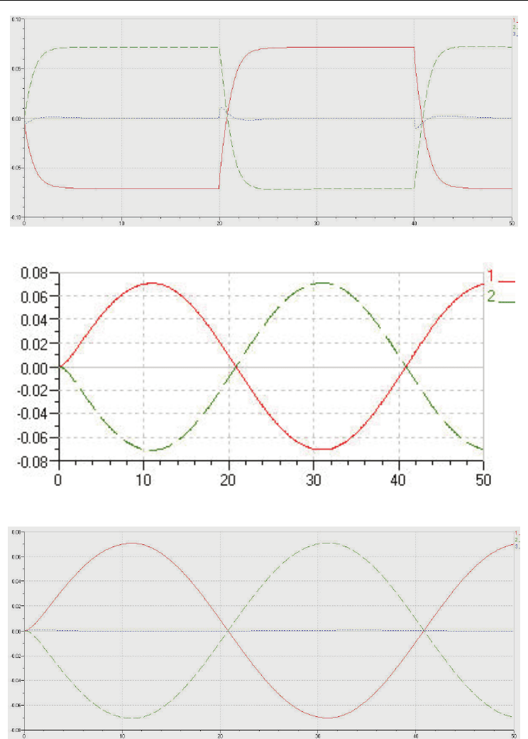
By the algebraic sum of the graphics from fig.11 results the curve 3 from fig.12. In the
terminology related to the operation of automatic land leveling after an horizontal plane
curve 3 represents the deviations of the profile of the levelled land from the optical
horizontal reference plane. These are present only in the zone of stage jumping last 2 s and
have a max.value of 0,01 m.
In fig.13 the servomechanism generating the profile of uneven land is excited with a
constant sinusoidal signal with an amplitude of 0,14 m and a frequency of 0,05 Hz lasting 50
s. The meaning of the curves 1 and 2 is the same with that from fig.11.
By the algebraic sum of the graphics from fig.13 it results the curve 3 from fig.14 with the
same meaning as that from fig.12. The errors are negligible with max.values below 0,002 m.
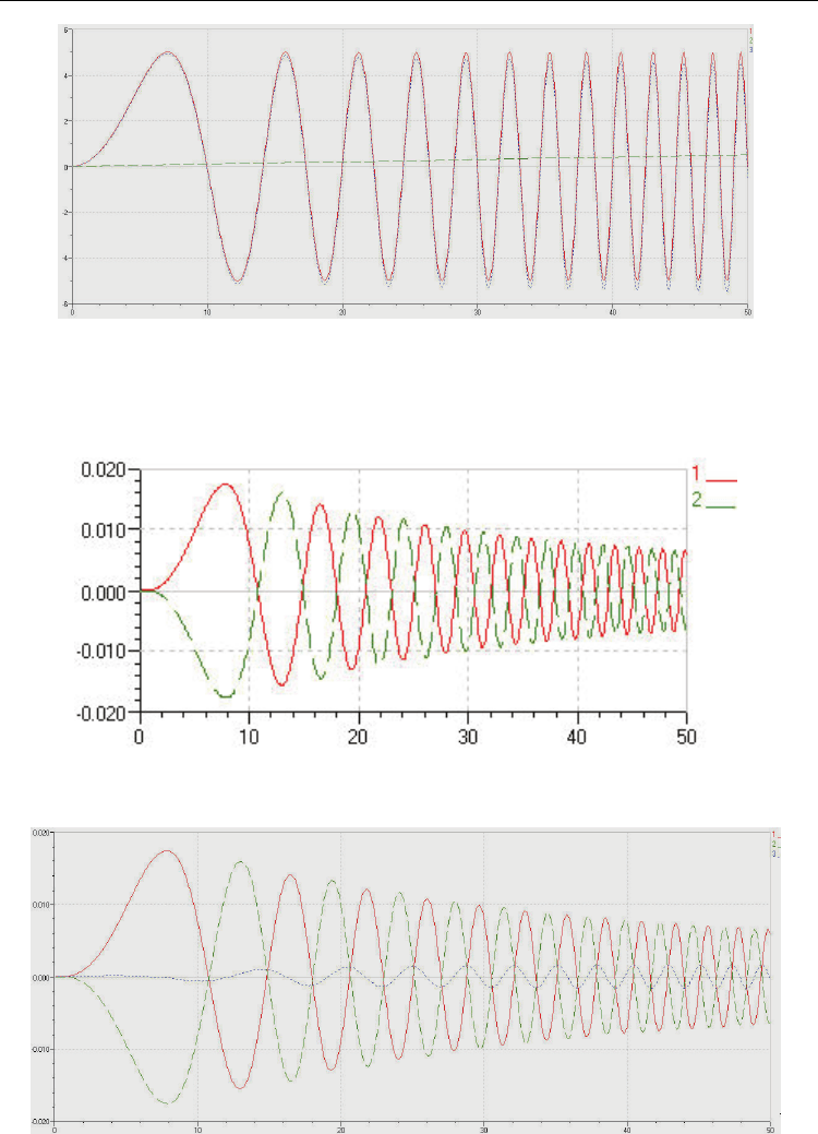
In fig.15. is shown a method for emitting in AMESim a sinusoidal signal with variable
amplitude and frequency: over the sinusoidal signal with variable frequency and constant
amplitude is superposed a ramp signal after this the 2 signals being composed. For the
component signals there is a model in AMESim but for the composed signal not.
Applications of the Electrohydraulic Servomechanisms in Management of Water Resources
459
Fig. 12. Deviation profile of the leveled land from the optical reference plane
Fig. 13. The answer of the laser monitoring mechanism for a constant sinusoidal input
Fig. 14. Deviation profile leveled land from the optical reference plane
Numerical Simulations - Applications, Examples and Theory
460
Fig. 15. The formation of a sinusoidal imput signal with variable frequency and amplitude
The meaning of the curves from fig.15. is the following: 1- sinusoidal signal with variable
frequency, max. frequency 0,5 Hz and amplitude 0,1 m; 2 – ramp signal; 3- sinusoidal signal
with variable frequency and amplitude.
Fig. 16. The answer of the laser monitoring servomechanism at exciting the servomechanism
generator of profile with variable sinusoidal signal
Fig. 17. Deviation leveled land profile from the optical reference plane
