Angermann L. (ed.). Numerical Simulations - Applications, Examples and Theory
Подождите немного. Документ загружается.

Numerical Simulation - a Design Tool for Electro Hydraulic Servo Systems
431
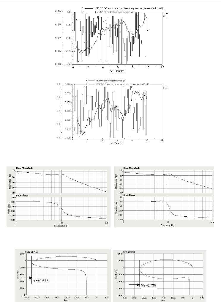
a) with constant area gradient
b) with variable area gradient
Fig. 5. Response over time of the servo mechanism to control signal of type white noise
a) with constant area gradient b) with variable area gradient
Fig. 6. Bode diagram of the servo mechanism in open loop
a) with constant area gradient b) with variable area gradient
Fig. 7. Hodograph of open-loop system
Numerical Simulations - Applications, Examples and Theory
432
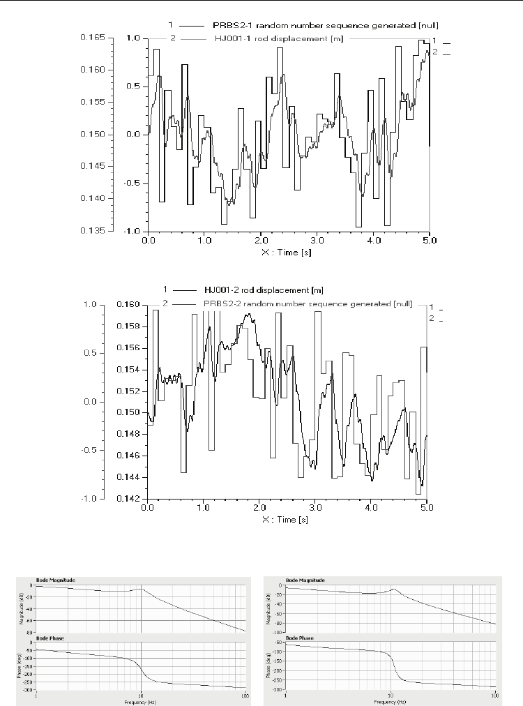
a) with constant area gradient
b) with variable area gradient
Fig. 8. Response over time of system in loop of response to control signal of type white noise
a) with constant area gradient b) with variable area gradient
Fig. 9. Bode diagram of the servo mechanism in closed loop

Numerical Simulation - a Design Tool for Electro Hydraulic Servo Systems
433
Discret mathematical models identified for closed-loop system with: (a) – directional control
valve without variable area gradient, (b)- directional control valve with variable area
gradient:
(a)
(b)
3. Optimization of hydrostatic transmissions by means of virtual
instrumentation technique
3.1 Problem formulation
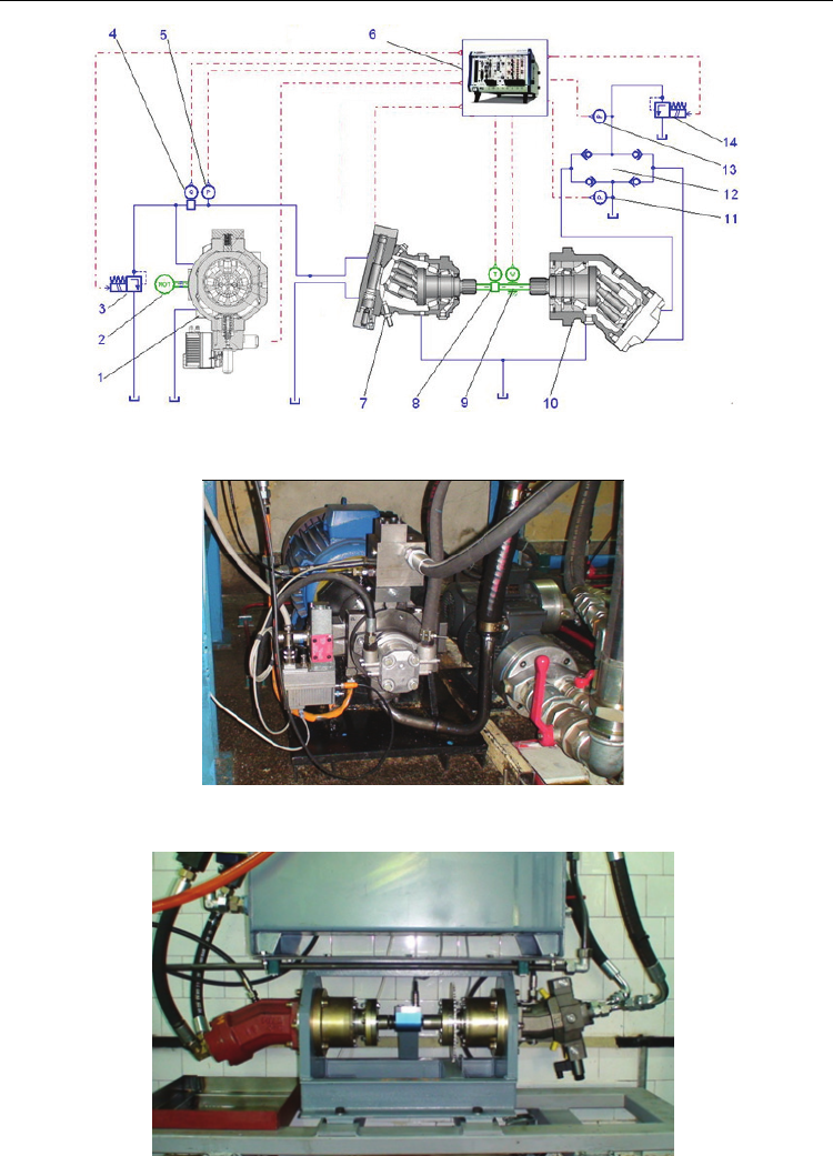
The analyzed hydrostatic transmission, of mixed adjustment, with single consumer of type
adjustable rotary volumetric motor, according to the basic model in fig.10, includes:
-
in its primary sector: a MOOG servopump, place 1, with radial pistons and integrated
electronics, with three loops of adjustment, that is in flow, in pressure, in flow and
pressure, with capacity of 32 cm
3
/rev, rotary speed of 1450 rev/min, control voltage of
0...10V, flow of 0...46 l/min; an electric motor for servopump actuation, of constant
rotary speed, place 2; a pressure limiting valve, place 3; a flow transducer, place 4; and a
pressure transducer, place 5.
-
in its secodary sector: a BOSCH servo motor type EP2, place 7, with axial pistons, tilted
block and integrated electronics, with minimum capacity of 7 cm
3
/rev at control
voltage of 200 mA and maximum capacity of 28 cm
3
/rev at control voltage of 800 mA,
at supply voltage of 24Vd.c.; a torque transducer place 8; a speed transducer, place 9;
an axial piston pump, with tilted block and fixed capacity place 10, to simulate the load
of hydraulic servo motor; two pressure transducers, place 11 and place 13; four way-
valves, place 12, fitted on suction / repression side of load pump; a pressure adjustment
valve, with electric control, place 14, for adjusting load of hydraulic servo motor.
-
a PXI-NATIONAL INSTRUMENTS block, place 6, which provides a virtual interface of
the adjustment process of capacity of the adjustable volumetric machines (LabVIEW /
PXI).
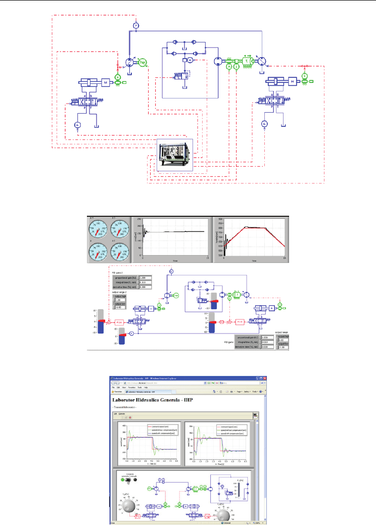
For this hydrostatic transmission we have developed a physical laboratory model,
according to fig.11 and fig.12; a numerical simulation network in AMESim, according to
fig.13; a virtual interface for the adjustment model of transmission, according to fig.14
and a web interface for the adjustment model of transmission, according to fig.15.
By means of the adjustment model of hydrostatic transmission with mixed adjustment the
following items were highlighted:
-
by means of co-simulation AMESim-LabVIEW: demonstration, on the physical
laboratory model, of primary (pump), secondary (motor) and mixed (pump and motor)
adjustments, specific to hydrostatic transmissions (Popescu et al., 2010); demonstration,
on the physical laboratory model, of the advantages, in terms of energy, of hydrostatic
transmissions with adjustable pumps in their primary sector over those with fixed
pumps in their primary sector (b. Drumea et al., 2010).
-
by means of simulation models in AMESim: optimization of the adjustment model of
a hydrostatic transmission with mixed adjustment in order to reduce variation of the
rotary speed of volumetric motor within its secondary sector, in accordance with
variation of its load.
Numerical Simulations - Applications, Examples and Theory
434
Fig. 10. Basic model of a hydrostatic transmission with mixed adjustment
Fig. 11. MOOG servopump, type RKP-D, within the primary sector
Fig. 12. Bosch servo motor, type EP2, within the secondary sector
Numerical Simulation - a Design Tool for Electro Hydraulic Servo Systems
435
Fig. 13. Simulation network in AMESim of a hydrostatic transmission with mixed
adjustment
Fig. 14. Virtual interface of the adjustment model (LabVIEW / PXI)
Fig. 15. Web interface of the adjustment model (LabVIEW / PXI)
Numerical Simulations - Applications, Examples and Theory
436
3.2 Demonstration of adjustment of capacity at adjustable volumetric machines
We have traced the response of the adjustment system of transmission, that actuates upon
the servomechanism which adjusts the capacity of the pump within the primary sector or
upon the servomechanism which adjusts the capacity of the motor within the secondary
sector, to rotational speed step type signal imposed to the volumetric motor within the
secondary sector. Within the adjustment model we have preset the rotational speed
threshold of 320 r.p.m, below which the adjustment of transmission is performed upon the
pump (primary adjustment) and above which the adjustment of transmission is performed
upon the motor (secondary adjustment).
Dynamic characteristics of the system were raised, which highlight:
-
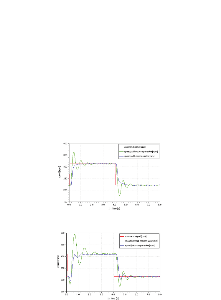
the influence of a rotational speed step type signal of 312 rpm imposed to the hydraulic
motor within the secondary sector, upon the adjustment drive of capacity of the
adjustable pump, with and without erorr compensation, according to fig.16;
-
the influence of a rotational speed step type signal of 410 rpm imposed to the hydraulic
motor within the secondary sector, upon the adjustment drive of capacity of the
adjustable pump, with and without erorr compensation, according to fig.17;
-
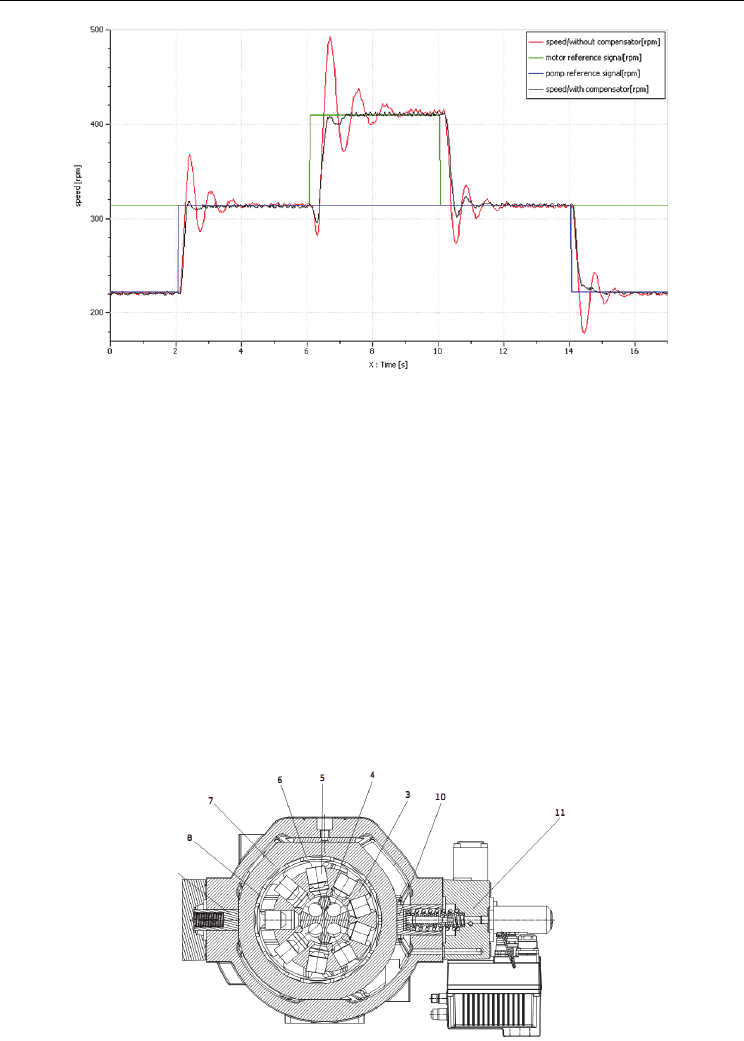
the influence of rotational speed step type mixed signals of 308 rpm, respectively 408
rpm, imposed to the adjustable hydraulic motor within the secondary sector, upon the
adjustment drive of capacity of the adjustable pump, respectively of the adjustable
motor, with and without erorr compensation, according to fig.18.
Fig. 16. Response of the adjustment system of rotational speed of hydraulic motor to step
type excitation signal – pump capacity drive
Fig. 17. Response of the adjustment system of rotational speed of hydraulic motor to step
type excitation signal – motor capacity drive
Numerical Simulation - a Design Tool for Electro Hydraulic Servo Systems
437
Fig. 18. Response of the adjustment system of rotational speed of hydraulic motor to mixed
step type excitation signal – pump and motor capacity drive
3.3 Numerical simulation of radial piston pump MOOG type RKP-D
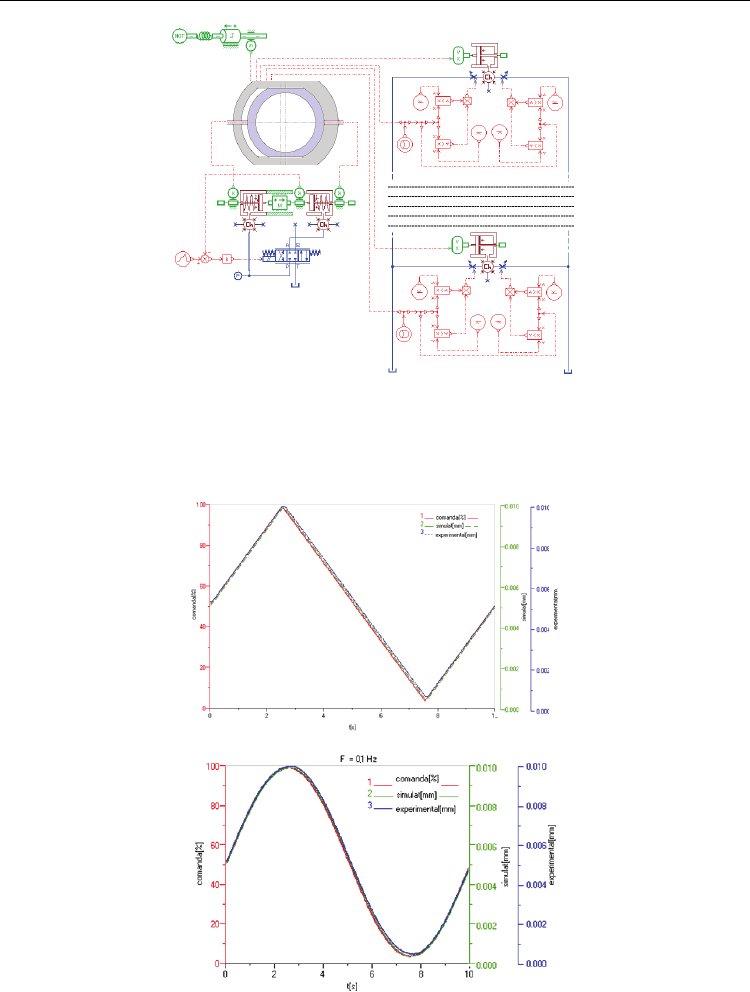
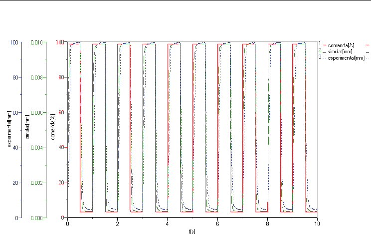
Simulation model developed for the analysis of volumetric pump in fig.19, is shown in
fig.20 (a. Drumea et al., 2010). It includes: the hydraulic servomechanism for prescribing the
position of the adjustment ring; a module for calculating the relative position of small
pistons as against to their angular position and the ordered eccentricity; the two small radial
pistons of the pump; the distribution unit, controlled by the angular position of small
pistons and the geometrical characteristics of the distribution flange.
By means of the modeling network developed, dynamic characteristics of the servo motor
that adjusts capacity of the analyzed radial piston pump were determined, figures 5 and 6.
The model was excited with control signals (prescribing of eccentricity of the flow
adjustment / control ring), triangular, sinusoidal and rectangular signals, of various
amplitudes and frequencies. Obtained results are compared, simulated and experimentally
shown. Simulation model has been "tuned" as a result of the comparative analysis between
simulated and experimental response for a better accuracy of results (Popescu et al., 2010).
Fig. 19. Servo pump MOOG type RKP-D; cross-section
Numerical Simulations - Applications, Examples and Theory
438
Fig. 20. Servo pump MOOG type RKP –D; numerical simulation model
In figures 21 and 22 curve 1 represents the control signal, curve 2 - response of
servomechanism that adjusts capacity, obtained through numerical simulation, and curve 3 -
response of servomechanism that adjusts capacity, obtained on an experimental basis.
a)
b)
Fig. 21. Response of the adjustment servomechanism to control triangular, (a) and
sinusoidal, (b) signals (f=0.1 Hz)
Numerical Simulation - a Design Tool for Electro Hydraulic Servo Systems
439
Fig. 22. Response of the adjustment servomechanism to a control rectangular signal (f=1 Hz)
3.4 Demonstration of advantages in terms of energy of hydrostatic transmissions with
adjustable pumps in their primary sector
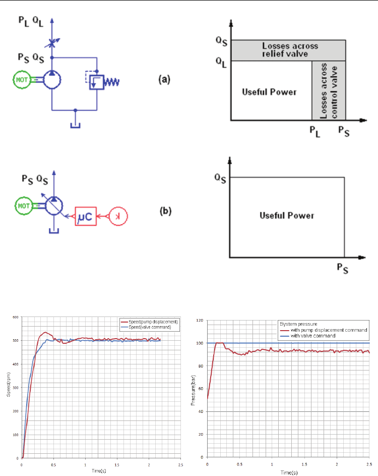
Two variants of adjusting the flow within the primary sector of a hydrostatic transmission
were tested in comparison, according to fig.23.
-
variant (a), where capacity of the pump within the primary sector is set, while flow
adjustment is performed by means of an adjustable throttle (Popescu et al., 2009). In this
case, the extra flow is discharged at the tank through a normally closed pressure valve;
-
variant (b), where in the primary sector a hydraulic servopump with adjustable
capacity is used.
In both variants, tests were performed for a constant load of 20 Nm at the shaft of hydraulic
motor within the secondary sector of transmission.
After calibrating the adjustment model of mixed adjustment transmission, process carried
out by means of the numerical simulation network, the motor within the secondary sector
was set on maximum capacity and the two flow adjustments systems for the pump in the
primary sector were analyzed comparatively (b. Drumea et al., 2010). Tests were performed
for a 20 Nm load at the shaft of the motor within secondary sector of transmission.
Experimentally, systems were excited cyclically, with or without energy efficiency, with
step-type control signals of rotational speed (500 rpm), fig.24, and ramp-type signals, fig.25.
We recorded evolution over time of rotational speed of the hydraulic motor shaft, fig.24 (a),
fig.25 (a) and pressures within primary hydraulic circuit, fig.24 (b), fig.25 (b).
The two systems for adjusting the flow within the primary sector of transmission have been
excited with a control signal of the speed of hydraulic motor within the secondary sector,
corresponding to a specific preset profile.
Numerical Simulations - Applications, Examples and Theory
440
Fig. 23. Variants of adjusting the flow within the primary sector of a hydrostatic
transmission
a) b)
Fig. 24. a) Variation of rotational speed of hydraulic motor within secondary sector to a step
type excitation signal of flow adjustment systems within the primary sector, b) Variation of
pressure along the primary circuit to a step type excitation signal of flow adjustment
systems within the primary sector
