Amano R.S., Sunden B. (Eds.) Computational Fluid Dynamics and Heat Transfer: Emerging Topics
Подождите немного. Документ загружается.

Sunden CH001.tex 17/8/2010 20: 14 Page 6
6 Computational Fluid Dynamics and Heat Transfer
1.2 Numerical Formulation
1.2.1 Governing equations
The conservation equations governing incompressible steady flow problems are
expressed in the following general form:
div[ρ
V −
grad()] = S
(1)
where is any transport variable,
V the velocity vector, ρ the density of the fluid,
the diffusive coefficient, and S
is the source term of variable .
With ξ,η, and ζ representing the general curvilinear coordinates in three-
dimensional framework, the transport equation (1) can be expressed as:
1
J
∂ρU
∂ξ
+
∂ρV
∂η
+
∂ρW
∂ζ
=
1
J
∂
∂ξ
J
(q
11
ξ
)
+
1
J
∂
∂η
J
(q
22
η
)
+
1
J
∂
∂ζ
J
(q
33
ζ
)
+ S
CD
+ S
(ξ,η,ζ)
(2)
where U, V, and W are contravariant velocities defined as follows:
U = j
11
u +j
21
v +j
31
w (3a)
V = j
12
u +j
22
v +j
32
w (3b)
W = j
13
u +j
23
v +j
33
w (3c)
J istheJacobiancoefficient,q
ij
and j
ij
(i =1−3and j =1−3)arethetransforma-
tion coefficients (refer to the appendix), and S
CD
is the cross-diffusion term (refer
to the appendix).
1.2.2 Discretization
The computational domain is uniformly divided into hexahedral control volumes,
and the discretization of transport equation (2) is performed in the computational
domain following the finite-volume method.
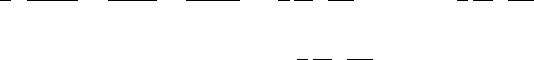
Integrating equation (2) over a control volume as shown in Figure 1.1 and
applyingthe Gauss DivergenceTheorem in conjunction withcentraldifference for
diffusion, we have:
F
e
− F
w
+ F
n
− F
s
+ F
t
− F
b
= S
V + S
CD
V (4)
where F
f
represents the total fluxes of across the cell face f (f=e, w, b, s, b, t).
Sunden CH001.tex 17/8/2010 20: 14 Page 7
A higher-order bounded discretization scheme 7
W
z T
w
t
s
S
b
b
P
e
x E
n
Figure 1.1. A typical control volume.
Taking the east face as an example, the total fluxes across it can be written as:
F
e
= (ρU)
e
−
J
J
11
e
(
E
−
P
) (5)
In the above equation, the cell face values of can beapproximated with different
schemes.
For the first-order upwind scheme, the cell face value is expressed as:
e
=
P
if U
e
> 0
e
=
E
if U
e
< 0
(6)
Substituting equations (5) and (6) into equation (4), we have:
A
P
P
=
i=E,W,N,S,T,B
A
i
i
+ S
C
(7)
wheresubscriptidenotesneighboringgridpoints,A
P
andA
i
thecoefficientsrelating
to the convection and diffusion, and S
c
is the source term.
1.2.3 Higher-order schemes
Theapproximationofconvectionhasadecisiveinfluenceontheoverallaccuracyof
the numerical simulations for a fluid flow.The first-order schemes such as upwind,
hybrid, and power-law all introduce the second-order derivatives that then lead
to falsely diffusive simulated results. Therefore, the higher-order schemes have
Sunden CH001.tex 17/8/2010 20: 14 Page 8
8 Computational Fluid Dynamics and Heat Transfer
to be used to increase the accuracy of the solution. Generally, with uniform grid
spacing, the higher-order inter polation schemes can be written in the following
weighted-average form:
e
=
P
+
1
4
[(1 −κ)
−
e
+ (1 +κ)
e
]ifU
e
> 0
e
=
E
−
1
4
[(1 −κ)
+
e
+ (1 +κ)
e
]ifU
e
< 0 (8)
where
−
e
=
P
−
W
,
e
=
E
−
P
,
+
e
=
EE
−
E
and κ is the weighted-
average coefficient. In equation (8), the underlined terms represent the fragments
of the first-order upwind scheme. Therefore, the higher-order schemes can be
implemented in a deferred correction approach proposed by Khosla and Rubin
[9]; that is,
n+1
f
=
UP,n+1
f
+ (
HO,n
f
−
UP,n
f
) (9)
where n indicates the iteration level, and UP and HO refer to the upwind and
higher-orderschemes,respectively.Theconvectivefluxescalculatedbytheupwind
schemes are combined with the diffusion term to form the main coefficients of the
difference equation, while those resulting from the deferred correction terms are
collected into the source term, say, S
DC
. Such a treatment leads to a diagonally
dominant coefficient matrix and enables a higher-order accuracy to be achieved at
a converged stage.
With this method, the deferred correction source term, taking east–west
direction as an example, is calculated by:
S
DC
=
1
4
U
+
e
U
e
[(1 +κ)
e
+ (1 −κ)
−
e
] −U
−
e
U
e
[(1 +κ)
e
+ (1 −κ)
+
e
]
− U
+
w
U
w
[(1 +κ)
w
+ (1 −κ)
−
w
] +U
−
w
U
w
[(1 +κ)
w
+ (1 −κ)
+
w
]
(10)
where U
±
e
is defined as:
U
±
f
=
1 ±sgn(U
f
)
2
If κ is fixed at a suitable constant value everywhere, several well-known schemes
can be formed.
However,theschemeslistedinTable1allsufferfromboundednessproblem;that
is, the solutions may display unphysical oscillations in regions of steep gradients,
which can be sufficiently serious to lead to numerical instability.
1.2.4 Weighted-average coefficient ensuring boundedness
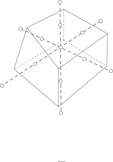
Based on the variable normalization proposed by Leonard [4], with a three-node
stencil as shown in Figure 1.2, we introduce a normalized variable defined as:
˜
=
−
U
D
−
U
(11)
Sunden CH001.tex 17/8/2010 20: 14 Page 9
A higher-order bounded discretization scheme 9
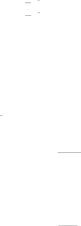
Table 1.2. Typical interpolation schemes
Expression for
e
when u> 0 Leading truncation error term
1/2(3
P
−
W
) 3/8x
3
1/2(
E
+
P
) 1/8x
2
1/8(3
E
+6
P
−
W
) 1/16x
3
1/6(2
E
+5
P
−
W
) −1/24x
2
F
U
WEPwe
F
C
F
f
F
D
Figure 1.2. Three-node stencil.
where the subscripts U and D represent the upstream and downstream loca-
tions, respectively. In the normalized form, the higher-order schemes can be
rewritten as:
˜
f
=
˜
C
+
1
4
[(1 +κ)(1 −
˜
C
) +(1− κ)
˜
C
] (12)
See Figure 1.2 for notations of the terms. Solving for κ,
κ =
4
˜
f
− 4
˜
C
− 1
1 −2
˜
C
(13)
In order to ensure boundedness, theTVD constraints can be used; that is,
˜
f
≤ 1,
˜
f
≤ 2
C
,
˜
f
≥
˜
C
for 0 <
˜
C
< 1
˜
f
=
˜
C
for
˜
C
≤ 0or
˜
C
≥ 1 (14)
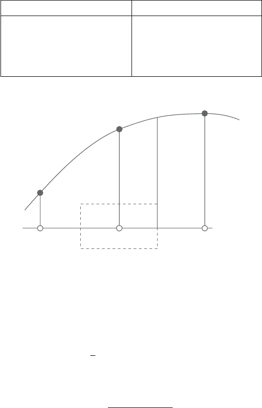
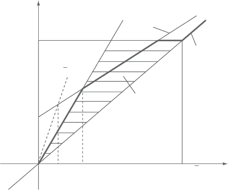
which correspond to the triangle region shown in Figure 1.3.
Sunden CH001.tex 17/8/2010 20: 14 Page 10
10 Computational Fluid Dynamics and Heat Transfer
TVD
constraints
A
1.0
B 1.0
CF
c
WACEB
QUICK
~
2F
c
~
F
f
~
F
c
~
Figure 1.3. Diagrammatic representation of the TVD constraint and WACEB
scheme.
The Taylor series expansion shows that the first two leading trunca-
tion error terms of the interpolation scheme (7) are 1/4(κ −1/2)x
2
and
1/8(1−κ)x
3
. Therefore, the scheme has at least the second-order accuracy.
The maximum accuracy (third order) can be achieved if κ is set equal to 1/2.Thus,
thescheme canbe formed insuch awaythat κ lies asclose aspossibleto 1/2, while
satisfying theTVD constraints. Based on this idea, the normalized cell face value
can be computed by the following expressions:
˜
f
=
⎧
⎪
⎪
⎪
⎪
⎨
⎪
⎪
⎪
⎪
⎩
˜
C
˜
C
/∈ [0,1]
2
˜
C
˜
C
∈ [0,0.3)
3/8(2
˜
C
+ 1)
˜
C
∈ [0.3,5/6]
1
˜
C
∈ (5/6,1]
(15)
As shown in Figure 1.3, TVD constraints are overly restrictive according to
convection boundedness criterion (CBC). However, the use of a larger multiplying
constant will not noticeably increase the accuracy. The reasons are that, first, the
constant affects the accuracy only in the range from A to B (see Figure 1.3), and
this range varies at most from 0 to 0.3 (if we use constant 3, A=0.1666 and
B=0.3). Secondly, even with the smaller constant, the accuracy of the scheme is
still second order. Therefore, the present WACEB (weighted-average coefficient
ensuring boundedness) scheme employs normalized variable formulation (15) to
calculate the weighted-average coefficient to preserve boundedness.
Sunden CH001.tex 17/8/2010 20: 14 Page 11
A higher-order bounded discretization scheme 11
1.00
0.50
0.00
κ
−0.5
−1.0
−2.5 −0.0 2.50
Φ
c
∼
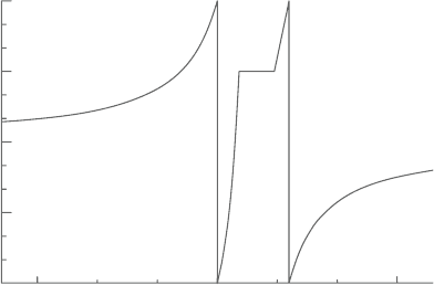
Figure 1.4. Thevariationinweighted-averagecoefficientwithnormalizedvariable.
From equations (7) and (8), the weighted-average coefficient can be given by:
κ =
⎧
⎪
⎪
⎪
⎨
⎪
⎪
⎪
⎩
1/(1 −2
˜
C
)
˜
C
/∈ [0,1]
(4
˜
C
− 1)/1 −2
˜
C
˜
C
∈ [0,0.3)
(3 −4
˜
C
)/(1 −2
˜
C
)
˜
C
∈ [0.3,5/6]
1/2
˜
C
∈ (5/6,1]
(16)
The variation in κ with
˜
C
is shown in Figure 1.4. It is easy to see that the present
WACEB scheme satisfies convectivestability condition [2]. It is necessary to men-
tion that the above algorithm is formulated on the assumption of the constant grid
spacing. For nonuniform grids, the weighted-average coefficient will also be the
function of the grid spacing aspect ratio.
1.3 Test Problem and Results
The governing transport equations are solved by using the nonstaggered finite-
volume method. A special interpolation procedure developed by Rhie and Chow
[10] is usedto preventpressure oscillations due to nonstaggeredgrid arrangement.
Pressure and velocity coupling is achieved through the SIMPLE algorithm [8].
Itisnecessaryto mentionthatQUICKandWACEBschemesallneed toemploy
two upstream nodes for each cell face, which mandates one to involve a value
outside the solution domain for a near-boundary control volume. Therefore, the
upwind scheme is used for all the control volume adjacent to boundaries.
1.3.1 Pure convection of a box-shaped step profile
TheflowconfigurationshowninFigure1.5constitutesatestproblemforexamining
theperformanceofnumericalapproximationtoconvectionbecauseoftheextremely
Sunden CH001.tex 17/8/2010 20: 14 Page 12
12 Computational Fluid Dynamics and Heat Transfer
1.0
0.15
0.15
Φ = 0
v
u
1.0
0.15
0.15
Φ = 1
Φ = 0
V
Figure 1.5. Pure convection of a box-shaped step by a uniform velocity field.
sharp gradient in a scalar. This is a linear problem in which the velocity field is
prescribed. The calculations are performed with two different uniform meshes,
29×29 and 59×59.
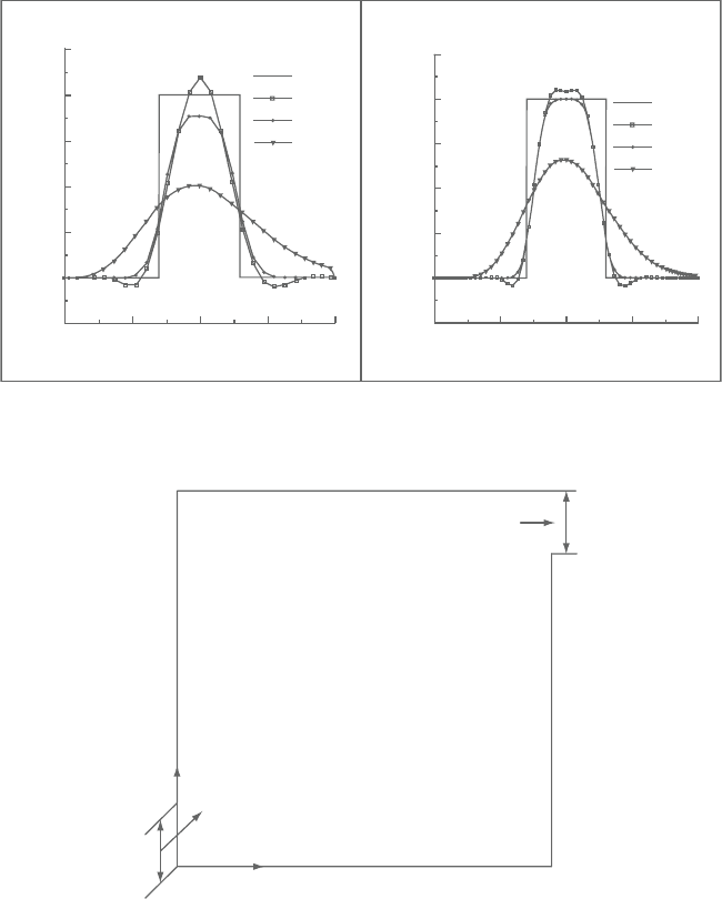
Comparisons of the numerical solutions obtained with the upwind, QUICK,
and WACEB schemes are presented in Figure 1.6(a) and (b). It can be seen that
the upwind scheme results in a quite falsely diffusive profile for the scalar even
with the finer mesh. Although the QUICK scheme reduces such a false diffusion,
it produces significant overshoots and undershoots. Unlikely, the WACEB predicts
a fairly good steep gradient without introducing any overshoots or undershoots.
Therefore,weconcludethattheWACEBschemeresolvestheboundednessproblem
while reserving a higher-order accuracy.
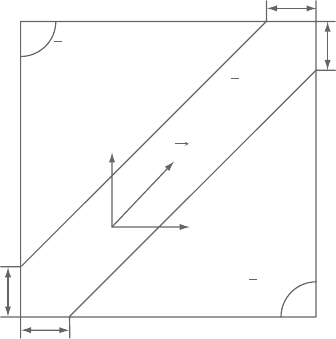
1.3.2 Sudden expansion of an oblique velocity field in a cavity
Thegeometry underconsideration isdepictedinFigure1.7.Theflow isassumed to
be steady and laminar.At the inlet, U-velocity and V-velocity are given a constant
valueof U
ref
.Theboundary conditionsat the outletare ∂U/∂x =0 and∂V/∂x =0.
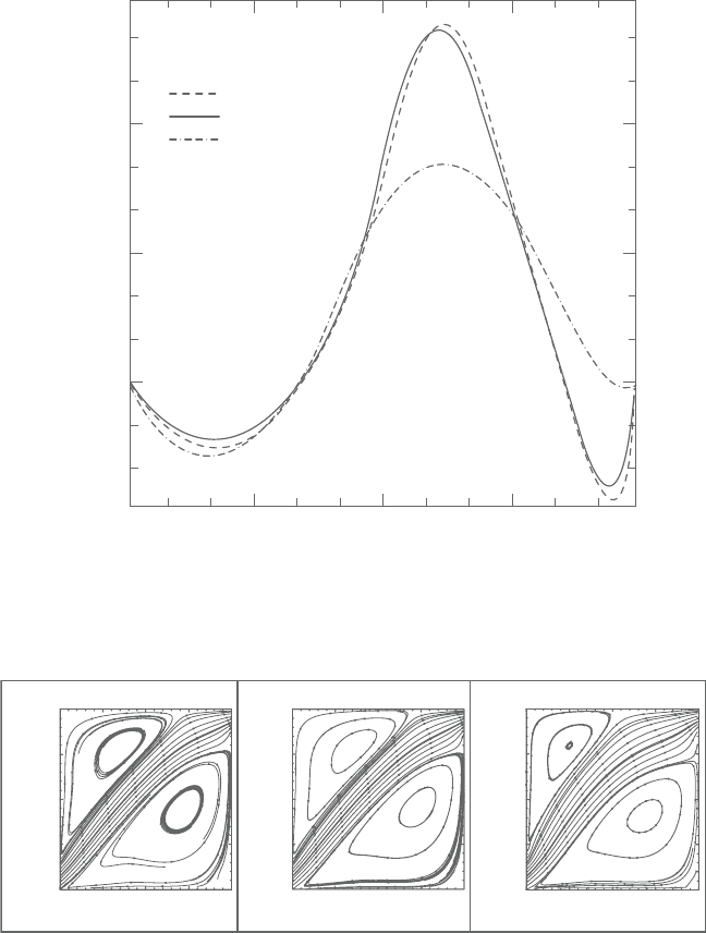
Thecalculations areperformed onthe uniformmeshes(59×59). Figure1.8 shows
the comparison of U-velocity along the vertical central lines of the cavity for the
Reynolds number 400. It is noticed that the upwind scheme cannot predict the
secondary recirculation region well, which should appear near the upper side of
the cavity and smears out the steep gradients of the velocity profile near the main-
stream.WeobservethatboththeWACEBandQUICKschemesdistinctivelypredict
this secondary recirculating region. Furthermore, it is noteworthy to observe that
both produce very similar results.The streamline patterns predicted with the three
schemes are all shown in Figure 1.9. It is clearly seen, again, that the upwind
Sunden CH001.tex 17/8/2010 20: 14 Page 13
A higher-order bounded discretization scheme 13
1.250
1.000
0.750
0.500
0.250
0.000
0.000 0.250 0.500 0.750 1.000
−0.250
Φ
Y
29 × 29
1.250
(b)(a)
1.000
0.750
0.500
0.250
0.000
0.000 0.250 0.500 0.750 1.000
−0.250
Φ
Y59 × 59
Exact
Quick
Waced
Upwind
Exact
Quick
Waced
Upwind
Figure 1.6. Scalar profiles along the center line.
L
y
L
x
0.15L
0.15L
Figure 1.7. Geometry of a cavity.
scheme predicts a much smaller vortex on the upper left side of the cavity and
much wider mainstream region than the QUICK and WACEB schemes.The com-
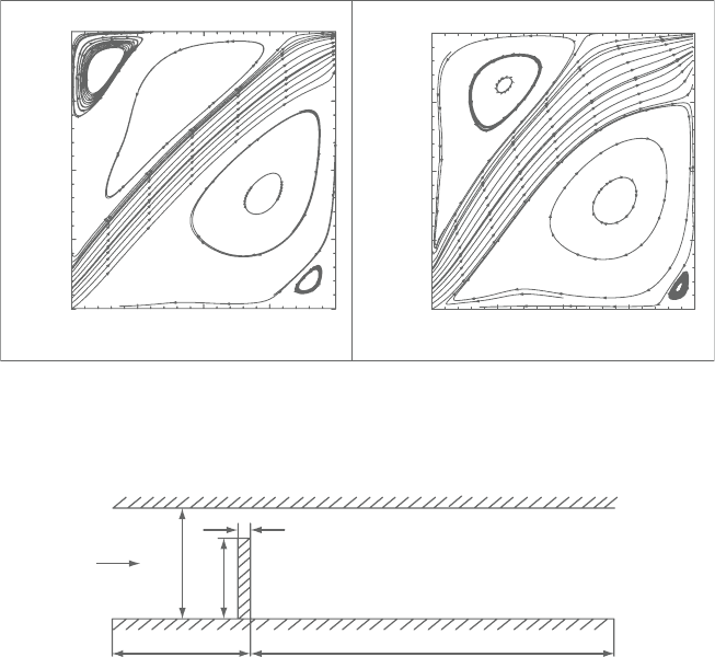
putations were further extended to a higher Reynolds number up to 1,000. At this
Reynolds number, the QUICK scheme produces a “wiggle solution.” Figure 1.10
shows streamline patterns predicted with theWACEB and upwind schemes.These
two schemes give very different flow patterns; with the increase in the Reynolds
number, the convectionis enhanced and diffusion is suppressedand then the “dead
water regions” should have less effect on the mainstream region. The results with
Sunden CH001.tex 17/8/2010 20: 14 Page 14
14 Computational Fluid Dynamics and Heat Transfer
0.250
0.500
QUICK
WACEB
UPwind
0.750
U/U
ref
0.000
0.000 0.250 0.500
y/L
0.750 1.000
−0.25
Figure 1.8. U-velocity profile along the vertical center line of the domain
(Re=400).
1.00
0.75
0.50
0.25
0.00
0.00 0.25 0.50
x/L
0.75 1.00
y/L
(a) (b)
1.00
0.75
0.50
0.25
0.00
0.00 0.25 0.50
x/L
0.75 1.00
y/L
(c)
1.00
0.75
0.50
0.25
0.00
0.00 0.25 0.50
x/L
0.75 1.00
y/L
Figure 1.9. Streamlines for sudden expansion of an oblique velocity field
(Re=400): (a) QUICK; (b) WACEB; (c) upwind.
the WACEB scheme clearly show this trend. It is also noted that the WACEB
scheme produces two additional vortices at the two corners of the cavity. However,
the upwind scheme predicts only a very small additional vortex at the lower right
corner and fails to capture the additional vortex at the upper left corner.
Sunden CH001.tex 17/8/2010 20: 14 Page 15
A higher-order bounded discretization scheme 15
1.00
0.75
0.50
0.25
0.00
0.00 0.25 0.50
x/L
0.75 1.00
1.00
0.75
0.50
0.25
0.00
0.00 0.25 0.50
x/L
0.75 1.00
y/L
y/L
(a)
(b)
Figure 1.10. Streamlines for sudden expansion of an oblique velocity field
(Re=1,000): (a)WACEB; (b) upwind.
0.1H
6H
30H
H
S = 0.75H
Figure 1.11. Geometry of flow over a fence.
From the above discussions, it is concluded that the solution with the WACEB
scheme is comparable to that with the QUICK scheme. Even under highly con-
vective conditions in which the unbounded QUICK scheme may produce “wiggle
solutions,” the bounded WACEB scheme still produces a reasonable solution.
1.3.3 Two-dimensional laminar flow over a fence
A two-dimensional laminar flow over a fence (see Figure 1.11) with the Reynolds
number based on the height of the fence, the mean axial velocity of 82.5, and the
blockage ratio (s/H) of 0.75 is a benchmark case study. The boundary conditions
at the inlet are prescribed as a parabolic profile for the axial velocity U and zero
for the cross-flow velocity V. At the outlet, the boundary conditions are given as
∂U/∂x =0 and ∂V/∂x =0. The present study shows that the grid-independence
results can be achieved with 150×78 uniform meshes for all the schemes.