Ahsan A. Two Phase Flow, Phase Change and Numerical Modeling
Подождите немного. Документ загружается.


Modeling and Simulation of the Heat Transfer Behaviour
of a Shell-and-Tube Condenser for a Moderately High-Temperature Heat Pump
69
where hN is the average heat transfer coefficient for a vertical column of N tubes, and h
1
is
the heat transfer coefficient of the top tube in the row.
3.8 Tube-side heat transfer coefficient
According to flow regime, the tube-side heat transfer coefficient h
t
can be computed by
following relations (Patel & Rao, 2010):
1.33
0.3
0.0677(Re Pr )
[3.657 ]
10.1Pr(Re )
i
tt
ti
t
i
t
tt
d
hd
L
Nu
d
k
L
== +
+
for Re
t
<2300 (16)
-
-
0.67
0.67
(Re 1000)Pr
8
{[1()]}
1 12.7 (Pr 1)
8
t
tt
ti i
t
t
t
t
f
hd d
Nu
kL
f
== +
+
for 2300<Re
t
<10000 (17)
0.8 1/3 0.14
0.027Re Pr ( )
to t
ttt
twt
hd
Nu
k
μ
μ
== for Re
t
>10000 (18)
and
Re
tti
t
t
vd
ρ
μ
= (19)
2
4
p
t
t
o
t
t
n
m
v
d
N
π
ρ
=
(20)
Pr
t
p
t
t
t
c
k
μ
= (21)
-
-
2
t10
f(1.82logRe1.64)
t
=
(22)
where
Nu
t
is tube-side Nusselt number, Re
t
is tube-side Reynolds number, Pr
t
is tube-side
Prandtl number,
k
t
is the thermal conductivity [W/mK], d
i
is the tube inside diameter[m], L
is tube length[m],
v
t
is tube-side fluid velocity [m/s],
t
m
is tube-side mass flow rate[kg/s], d
o
is tube outside length [m],
ρ
t
is tube-side density [kg/m
3
], n
p
is number of tube passes, N
t
is
number of tubes,
μ
t
is viscosity at tube wall temperature [Pa-s], μ
wt
is viscosity at core flow
temperature [Pa-s],
f
t
is Darcy friction factor (Hewitt, 1998).
3.9 Coefficient of variation of root-mean-square error
This study uses the coefficient of variation of root-mean-square error (CV) to indicate how
well the model predicting value fits the experimental data, defined as follows:
Two Phase Flow, Phase Change and Numerical Modeling
70
-
2
1
1
()
100%
n
ii
i
n
i
i
yx
n
CV
y
n
=
=
=×
(23)
where
x
i
is the predicting value by present model, y
i
is experimental data, and n is the
number of experimental data set.
3.10 Solution procedures
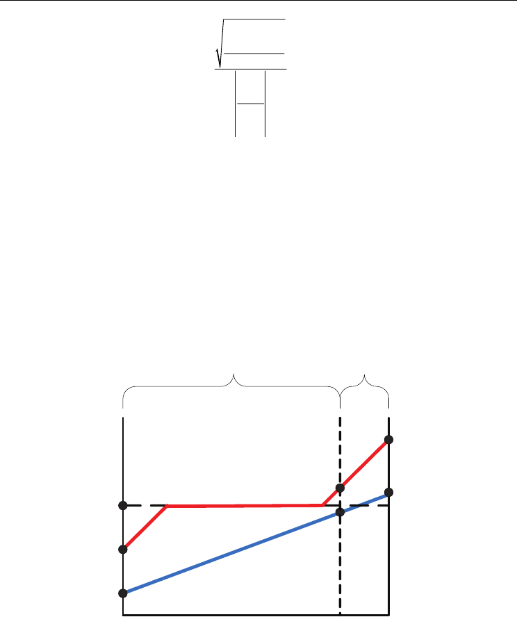
According to the configuration of the horizontal baffles in the heat exchanger, the condenser
can be separate into two regions, Section-I and II, as indicated in Figure 2-4. Section-I has
three tube passes and two horizontal baffles, while Section-II has nine tube passes without
any horizontal baffle. In Section-I, both water and refrigerant are in single phase. The
temperature variations of the refrigerant and water streams are shown in Figure 4. In the
interface between Section-I and II, the entering water temperature
T
w
and the leaving
refrigerant temperature Tr should be determined by iteration method.
T
ri
T
ro
T
wi
T
wo
T
w
T
c
0
L
T
r
II I
Fig. 4. Temperature variations of two steams in the condenser
The total heat transfer rate of the condenser is the sum of individual heat transfer rate of the
two sections.
,,
M
odel Model I Model II
QQ Q=+
(24)

Modeling and Simulation of the Heat Transfer Behaviour
of a Shell-and-Tube Condenser for a Moderately High-Temperature Heat Pump
71
where
,
Q
M
odel I
and
Model,II
Q
represent the heat transfer rate in Section-I and II, respectively,
and can be determined as following equations.
,
()
M
odel I Model m I
QUAFT=Δ
(25)
,
()
M
odel II Model m II
QUAFT=Δ
(26)
The overall heat transfer coefficient for the two sections can be calculated by
,I
1
ln( )
11
()
2
Model
o
o
io
fo fi
s,I m i t
U
d
d
dd
RR
hk dh
=
++++
(27)
,II
1
ln( )
11
()
2
Model
o
o
io
fo fi
s,II m i t
U
d
d
dd
RR
hk dh
=
++++
(28)
The heat transfer areas for the two sections can be calculated as
,IotI
ALdN
π
= (29)
,II o t II
ALdN
π
= (30)
The tube-side heat transfer rates for Section-I and II are:
,,wwIwII
QQ Q=+
(31)
-
,,
()( )
wI rI r ri r Ex
p
mI
QQmhhUAT== = Δ
(32)
-
w,I
wwo
w
p
w
Q
TT
mc
=
(33)
-
,
()( )
wII w
p
ww wi Ex
p
mII
QmcTTUAT==Δ
(34)
where the log mean temperature difference for Section-I and II can be determined by:
---
-
-
,
()()
ln( )
ri wo r w
mI
ri wo
rw
TT TT
T
TT
TT
Δ=
(35)
---
-
-
,
()( )
ln( )
rw rowi
mII
rw
ro wi
TT T T
T
TT
TT
Δ=
(36)

Two Phase Flow, Phase Change and Numerical Modeling
72
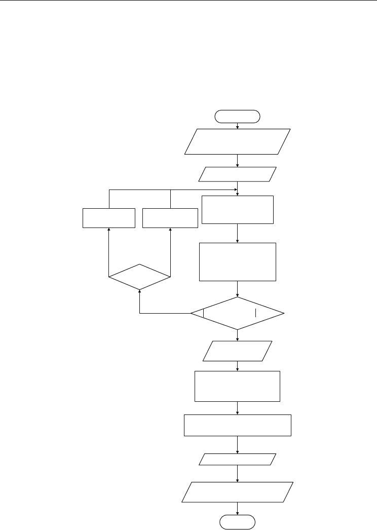
The present modeling procedures for determining the total heat transfer rate are shown as
Fig. 5 and detailed as following steps:
1. Input design parameters and geometry factors:
Design parameters include the refrigerant inlet and outlet temperatures (
T
ri
,
T
ro
), the
refrigerant inlet pressure
P
ri
, the water inlet and outlet temperatures (T
wi
, T
wo
), the water
and refrigerant mass flow rate (
wr
m, m
), the condensing temperature T
c
, and the number
of tubes
N
t
. Geometry factors include the tube inside and outside diameters (d
i
, d
o
), the
shell inside diameter
D
i
, the baffles distance B, the tube pitch P
T
,
and the tube length L.
2. Initial guess a shell-side outlet temperature (
T
r
) for Section-I.
3. Determine relative physical quantities for Section-I:
The physical quantities include the heat transfer areas, the shell-side hydraulic
diameter,
the tube-side fluid velocity, the Reynolds numbers, the tube- and shell-side
heat transfer coefficients, overall heat transfer coefficient, log mean temperature
difference, the heat transfer rate (
w,I
Q
) computed from water-side data and the heat
transfer rate (
Model,I
Q
) predicting by present model.
4. If the percent error
-
w,I Model,I
w,I
QQ
Q
<0.01%, then output
T
r
, T
w
,
Model,I
Q
and
w,I
Q
and go to
step 5. If not, gives a new shell-side outlet temperature and goes back to step 2. Iteration
of the previous steps until the relative error is within the value of 0.01%.
5. Determine relative physical quantities for Section-II:
The relative physical quantities needing to determine in the section include the heat
transfer area (
A
II
), the shell-side heat transfer coefficient (h
s,II
), the overall heat transfer
coefficient (
U
Model,II
), the log mean temperature difference (ΔT
m,II
), the heat transfer rate
(
w,II
Q
) computing from water-side data, and the heat transfer rate (
Model,II
Q
) predicting
by present model.
6. Compute total heat transfer rate by water-side data (
w
Q
) and present model (
Model
Q
)
7. Output calculation results.
4. Results and discussions
A shell-and-tube condenser designed for moderately high-temperature heat pump system
were built and tested in this study. Twenty-seven sets of experiment results are shown in
Table 1.
By observing the data listed in Table 1, we found that, except for the data set 2-5, the water
outlet temperature is higher than the condensing temperature for most data sets. These
results were in line with our expectations. This is because that at the beginning of design
stage, in order to effectively recover the sensible heat from superheating vapour at
refrigerant-side inlet of the condenser, two horizontal baffles were placed on the refrigerant-
side to extend the contact time between the refrigerant and the water.
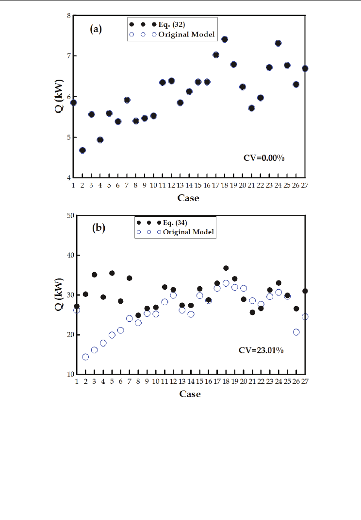
The new shell-and-tube condenser has divided into two sections, according to whether or not
the refrigerant-side has placed horizontal baffles, as shown in Figure 2. By using the theoretical
model and solution procedure introduced previously, numerical simulation of heat transfer
behaviour was carried out for Section-I first and then for Section-II. After substituting the same
conditions similar to the 27 sets of experiments, the preliminary comparison of the simulated
and the experimental results are shown in Figure 6a and Figure 6b.
Modeling and Simulation of the Heat Transfer Behaviour
of a Shell-and-Tube Condenser for a Moderately High-Temperature Heat Pump
73
Examining Figure 6a showed that the simulation results for the Section-I of condenser are very
close to the deduced results from the experiment. This is because in the Section-I iteration
process solving the heat transfer rates for refrigerant- and the water-side, the convergence
constrain was set within 0.01% in order to meet energy conservation requirements.
The output results from Section-I calculation were set as the input data for the following
Section-II calculation. The computation results for the Section-II calculation were compared
to the deduced results from Eq. (34), and the difference between the two results is shown in
Figure 6b, the CV value of Section-II is 23.01%.
No
Yes
YesNo
)
r
h-
ri
(h
r
m=
Ir,
Q eminDeter
r,I
Q =
w,I
Q
)
pw
c
w
m/(
Iw,
Q-
wo
T =
w
T
(35) Eq. by TΔ
Im,
Im,
TΔ
I
A
IModel,
U=
IModel,
Q
Start
conditions Design:Input
factors geometry
properties ynamicmodther
2/)T+T(=T:Guess
crir
I Section
De As, ,
I
A etermineD
v ,
IModel,
U ,
t
h ,
Is,
h Re,
0.01%<
w,I
Q)/
Model,I
Q-
w,I
Q(
I,Model
Q>
I,w
Q
2/)
r
T+
c
T(=
new
r
T
2/)
r
T+
ri
T(=
new
r
T
Iw,
Q ,
w
T ,
r
T:Output
II Section
IIModel,
U ,
IIs,
h ,
II
A eminDeter
(36) Eq. by TΔ
IIm,
)
wi
T-
w
(T
pw
c
w
m=
IIw,
Q etermineD
II,m
TΔ
II
A
II,Model
U=
IIModel,
Q
IIModel,
Q ,
IIw,
Q :Output
IIw,
Q+
Iw,
Q=
w
Q :Output
IIModel,
Q+
IModel,
Q=
Model
Q
End
I,Model
Q
Fig. 5. Algorithm of the model

Two Phase Flow, Phase Change and Numerical Modeling
74
Case
T
wi
(°C)
T
wo
(°C)
w
m
(kg/s)
T
ri
(°C)
P
ri
(MPa)
T
ro
(°C)
T
c
(°C)
r
m
(kg/s)
H
Q
(kW)
1 24.9 74.9 0.16 100.4 2.20 64.3 71.8 0.19 33.4
2 25.0 45.1 0.41 70.5 1.20 39.1 46.2 0.18 35.0
3 25.1 45.4 0.48 71.9 1.22 39.7 47.0 0.21 40.8
4 24.9 55.1 0.27 80.2 1.50 46.6 55.2 0.18 34.6
5 25.1 55.1 0.33 79.4 1.53 47.6 55.9 0.22 41.3
6 25.0 64.9 0.20 91.0 1.84 53.6 63.7 0.18 34.1
7 25.1 65.1 0.24 89.0 1.88 57.0 64.7 0.23 40.4
8 24.9 70.7 0.16 97.1 2.09 59.1 69.4 0.17 30.5
9 25.0 73.7 0.16 97.3 2.23 64.4 72.2 0.19 32.4
10 25.0 74.0 0.16 98.0 2.22 63.7 72.1 0.19 32.7
11 25.1 75.0 0.18 99.3 2.26 67.1 72.9 0.23 38.8
12 25.1 75.1 0.18 99.2 2.24 71.1 72.5 0.24 38.1
13 24.9 75.2 0.16 100.5 2.22 64.5 72.1 0.19 33.6
14 24.9 75.4 0.16 102.9 2.23 61.0 72.2 0.19 33.9
15 25.1 75.4 0.18 99.3 2.25 71.0 72.8 0.24 38.3
16 25.2 78.3 0.16 104.0 2.34 68.4 74.5 0.21 35.5
17 25.1 78.8 0.18 103.7 2.43 73.1 76.2 0.25 40.4
18 25.0 80.0 0.19 104.1 2.47 73.8 76.9 0.28 44.7
19 25.1 80.6 0.18 103.4 2.49 74.8 77.3 0.27 41.4
20 25.1 84.8 0.14 106.9 2.65 78.0 80.2 0.24 35.6
21 24.9 85.0 0.12 108.2 2.63 73.9 79.8 0.20 31.8
22 34.9 84.3 0.16 107.4 2.62 77.8 79.8 0.22 32.9
23 35.0 85.5 0.18 108.5 2.71 78.7 81.4 0.25 38.3
24 35.1 85.1 0.19 109.5 2.70 78.5 81.0 0.27 40.7
25 35.1 85.1 0.17 109.0 2.69 79.0 81.0 0.25 37.0
26 39.9 75.2 0.22 104.3 2.26 63.5 72.9 0.19 33.1
27 40.1 75.3 0.25 100.9 2.31 69.3 73.9 0.23 38.0
Table 1. Experimental results
Modeling and Simulation of the Heat Transfer Behaviour
of a Shell-and-Tube Condenser for a Moderately High-Temperature Heat Pump
75
Fig. 6. The computation results of heat transfer rate for (a) Section-I and (b) Section-II
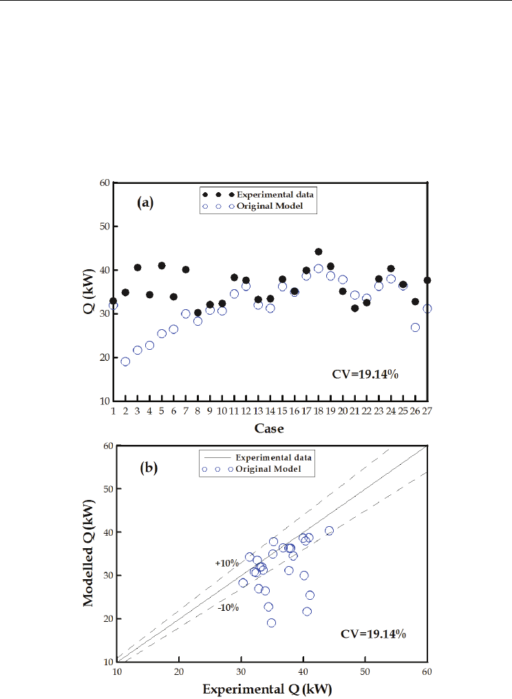
From Figure 7a and Figure 7b, the difference from data sets numbered 2-7 and 26-27 are
greater than 10%, the percent error for the rest data sets are all within 10%. Table 1 also
showed that, as compared with the other data sets, these eight cases with larger difference
occurred when changing water outlet temperature and mass flow rate. We know from the
theoretical model that the major variables of heat transfer rate of condenser include water
inlet/outlet temperatures, water mass flow rate, and overall heat transfer coefficient U.
Among them, the overall heat transfer coefficient is influenced by the tube-side as well as
the shell-side heat transfer coefficients. The change in tube-side heat transfer coefficient is
mainly due to the effect of water flow rate, while the shell-side heat transfer coefficient is
Two Phase Flow, Phase Change and Numerical Modeling
76
influenced by the flow characteristic of refrigerant and tube arrangement in the condenser,
which make the actual heat transfer behaviour much complex and difficult to accurately
predict. Thus, observation of the effect of operating parameters on the overall heat transfer
coefficient, establishment of a rule governing the overall heat transfer coefficient of the
changing parameters, and the establishment of a modified correlation of heat transfer
coefficient can all help increase the prediction accuracy of the model for heat transfer rate.
Since in this study the hot water inlet temperature was almost constant, thus the operating
parameters to be discussed include water outlet temperature (T
wo
), and water mass flow-rate
(
w
m
).
Fig. 7. (a) Comparison between the simulation results and the experimental data, (b) relative
error analysis for overall heat transfer rate

Modeling and Simulation of the Heat Transfer Behaviour
of a Shell-and-Tube Condenser for a Moderately High-Temperature Heat Pump
77
As the water outlet temperature changes due to various physical parameters such as water
mass flow rate, the ratio of the model predicted to experimental data for the overall heat
transfer coefficient at Section-II, U
model,II
/U
exp,II
, is depicted in Figure 8.
Fig. 8. Variation of the ratio of overall heat transfer coefficient with water mass flow rate
under various water outlet temperatures
Figure 8 clearly shows that when the hot water outlet temperature is higher, or when the hot
water mass flow rate is lower, the ratio of U
Model,II
/U
exp,II
becomes larger. This means that as
the hot water outlet temperature becomes higher, or when the hot water mass flow rate
becomes lower, the simulated value of the overall heat transfer coefficient will change as a
result. From this, we can learn that any change in the overall heat transfer coefficient at
Section-II has to be related to these two physical parameters. Therefore, modification of the
relationship between the overall heat transfer coefficients before and after the change in hot
water outlet temperature can be expressed as a function of hot water outlet water
temperature and mass flow rate, as Eq. (37) shows:
22
,01 2 3 4 5 ,
'( )
M
odel II wo w wo w wo w Model II
UccTcmcTmcTcmU=+ + + + +
(37)
The fitting coefficients in the equation were respectively calculated, using least square
regression method, as c
o
= 3.47931, c
1
= -0.06503, c
2
= 2.39712, c
3
= 0.018492, c
4
= 0.000340667,
and c
5
= -2.68725.
The modified overall heat transfer coefficient was used to simulate heat transfer rate for
condenser. The comparison of model predicting results versus experimental results, and the
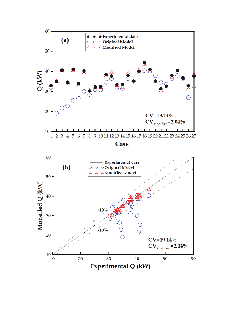
relative errors are shown in Figure 9a and 9b, respectively.
Using experimental data as a benchmark, the pre-revision calculation error derived from
the heat transfer rate prediction model was 19.14 %, but post-revision calculation error
dropped significantly to 2.03 %, indicating that the revision function in Eq. (37) is indeed
feasible. Therefore, our study will use the current revision model with modified overall
Two Phase Flow, Phase Change and Numerical Modeling
78
heat transfer coefficient for follow-up research with regard to sizing and performance
ratings.
Fig. 9. (a) Comparison between the experimental data and the simulation results by either
modified or original models, (b) relative error analysis for overall heat transfer rate
5. Cases study
5.1 Sizing problem (Estimation of unit size)
Sizing is to estimate the tube length for a heat exchanger by present model when the
inlet/outlet conditions on the refrigerant side, the inlet/outlet conditions on the hot water
side, and the diameter of the heat exchanger are known.