Ahsan A. Two Phase Flow, Phase Change and Numerical Modeling
Подождите немного. Документ загружается.

Thermal Energy Storage Tanks Using Phase Change Material (PCM) in HVAC Systems
559
where S is heat flux through the PCM capsule wall, which is calculated as follows:
()
1
11
a
p
c
S
h
θθ
λ
=−
+
(13)
The heat from the PCM to the circulating air was calculated by heat convection on the
surface of the PCM containers. The convection coefficient was calculated using the following
empirical equation for a flat surface (Incorpera et al. 1996):
13
0.8
0.037Re PrNu = (14)
The heat transfer between a container of PCM and air in the duct was enhanced by fins
extended toward the air. The fins increased the surface 18.2 times as compared to a flat surface.
The heat balance among the air entering the room, the heat transfer from outdoor air, and
the internal heat gain determined the temperature of room is as follows:
()()
r
rorir
d
cUA V
dt
θ
θθ θθ
=−+−
(15)
Charging was conducted for three hours, from 5:00 to 8:00, followed by ordinary air
conditioning from 9:00. Discharging started at 13:00 and ended at 16:00. The charging hours
were set to be equal to the discharging hours. The inlet temperature to the PCM storage tank
for the charging operation was 12°C, and the inlet temperature to the room (
θ
i
) during
ordinary air conditioning was 16°C. No temperature control was performed during the
discharging operation. During the ordinary air conditioning, the air flow rate to the room
was controlled in order to maintain the temperature of the room at 26°C. The mixture
quantities were 50, 100, 150, 200, 250, 300, 350, and 400 kg.
The room temperature was set to 25°C, as calculated by solving the heat balance for the heat
transfer through walls and windows, internal heat, and release of stored cooling from the
PCM. The calculation was conducted for two days for each condition. The results shown
herein are the results for the second day.
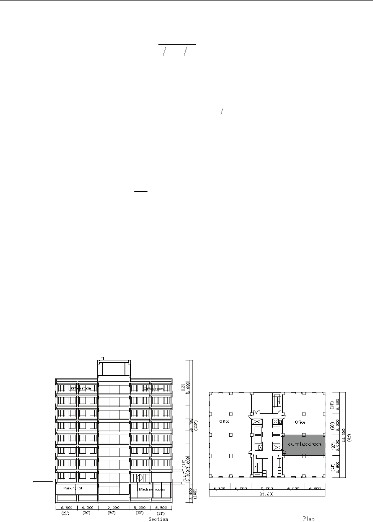
Fig. 19. Section and plan of the building used for simulation
Two Phase Flow, Phase Change and Numerical Modeling
560
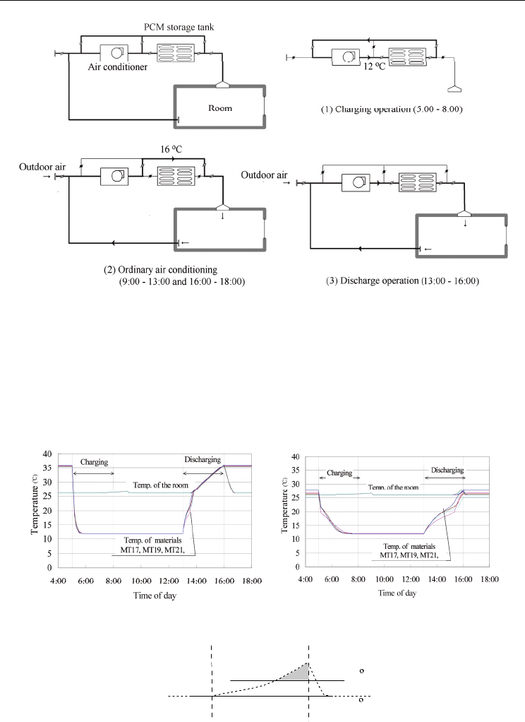
Fig. 20. Schematic diagrams of the HVAC systems used in the simulations
The results are shown in Figure 21 for 100 and 400 kg of PCM. In the left-hand figure, the
PCM mixture was cooled to air temperature (12°C) as soon as the charging operation
started. During the discharging operation, the stored heat was not large enough to maintain
the room temperature. Consequently, the room temperature was raised to 35°C. The right-
hand figure shows the results for 400 kg. The temperature during charging and discharging
operations decreased gradually due to latent heat. The stored heat had sufficient capacity to
maintain the room temperature near the set point.
Fig. 21. Comparison of temperature fluctuation using 100 kg or 400 kg of PCM
Room temp.
28
C
13:00 16:00
A
26
C
Fig. 22. Index used to evaluate the investigated effect

Thermal Energy Storage Tanks Using Phase Change Material (PCM) in HVAC Systems
561
50
100
150
200
250
300
350
400
MT17
MT19
MT21
MT23
0
2
4
6
8
10
12
14
16
18
Temp. deviation; "A"
of Fig 5
Quantity of PCM [kg]
Fig. 23. Relationship among the index, the materials, and the quantities
3.4 Discussion
The purpose of this system was to control the temperature increase while the refrigeration
machines were stopped. The evaluation of the system focused on the degree to which the
temperature fluctuated. Assuming that 28°C is the allowed indoor temperature, the area A
shown in Figure 22, which is the difference between the room temperature and 28°C, was
used as an index of temperature deviation. This index increases as the temperature in the
room increases.
Figure 23 shows the relationship between the index, the quantity of PCM, and the PCM
mixture. The temperature deviation decreased as the quantity of PCM mixture increased.
The index or the temperature deviation was very small for 400 kg of PCM, which was
equivalent to 5.4 kg/m
2
of PCM. The differences among the various materials were not
significant. The index was larger for materials with higher melting temperatures (MT23,
MT21). Because of its lower melting temperature, the most effective material was MT19.
Moreover, MT 17 melted too quickly.
In the system discussed in the present paper, the PCM would be maintained in containers
and installed in air ducts. The heat transfer between the surface of the container and the air
in the duct would be a significant problem. Since thermal conductivities of paraffin waxes
are small, the material would not be sufficiently melted or frozen, unless some
enhancements, such as fins, were adopted. Although, in the present study, fins were
adopted, for real applications, the structure of the container should be simple in order to
decrease the cost of construction.
In the present study, there was no consideration of the humidity because the program only
treated the heat transfer problem. The humidity has a large influence on thermal comfort.
The dew point of 26°C and RH 50% air is lower than 17°C, so the humidity of the room
would increase during the discharging operation. The humidity should be calculated
because the sensible heat load is relatively small in an office building.
4. Conclusions
Thermal energy storage systems are used to shift peak heat load to off-peak hours. The
performance depends on the design and installation of such systems. The performances of
two types of TES, which use ice and paraffin waxes, were analyzed. Ice storage systems

Two Phase Flow, Phase Change and Numerical Modeling
562
were analyzed as HVAC system components, and a storage system using paraffin waxes
was evaluated for use by a passive method.
Ice-on-coil and slurry ice storage system were considered. Several definitions of efficiency as
indices of evaluation were discussed. The temperature response of an ice-on-coil storage
system depends on the mixing condition. Large Archimedes numbers at the inlet result in a
longer duration of low outlet temperature. The effects of the operating conditions on the
energy and response-based efficiencies were also examined. The response-based efficiency
was more sensible to the normalized inlet enthalpy flow rate. For the slurry ice storage tank,
the time at which the outlet temperature reached 4°C varied according to experimental
conditions. Since the ice in the slurry ice tank consisted of tiny floating particles, the higher
velocity could enhance heat transfer and result in lower outlet temperatures
For storage system using paraffin waxes, an air distribution system with the PCM tank in
the air ducts was proposed. The system was used for cooling and could take advantage of
discounted electricity rates at night. The materials that could be used in the system, were
obtained by mixing paraffin waxes and fatty acids. The thermal properties of the materials
were measured. The melting temperature could be controlled by adjusting the concentration
of each material, although the latent heat of the measured mixtures was less than that of the
pure paraffin wax.
The system performance was examined through a computer simulation, and the necessary
quantity of material was evaluated. The PCM was cooled from 5:00 to 8:00 am using
discounted electricity. The stored heat was discharged from 13:00 to 16:00, when the peak
load of cooling occurred. As the refrigeration machines were stopped during this period, the
temperature of the room fluctuated. The temperature deviation was taken as an index, and
the system was evaluated. For an ordinary office building in Nagoya City, which is located
in the same climate as major cities with more than two million inhabitants in Japan, 400 kg
of PCM for 73.8 m
2
of room surface (or 5.4 kg/m
2
of PCM) could maintain the room
temperature to be constant without any cold source operation. The melting temperature
suitable for the system was approximately 19°C, which could be achieved using MT19.
5. Nomenclature
A : wall surface area
Ar
in
: Archimedes number at the inlet
c : specific heat
d
in
: diameter of the inlet of the tank
dz : thickness of PCM
g : gravitational acceleration
h: convective coefficient
H
t
: heat removed from a storage tank
H
tc
: heat removed until the outlet temperature reaches the limit temperature
IPF : (Ice Packing Factor) ratio of ice volume to tank volume (= V
ice
/V
0
)
L : heat of fusion of water
Nu : Nusselt number
Pr : Prandtl number
q : heat flow from coil
Q*: dimensionless enthalpy flow rate
Q : flow rate of inlet water

Thermal Energy Storage Tanks Using Phase Change Material (PCM) in HVAC Systems
563
Re : Reynolds number
T, t : time
Tc : limit temperature to the coils of the air handling units
u
in
: velocity of inlet water
u: velocity of water inside the tank
U : average overall heat transfer coefficient
V : airflow rate to the room
V
0
: volume of tank
V
ice
: volume of ice
x : length in the flow direction,
η
: response-based efficiency
η
0
: system efficiency
η
v
: volumetric efficiency
θ
0
: initial temperature
θ
in
: temperature of the inlet water
θ
out
: temperature of the outlet water
θ
c
: limit temperature to the coils of the air handling units
Δθ
i
: equivalent temperature difference for ice storage (= L • IPF/c)
Δθ
0
: temperature difference of the coils of the air handling units
ρ
: density of inlet water
ρ
0
: density of water at the initial temperature
ρ
ice
: density of ice
Δ ρ
: density difference between the inlet water to the tank and the initial temperature of
water in the tank
λ : thermal conductivity
θ
a
: temperature of air
θ
p
: temperature of PCM
θ
r
: temperature of the room
* indicates a dimensionless value
6. References
Barnard, N and Setterwall, F, (2003), Thermal Mass and Night Ventilation - Utilising
"hidden" Thermal Mass, Proceedings of Workshop IEA Annex 17, Indore. Mar. 2003.
Feldman, D, Shapirom, M M, Banu, D and Fuks, C J, (1989), Fatty Acids and Their Mixtures
as Phase-Change Materials for Thermal Energy Storage. Solar Energy Material, Vol.
18, Issue 3-4, pp. 201-216. ISSN 0927-0248
Feldman, D, Banu, D, and Hawes, D W, (1995), Development and Application of Organic
Phase Change Mixtures in Thermal Storage Gypsum Wallboard, Solar Energy
Materials and Solar Cells, Vol. 36, Issue 2, pp. 147-157. ISSN 0927-0248
He, B, Gustafsson, M, and Setterwall, F, (1999), Tetradecane and Hexadecane Binary
Mixtures as Phase Change Materials (Pcms) for Cool Storage in District Cooling
Systems. Journal of Energy, Vol. 24, Issue 12, 1015-1028. ISSN: 0360-5442
Incropera, F and DeWitt, D, (1996), Fundamentals of Heat and Mass Transfer, John Wiley &
Sons., ISBN 0-471-30460-3, New York

Two Phase Flow, Phase Change and Numerical Modeling
564
Kauranen, P, Peippo, K, and Lund, P D, (1991), An Organic PCM Storage System with
Adjustable Melting Temperature. Solar Energy, Vol. 46, Issue 5, pp. 275-278.
ISSN: 0038-092X
Lin, K, Zhang, Y, and Jiang, Y, (2003), Simulation and Evaluation of the Thermal
Performance of PCM Wallboard Rooms Located in Different Climate Regions of
China in Summer, Proceedings of the ASME/JSME Thermal Engineering Joint
Conference: 71, Hawaii, Mar. 2003
Mehling, H, (2002), News on the Application of PCMs for Heating and Cooling of Buildings.
Proceedings of Workshop IEA Annex 17, Tokyo, Sept. 2002.
Shilei, L, Neng, Z, and Gouhui, F, (2006), Impact of Phase Change Wall Room on Indoor
Thermal Environment in Winter. Energy and Buildings, Vol. 38: 18-24.
Tamblyn, R T, (1977), Thermal storage: it saves and saves and saves. ASHRAE Transaction
Vol. 83, Part 1, pp.677-684, ISSN: 0001-2505
Yamaha, M, Shuku, K, and Misaki, S, (2001), A Study on Thermal Characteristics of Thermal
Storage Tank Using Phase Change Material Installed in an Air Distribution System,
Transaction of AIJ. No. 549, pp. 51-57. ISSN 1348-0685.
25
Heat Transfer and Phase Change in Deep CO
2
Injector for CO
2
Geological Storage
Kyuro Sasaki and Yuichi Sugai
Department of Earth Resource Engineering, Kyushu University
Japan
1. Introduction
CO
2
capture and storage (CCS) is expected to reduce CO
2
emissions into the atmosphere.
Various underground reservoirs and layers exist where CO
2
may be stored such as aquifers,
depleted oil and gas reservoirs as well as unmined coal seams.
Coal seams are feasible for CCS because coal can adsorb CO
2
gas with roughly twice volume
compared with CH
4
gas originaly stored (Yee et al., 1993). However, the coal matrix is
swelling with adsorption CO
2
and its permeability is reduced. Supercritical CO
2
has a
higher injection rate of CO
2
into coal seams than liquid CO
2
because its viscosity is 40%
lower than the liquid CO
2
(see Harpalani and Chen, 1993).
The Japanese consortium carried out the test project on Enhanced Coal Bed Methane
Recovery by CO
2
injection (CO
2
–ECBMR) at Yubari City, Hokkaido, Japan during 2004 to
2007 [Yamaguchi et al. (2007), Fujioka et al.(2010)]. The target coal seam at Yubari was
located about 890 to 900 m below the surface (Yasunami et al., 2010). However, liquid CO
2
was injected from the bottom holes because of heat loss along the deep injection tubing. The
absolute pressure and temperature at the bottom hole was approximately 15.5MPa and
28°C. The regular tubing was replaced with thermally insulated tubing that included an
argon gas layer but the temperature at the bottom was still lower than the critical
temperature of CO
2
.
This chapter provides a numerical model of heat transfer and calculation procedure for the
prediction of CO
2
temperature and pressure that includes a phase change (supercritical or
liquid) by considering the heat loss from the injector to surrounding casing pipes and rock
formation. Furthermore, this study provides numerical simulation results of the
temperature distribution of the coal seam after the injection of CO
2
.
2. Prediction model for CO
2
injection temperature
2.1 CO
2
flow rate injected into a reservoir
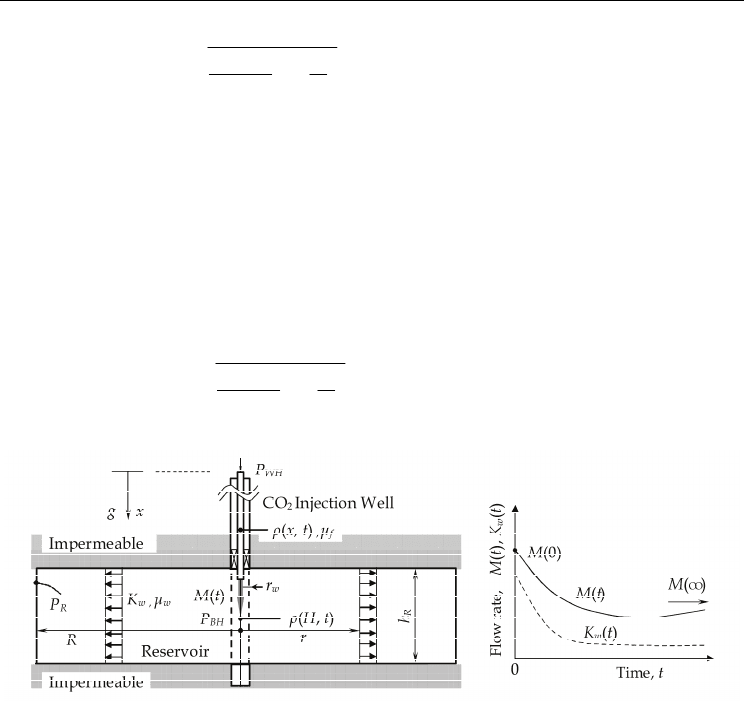
As shown in Fig. 1, a schematic radial flow model in a reservoir, such as coal seam or
aquifer, is targeted for CO
2
injection with a vertical injection well (injector). The reservoir
with radius R and thickness h
R
, is saturated with water and open with constant pressure at
its outer boundary. Assume omitting well pressure loss, the initial CO
2
mass flow rate ,
M(0), at time t = 0, that is injected into the reservoir
from its bottom hole, is equal to radial
water flow rate in the reservoir [Michael et al. (2008) and Sasaki & Akibayashi (1999)],
Two Phase Flow, Phase Change and Numerical Modeling
566
0
(0)
(0) ; (0) (0) ( ,0)
ln
2
H
BH R
BH BH WH
w
wR w
PP
M
PP gxdx
R
Kh r
ρρ
μ
π
−
==+
⋅
(1)
where ρ(x,t) and ρ
BH =
ρ(H,t) are CO
2
density in the injector and bottom hole respectively, g is
acceleration of gravity, r
w
is outer radius of the bottom hole, K
w
is reservoir permeability,
P
WH
,
P
BH
and P
R
are pressures at well head, bottom hole and outer boundary, μ
w
is water
viscosity in the reservoir, and H is length of vertical injector. The reservoir’s initial pressure
is also equal to P
R
.
After starting CO
2
injection, the CO
2
mass flow rate M(t) and bottom hole pressure P
BH
(t) are
changing with elapsed time t, since bottom hole pressure depends on CO
2
density
distribution through the injector and water is replaced with CO
2
. Therefore, flow rate after
becoming steady-state Q is given with P
BH
and CO
2
viscosity μ
f
at t = ∞.
0
()
() () ; () () (,)
ln
2
H
BH R
BH BH WH
f
wR w
PP
M
PP gxdx
R
Kh r
ρρ
μ
π
∞−
∞= ∞ ∞= ∞+ ∞
⋅
(2)
Fig. 1. Schematic radial flow model for injected CO
2
into a reservoir filled with water
Generally, CO
2
viscosity (30°C, 15MPa) is much smaller than water (roughly 1/30), thus the
flow rate increases with t. Furthermore, viscosity of supercritical CO
2
is smaller than liquid
CO
2
. On the other hand, the flow rate Q strongly depends on reservoir permeability times
height (=K
w
h
R
). Especially coal seams have relatively low permeability of order 10
-15
m
2
. It
has been reported by some projects that permeability of coal seams decreased with rough
ratio of 1/10 to 1/100 after CO
2
injection due to swelling of coal matrix by CO
2
adsorption
[Clarkson et al. (2008) and Sasaki et al. (2009)].
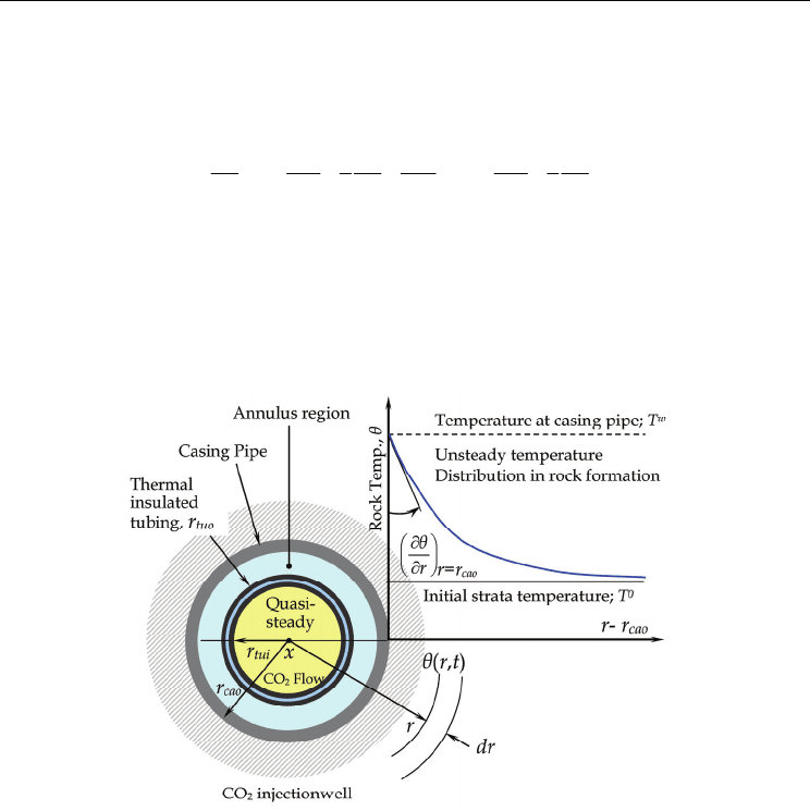
2.2 Unsteady heat conduction equation
Figure 2 shows schematic diagram of radial heat loss from a vertical injection well (injector)
that is consisting tubing pipe, casing pipes and well annulus. CO
2
is flowed down through
the tubing pipe, and injected from bottom of the well with perforated holes. The annulus
between two coaxial pipes is not used for CO
2
injection, and possibly needed to prevent heat
loss from the tubing.
Heat Transfer and Phase Change in Deep CO
2
Injector for CO
2
Geological Storage
567
In present analytical approaches, inside area of the casing pipe is assumed as quasi-steady
and outer region of the casing pipe (r ≥r
cao
) is analyzed by unsteady equation of heat
conduction. For the outer cement and rock region at a level, Fourier’s second law in
cylindrical coordinates (r, x) is expressed as;
222
222
11
rr
aa
t r rr x r rr
θθθθ θθ
∂∂∂∂ ∂∂
=++≅+
∂∂∂∂ ∂∂
(3)
where θ (°C) is rock temperature, t(s) is elapsed time, r(m) is radius, a
r
(m
2
/s) is the heat
diffusivity of rock. Heat conduction in vertical direction, x, can be omitted by comparing
with that of radial direction. Analytical solution has been presented by Starfield & Bleloch
(1983) for unsteady-state rock temperature distribution around underground airways.
Especially, they presented a method to simulate internal surface temperature using with
Biot number and elapsed time factor function of Fourier number (see section 2.7).
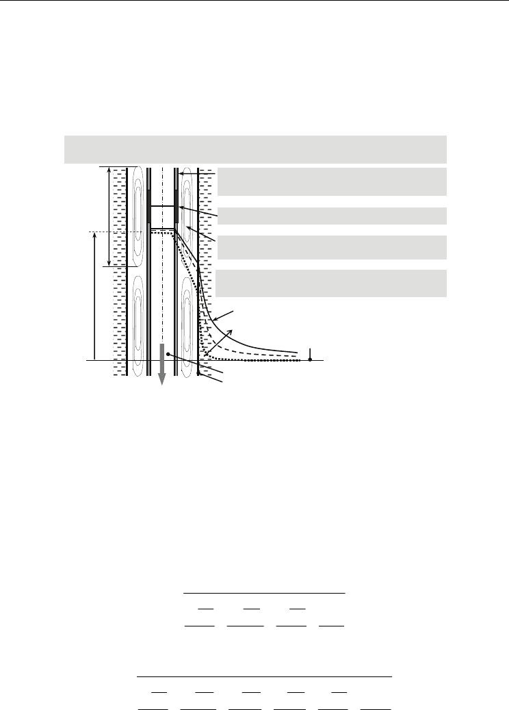
Fig. 2. Schematic diagram of radial heat flow from a vertical injection well (cross section)
2.3 Four thermal phenomena considered along CO2 injection well
Figure 3 shows a schematic of heat transfer phenomena at an injection well. Four thermal
phenomena were considered for the construction of the numerical model that is used for
predicting CO
2
temperature and pressure at the bottom hole.
1. Natural convection in the annulus, filled with N
2
or water, increases heat transfer from
tubing to casing, cement and rock formation. The heat transfer coefficient or Nusselt
number at a specific depth is determined by using a formula reported by. Choukairy et
al. (2004).
2. The thermal performance of insulated tubing containing an argon shield layer was
evaluated by considering the vertical convection flow of argon, thermal radiation
between inner surfaces of the argon layer and thermal conduction at the tubing joints.
Thermal characteristics of the insulated tubing are able to be corrected against the
Two Phase Flow, Phase Change and Numerical Modeling
568
original heat conductivity of argon gas using a number n determined by a field test and
also by well logging data (see section 2.5).
3. The CO
2
phase was determined by its specific enthalpy which can be calculated from
the pressure, temperature and heat loss along the well.
4. An unsteady analytical solution of the outer-surface temperature of casing pipe,
expressed with Eq.(1), can be applied against the elapsed time from the start of CO
2
injection.
CO
2
Temperature (liquid/supercritical)
(quasi-steady state)
In
j
ection rate:
M (t)
a)Phase chan
g
e and enthalp
y
chan
g
e of supercritical CO
2
(Pressure, Temperature,
Properties)
Casin
g
temperature:
T
W
Initial strata
temperature
T
0
h
c
CO
2
Tem
p
erature:
T
f
Tem
p
erature distribution in strata
e) Unstead
y
temperature chan
g
e with time in
rock formation
d) Natural convection heat transfer and thermal
radiation in annulus
b) Insulatin
g
characteristic of ar
g
on
g
as and
thermal radiation heat transfer
c
)
Heat conduction at
j
oints of tubin
g
p
i
p
es
Fig. 3. Heat transfer phenomena from fluid flow in injector to surrounding rock formation
2.4 Overall thermal conductivity of the quasi-steady state region of the injection well
Figure 4 shows an example of the well structure (Yubari CO
2
-ECBMR pilot-test site). CO
2
heat loss occurs during flow down to the bottom and propagates through various
cylindrical combinations of steels and fluids with various thermal properties in the well
configuration. To evaluate heat loss the overall heat conductivity that consists of
conductivities of well materials and convective heat transfer rates of fluid flows that are
contained in the well are important. Equations (4) and (5) represent single tubing and
thermally insulated tubing, respectively (Nag, 2006).
1
ln ln ln
1
cao cai tuo
cai ruo tui
Steal
f
Steal tui i
rrr
rr r
Nu r
λ
λλλα
=
+++
⋅
(4)
1
ln ln ln ln ln
1
cao cai thco thci tho
cai thco thci tho thi
Steal u
f
Steal Ar Steal thi thi
rrrrr
rr r rr
Nnr
λ
λλλλλα
=
+++++
⋅⋅
(5)