Ahsan A. Two Phase Flow, Phase Change and Numerical Modeling
Подождите немного. Документ загружается.

Heat Transfer in Nanostructures Using the Fractal Approximation of Motion
459
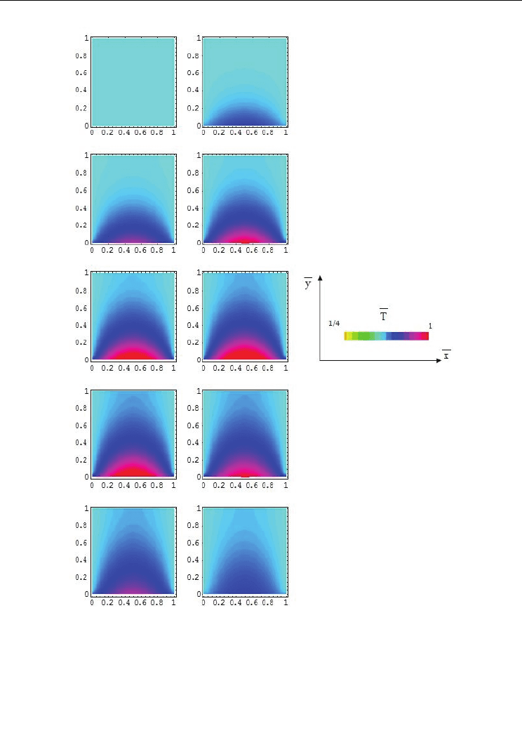
Fig. 2. a-j. Numerical 2D contour curves of the normalized temperature field in the presence
of a “wall”. Thermal field perturbation regenerates in the presence of a “wall”
4.2 Thermal anomaly of the nanofluids
The equation (28a) is implied by the Fourier type law
TkT()=− ∇j (35)
with
T()
j
the thermal current density and k the thermal conductivity.
Two Phase Flow, Phase Change and Numerical Modeling
460
Let us apply the previous formalism for the heat transfer in nanofluids, assuming the
following: (i) there are two different paths (fractal curves of fractal dimension
D
F
) of heat
flow through the “suspension”, one through the fluid particles and other through the
nanoparticles; (ii) the fractal curves are of Peano type (Nottale, 1992), which implies
D
F
=2.
The overall heat transfer rate of the system,
q, for the one-dimensional heat flow, may be
expressed as:
pff pp
fp
f
dT dT
qq q kA kA
dX dX
=+=− −
(36)
where
A, k, (dT/dX) denote the heat transfer area, the thermal conductivity and the
temperature gradient, while the subscripts
f, p denote quantities corresponding to the fluid
and the particle phase, respectively. Assuming that the fluid and the nanoparticles are in
local thermal equilibrium at each location, we can set:
fp
dT dT dT
dX dX dX
==
(37)
Now the overall heat transfer rate can be expressed as
pp
tff
ff
kA
dT
qkA
dX k A
1
=− +
(38)
We propose, using the method from (Hemanth Kumar et al., 2004), that the ratio of heat
transfer areas,
()
pf
AA, could be taken in proportion to the total surface areas of the
nanoparticles
()
p
S and the fluid species
()
f
S per unit volume of the “suspension”. Taking
both the fluid and the suspended nanoparticles to be spheres of radii
f
r and
p
r respectively,
the total surface area can be calculated as the product of the number of particles
n and the
surface area of the particle for each constituent. Denoting by
ε
the volume fraction of the
nanoparticle and by
()
1
ε
− the volume fraction of the fluid, the number of particles for the
two constituents can be calculated as :
()
f
f
p
p
n
r
n
r
3
3
1
1
4
3
1
4
3
ε
π
ε
π
=−
=
(39a,b)
The corresponding surface areas of the fluid and the nanoparticle phase are given by:
()
()
()
ff
f
pp p
p
f
Sn r
r
Sn r
r
2
2
3
41
3
4
πε
πε
==−
==
(40a,b)
Heat Transfer in Nanostructures Using the Fractal Approximation of Motion
461
Taking
f
p
p
f
S
A
SA
=
(41)
and using the previous relations, the expression for the heat transfer rate becomes:
()
pf
ff eff
fp
kr
dT dT
qkA kA
dX k r dX
1
1
ε
ε
=− + =−
−
(42)
where the effective thermal conductivity,
k
eff
is expressed as:
()
eff p f
ffp
kkr
kkr
1
1
ε
ε
=+
−
(43)
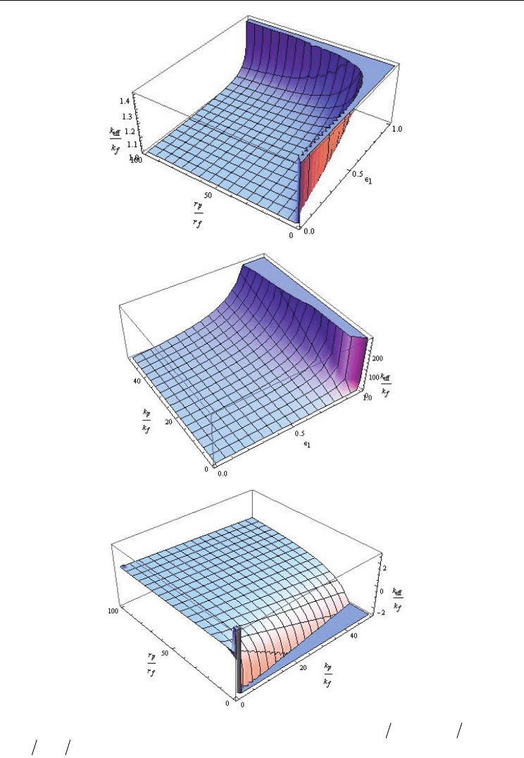
We present in Figures 3a-c the dependencies:
()
e
ff f p f p f
kkkk rrconst., ,
ε
=
(a),
()
eff f p f p f
kkkk rr,, const.
ε
=
(b) and
()
e
ff f p f p f
kkkk rr,const.,
ε
=
(c).
In the above expression, it is seen that the enhancement is directly proportional to the ratio
of the conductivities, volume fraction of the nanoparticle (for
1
ε
) and is inversely
proportional to the nanoparticle radius.
Next we determine the temperature dependence of
k
eff
. The thermal conduction of
nanoparticle based on Debye’s model is:
v
p
p
nc l
ku
ˆ
3
=
(44)
where
l is the mean free path,
v
c
ˆ
is the specific heat per particle, n is the particle
concentration and
p
u the average particle speed. Because the particle’s movement in fluid
is a Brownian one, so it can be approximate by a fractal with fractal dimension
F
D 2= , we
can use a Stokes-Einstein’s type formula for the definition of
D from Eqs. (21a, b)
B
p
kT
r
πη
D
(45)
with
B
k the Boltzmann’s constant, T the temperature and
η
the dynamic viscosity of the
fluid. For a choice of the form:
()
pp
uTrD
(46)
which implies
()
B
p
p
kT
uT
r
2
πη
(47)
the equation (44) becomes:
() ()
() ()
vB
pp rr p p p
p
TnCl kT
kkTtt kT uT uT
Tr
0
,
0000
2
0
ˆ
,
3
,
πη
== (48a-d)
Two Phase Flow, Phase Change and Numerical Modeling
462
a)
b)
c)
Fig. 3. Dependence of the effective thermal conductivity
e
ff
k on: (a)
pf
rr,
ε
; (b)
pf
kk,
ε
;
(c)
pf p f
rrkk,
ε
ε
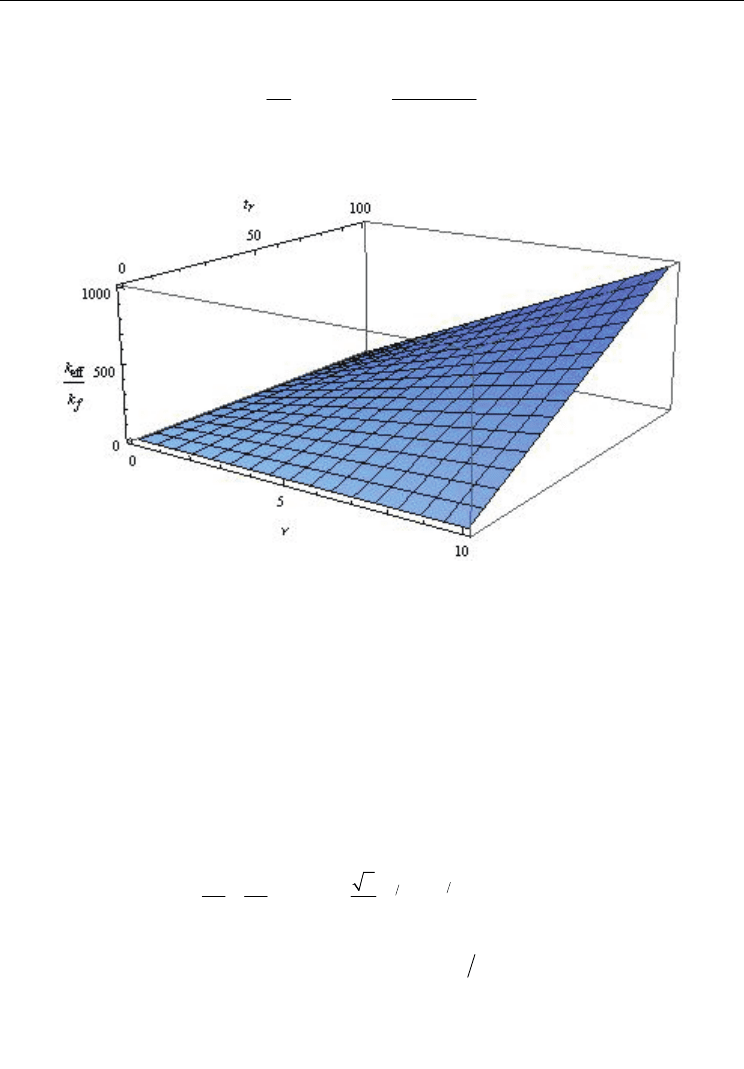
Heat Transfer in Nanostructures Using the Fractal Approximation of Motion
463
So, the dependence of
e
ff
k on the reduced temperature
r
t takes the form (see also Fig.4):
()
()
e
ff p f
r
ffp
kkTr
t
kkr
0
1,
1
ε
νν
ε
=+ =
−
(49a,b)
Obviously, Eq.(49a) it more complicated if we accept the dependence
()
r
t
ηη
= .
Fig. 4. Dependence of the effective thermal conductivity
e
ff
k on the reduced temperature
r
t and
ν
We remark that the theoretical model describes not only qualitative but also quantitative the
thermal behavior of the nanofluids experimentally observed (the increasing of the heat
transfer in nanofluids-thermal anomaly of the nanofluids) (Wang&Xu, 1999; Keblinski, 2002;
Hemanth Kumar et al., 2004).
4.3 Negative differential thermal conductance effect
Applying the fractal operator (22) in the dispersive approximation of motions to the
complex speed field (fractal function),
ˆ
V we obtain the inertial principle in the form of a
Navier-Stokes type equation:
()
()
D
F
TT
TdtT
tt
31
32
3
ˆ
2
ˆ
0
3
−
∂∂
=+⋅∇+ ∇=
∂∂
V D
(50)
with a imaginary viscosity coefficient (25).
This means that the local complex acceleration field,
t
ˆ
∂∂V , the convective term,
ˆˆ
⋅∇
VV,
and the dissipative one,
ˆ
∇
V , reciprocally compensate in any point of the fractal curve.
In the case of the irrotational motions:
ˆ
0∇× =
V (51)

Two Phase Flow, Phase Change and Numerical Modeling
464
so that the complex speed field (6) can be expressed through the gradient of a complex
scalar function Φ,
ˆ
=∇
ΦV (52)
named the scalar potential of the complex speed field.
Substituting equation (52) in equation (50) it results
() ()
()
D
F
idt
t
221
1
0
2
Φ
ΦΦ
−
∂
∇+∇− Δ=
∂
D
(53)
and by an integration, a Bernoulli type equation
() ()
()
()
D
F
idt Ft
t
221
1
2
Φ
ΦΦ
−
∂
+∇ − Δ=
∂
D
(54)
with F(t) function which depends only on time. Particularly, for
Φ
of the form:
()
()
D
F
idt
21
ln ψ
Φ
−
=−2D (55)
where
ψ
is a new complex scalar function, the equation (54) takes the form:
()
()
()
()
D
D
F
F
Ft
dt dt
t
i
21
41
2
()
2
0
ψ
ψψ
−
−
∂
Δ
∂
++=DD (56)
From here, a Schrödinger type equation result for F(t)≡0 i.e.
()
()
()
D
D
F
F
dt i dt
t
21
41
2
() 0
ψ
ψ
−
−
∂
Δ+ =
∂
DD (57)
Moreover, for the movement on fractal curves of Peano’s type, i.e. in the fractal dimension
D
F
= 2, and Compton’s length, λ, and temporal, τ, scales,
mc
0
λ
=
mc
0
2
τ
=
(58a,b)
equation (57) takes the Schrödinger standard form:
i
mt
2
0
0
2
ψ
ψ
∂
Δ+ =
∂
(59)
In the relations (58 a,b) and (59) ħ is the reduced Plank’s constant, c the speed of light on the
vacuum and m
0
the rest mass of the particle test.
Let us apply the previous mathematical model in the description of two fractal fluids
interface dynamics in the fractal dimension D
F
. Consider two fractal fluids, 1 and 2,
separated by an interface as shown in Figure 5. If the interface is thick enough so that the
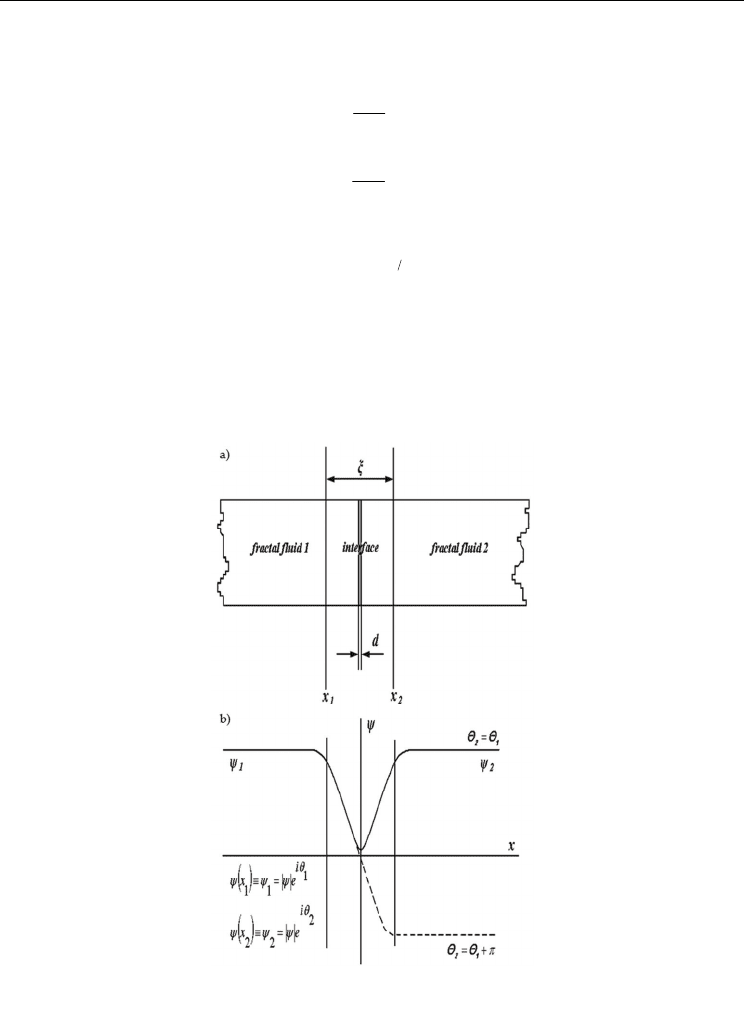
Heat Transfer in Nanostructures Using the Fractal Approximation of Motion
465
fractal fluids are “isolated” from each other, the time-dependent Schrödinger type equation
for each side is:
d
im D H
dt
1
01
1
2
ψ
ψ
=
(60)
d
im D H
dt
2
022
2
ψ
ψ
=
(61)
with
()
()
D
F
Ddt
21−
= D (62)
where
i
ψ
and H
i
, i = 1, 2 are the scalar potentials of the complex speed fields and
respectively the “Hamiltonians” on either side of the interface. We assume that a
temperature field, 2T, is applied between the two fractal fluids. If the zero point of the
temperature field is assumed to occur in the middle of the interface, the fractal fluid 1 will
be at the temperature field -T, while the fractal fluid 2 will be at the temperature field +T.
Fig. 5. Interface generated through the interaction of two fractal fluids (
d is the geometrical
thickness, before the self-structuring of the interface and
ξ
is the physical thickness, after
the self-structuring of the interface) (a) and the variation of the speed field with the fractal
coordinates (b)
Two Phase Flow, Phase Change and Numerical Modeling
466
The presence of the interface couples together the two previous Equations (60) and (61) in
the form:
d
im D T Γ
dt
1
01
2
2
ψ
α
ψψ
=+
(63)
d
im D T Γ
dt
2
021
2
ψ
α
ψψ
=− +
(64)
where α is a constant which specifies the thermal transfer type in the fractal fluid
(Vizureanu&Agop, 2007) and
Γ is the coupling constant for the scalar potentials of the
complex speed fields across the interface. Since the square of each scalar potential of the
complex speed fields is also a probability density (Notalle, 1992, 2008a, 2008b, 2007), the two
scalar potentials of the complex speed fields can be written in the form:
i
e
1
11
θ
ψρ
= (65)
i
e
2
22
θ
ψρ
= (66)
Θ
21
θθ
=− (67)
where
1
ρ
and
2
ρ
are the densities of particles in the two fractal fluids and
Θ
is the phase
difference across the interface. If the two scalar potentials of the complex speed fields (65)
and (66) are substituted in the coupled Equations (63) and (64) and the results separated into
real and imaginary parts, we obtain equations for the time dependence of the particle
densities and the phase difference:
d
dt m D
1
12
0
sin
ρΓ
ρρ
−Θ= (68)
d
dt m D
2
12
0
sin
ρΓ
ρρ
Θ
=− (69)
dΘ T
dt m D
0
α
==Ω (70)
We can specify the heat flux in terms of the difference between Equations (69) and (70)
which multiplies with ε:
()
d
j
dt
2
1
ε
ρρ
=−
(71)
It results
c
jj Θsin= (72)
where
c
j
mD
12
0
2
ε
ρρ
Γ
=
(73)

Heat Transfer in Nanostructures Using the Fractal Approximation of Motion
467
and ε is the elementary amount of energy transferred trough the interface
(Vizureanu&Agop, 2007).
Equations (70) and (72) define the thermal transport inside the interface. If the temperature
field from Equation (70) is zero, a constant heat flux of any value between
c
j− and
c
j may
flow through the junction according to the Equation (72).
We return to Equations (69), (70) and (72) and apply a constant temperature field T
0
to the
junction that is:
()
Θ tTtΘ
mD
00
0
α
=+, Θ
0
const.= (74a,b)
A variable heat flux:
()
c
jt j t Θ
00
() sin=Ω+
T
mD
00
0
α
Ω= (75 a,b)
results, although a constant temperature field is applied.
If one overlay an “alternative” temperature field over the constant temperature field:
()
Tt T T t
00
() cos=+ Ω (76)
one obtains a “frequency” modulation of the “heat flux”:
()
() ()
0
c
n
n0
n
T
jj t s t Θ
mD
T
jJ ntΘ
c
mD
0
0
0
0
0
0
sin in
1sin
α
α
+∞
=−∞
=Ω+ Ω+=
Ω
=− Ω−Ω+
Ω
const.
0
Θ =
(77a,b)
n
J is the Bessel function of integer index (Nikitov&Ouvanov, 1974). We note that, in the first
approximation, for any “arbitrary” thermal signal we can always perform a Fourier’s
decomposition (Jackson, 1991).
Since j versus T characteristic is drawn for the average thermal flux
()
jjt≈ , and since the
sine term averages to zero unless
n
0
Ω= Ω, there are spikes appearing on this characteristic
for temperature field equal to:
n
mD
Tn
0
α
=Ω
(78)
with the maximum amplitude
cn
T
jjJ
mD
0
0
max
α
=
Ω
(79)
Two Phase Flow, Phase Change and Numerical Modeling
468
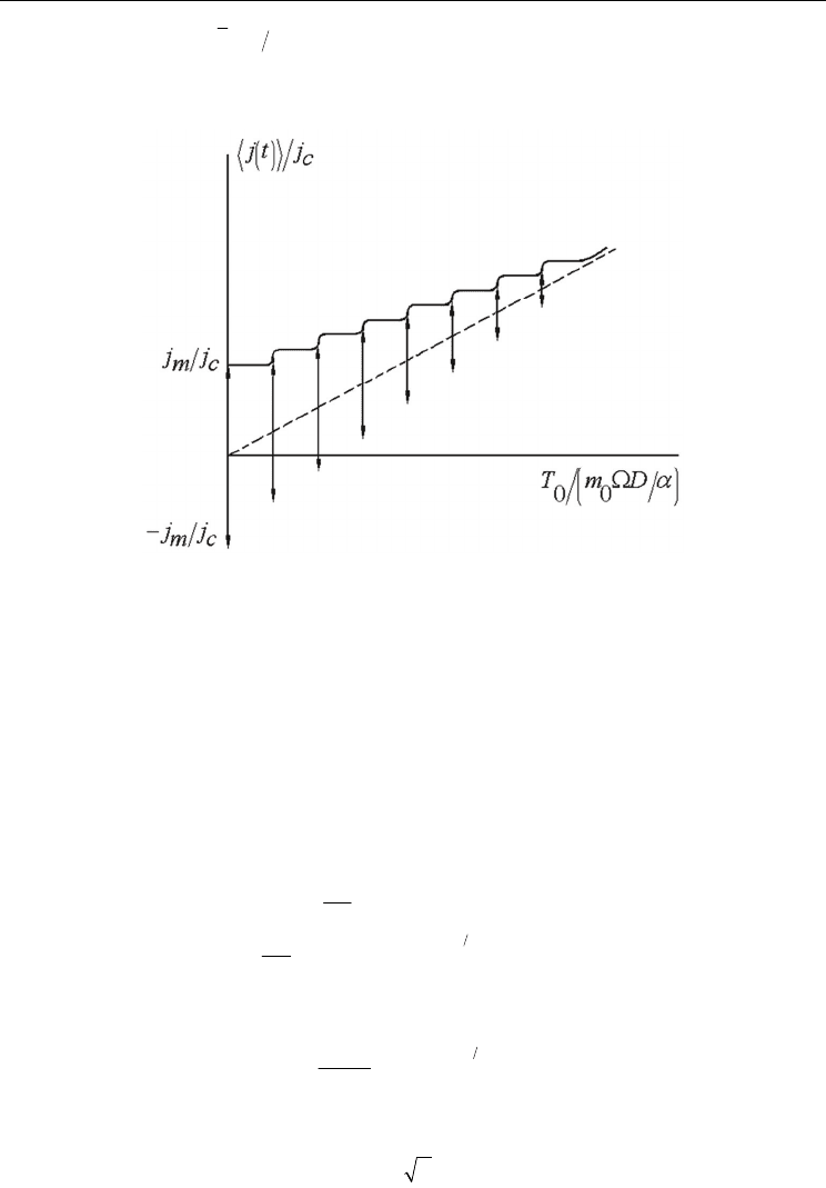
occurring for the phase Θ 2
π
= . Figure 6 shows these spikes at intervals proportional to the
thermal source “frequency” and indicates their maximum amplitude range. The value of the
heat flux can be anywhere along a particular heat flux spike, depending on the initial phase.
Fig. 6. Theoretical heat flux-temperature characteristic
It results the following:
i. The presence of the spikes in the average heat flux specifies a negative differential
thermal “conductance” which corresponds to the interface self-structuring. This is a
Josephson thermal type effect;
ii. Condition (78) corresponds to the “modulation” of the interface “oscillations” under the
influence of an external thermal signal.
4.4 Numerical simulations of the heat transfer in nanofluids
Replacing the complex speed field (6) in equation (50) and separating the real and imaginary
parts, we obtain:
()
()()
()
D
F
mm Q
t
Ddt
t
00
21
0
−
∂
+⋅∇=−∇
∂
∂
+∇ ⋅ + Δ =
∂
V
VV
U
VU V
(80a,b)
where Q is the fractal potential,
()
()
D
F
m
QmDdt
2
21
0
0
2
−
=− ∇⋅−
U
U
(81)
The explicit form of the complex speed field is given by means the expression:
iS
e
ψρ
= (82)