Ahsan A. (ed.) Evaporation, Condensation and Heat transfer
Подождите немного. Документ загружается.

Turbulent Heat Transfer i n Drag-Reducing
Channel Flow of Viscoelastic Fluid 5
In the equation above, δ
ij
is the Kronecker delta. As for a characteristic velocity, the friction
velocity (u
τ
) based on the mean pressure gradient in the streamwise direction is chosen:
u
τ
=
τ
w
ρ
=
−
δ
ρ
∂
p
∂x
.(5)
The dimensionless governing equations for an incompressible viscoelastic-fluid flow are the
continuity, momentum conservation, and constitutive equations, which can be rewritten in
tensor form based on Equations (1)–(3) as follows:
∂u
i
∂x
i
= 0, (6)
∂u
+
i
∂t
+ u
+
j
∂u
+
i
∂x
j
= −
∂p
+
∂x
i
+
β
Re
τ
∂
∂x
j
∂u
+
i
∂x
j
+
(
1 − β
)
We
τ
∂c
+
ij
∂x
j
+
∂p
+
∂x
1
δ
1i
.(7)
∂c
+
ij
∂t
+
∂u
+
k
c
+
ij
∂x
k
− c
+
ik
∂u
+
j
∂x
k
−
∂u
+
i
∂x
k
c
+
kj
+
Re
τ
We
τ
c
+
ij
− δ
ij
+ α
c
+
ik
− δ
ik
c
+
kj
− δ
kj
= 0, (8)
where i
= 1, 2, and 3 indicate the streamwise, wall-normal, and spanwise directions,
respectively. The scales used to obtain the non-dimensional variables are u
τ
and η
0
.Thelast
term on the right-hand side of Equation (7) corresponds to the mean pressure gradient driving
the flow. The superscript "
" is used to denote non-dimensional distances (e.g., y
= y/δ )and
the superscript "+" denotes the wall unit.
As suggested by Equation (7), the flow is defined by three control parameters:
Friction Reynolds number: Re
τ
=
u
τ
δ
η
0
,(9)
Weissenberg number: We
τ
=
λ
η
0
/u
2
τ
, (10)
Viscosity ratio: β
=
η
s
η
0
. (11)
Table 1 shows a summary of tested parameters for the Newtonian fluid (case 1) and the four
different viscoelastic fluids.
2.3 Governing equation for thermal field
With the calculated flow field, the instantaneous temperature of T
(
x, y, z
)
was obtained by
integrating the equation of energy conservation:
∂T
+
∂t
+ u
+
j
∂T
+
∂x
j
=
1
Re
τ
Pr
∂
2
T
+
∂x
j
2
, (12)
with non-dimensionalization by the friction temperature. In the present simulation, the
temperature difference, θ (= T
w
− T), is introduced with the following operation. As
illustrated in Fig. 1, both walls are uniformly heated with constant wall heat flux (but the
instantaneous heat flux is time-dependent), so that the statistically averaged temperature
379
Turbulent Heat Transfer in Drag-Reducing Channel Flow of Viscoelastic Fluid
6 Heat Transfer
increases linearly with respect to the x direction. Therefore, T
(
x, y, z
)
can be divided into
two parts:
T
(
x, y, z
)
=
dT
m
dx
x
− θ
(
x, y, z
)
, (13)
where T
m
is the so-called bulk mean temperature defined as follows:
T
m
=
δ
0
u
T
dy
δ
0
udy
. (14)
Here,
T
is the temperature averaged in time and in the z direction, while an overbar denotes
a quantity also averaged in the x direction. The denominator of Equation (14) corresponds
to the bulk mean velocity, u
m
=
1
0
udy
. From the heat flux balance and the present
configuration, the streamwise temperature gradient in Equation (13) becomes
dT
+
m
dx
=
1
u
+
m
. (15)
Thus, with the above transformation, we can arrange the equation for θ
(
x, y, z
)
from
Equation (12) into the following form:
∂θ
+
∂t
+ u
+
j
∂θ
+
∂x
j
=
1
Re
τ
Pr
∂
2
θ
+
∂x
j
2
+
u
u
m
. (16)
The boundary conditions for the momentum and thermal fields are:
u
i
= θ = 0, at y = 0and2δ. (17)
2.4 Simulation methodology and parameters
The current DNS is carried out by employing a finite-difference-method code solving
Equations (6)–(8) and (16), but the pressure Poisson equation was solved in Fourier space
The implicit dependence of velocity and pressure is decoupled by a fractional-step method.
Time integration was performed via the second-order Adams-Bashforth method, but the
implicit second-order Crank-Nicolson method was for the viscous terms in the wall-normal
direction. A numerical scheme with fourth-order central difference was employed in the x
and z directions, and that with second-order accuracy was applied in y. The above numerical
scheme has been extensively used to study Newtonian channel flow and turbulent heat
transfer problems (Kawamura et al., 1998; Kozuka et al., 2009).
It is well known that the addition of a constitutive equation considerably modifies the
mathematical character of the resulting system of governing equations, where accumulation
of numerical errors during time integration can cause a loss of positive definiteness and a
breakdown of the numerical calculations, which can trigger the Hadamard instability (Joseph,
1990). This instability issue in viscoelastic-flow calculations has been well documented
in the literature of steady-state viscoelastic flow simulations, and could be overcome
by improving the numerical methods (e.g., Basombrío et al., 1991; Fortin & Fortin, 1989;
Sureshkumar & Beris, 1995). Nevertheless, in view of the high non-linearity of the governing
equations, no complete mathematical theory has so far been available on the existence
and uniqueness of viscoelastic flows. In addition, the high Weissenberg-number problem
380
Evaporation, Condensation and Heat Transfer

Turbulent Heat Transfer i n Drag-Reducing
Channel Flow of Viscoelastic Fluid 7
Cases Fluid Re
τ
We
τ
β Pr Re
m
η
eff
/η
0
DR%
1 Newtonian 150 0 1.0 0.1, 1.0, 2.0 4650 1.000 —
2 viscoelastic 150 10 0.5 0.1, 1.0, 2.0 5130 0.872 20.7%
3a viscoelastic 150 30 0.5 0.1, 1.0, 2.0 7900 0.690 62.8%
3b viscoelastic 150 30 0.3 0.1, 1.0, 2.0 8860 0.518 69.5%
4 viscoelastic 150 40 0.5 0.1, 1.0, 2.0 9210 0.654 71.5%
Table 1. Given and resultant flow parameters
remains an open question (see the review papers of Bird, 1995; Keunings, 1990). The upwind
differencing scheme has been found necessary in order to ensure stable calculations. In our
simulation, the first/second-order MINMOD scheme was adapted to the convective term in
Equation (8). This scheme is a composite flux-limiter scheme (almost identical to the SOUCUP
scheme) consisting of the second-order central differencing and first-order upwind schemes
(see Zhu & Rodi, 1991). More details on this can be found by referring to (Yu & Kawaguchi,
2004).
We considered the turbulent channel flow at a fixed friction Reynolds number of Re
τ
= 150
and investigated the heat-transfer character in the drag-reducing turbulence. The fluid
rheological parameters of the Weissenberg number and the viscosity ratio are varied between
We
τ
= 0 and 40 and β = 1.0 and 0.5. Recently, the present authors’s group (Kagawa, 2008;
Tsukahara & Kawaguchi, 2011b) performed the DNSs with a Prandtl number of Pr
= 2.0. In
this work, their DNS is extended to include scalar transport with Prandtl numbers of 0.1 and
1.0. A total of 15 cases have been simulated. They are described in Table 1. In both case 3a and
case 3b, the same Weissenberg number is given to examine the effect of variance in β, while
the condition change among cases 2, 3a, and 4 is variation in We
τ
at a constant β. The mobility
factor of α
= 0.001 is fixed under all DNSs for viscoelastic fluid.
The horizontal computational domain sizes are L
x
= 12.8δ and L
z
= 6.4δ with discretizing
into 128
× 128 × 128 grid points in x, y,andz, respectively. The dimensionless grid resolutions
in the x and z directions are evenly distributed ( Δx
= 0.1, Δz = 0.05). In the wall-normal
direction, the non-uniform resolutions are stretched away from the walls, in which Δy ranges
from 0.0015 at the walls to 0.030 at the channel center. These sizes in wall units, Δx
+
, Δy
+
,
and Δz
+
, correspond to 15.0, 0.226–4.52, and 7.5, respectively. The time incremental interval,
Δt
+
,islessthan1.5× 10
−3
.
2.5 Representative mean-flow variables
In Table 1, important resultant characteristics regarding the mean flow are presented prior to
the discussion. To achieve reasonable scaling of various turbulent statistics, an effective wall
kinematic viscosity η
eff
was calculated from the proportionality between the total wall shear
stress τ
w
and the mean velocity gradient at the wall as follows:
τ
w
ρ
= η
eff
d
u
dy
y=0
. (18)
The ratio of η
eff
/η
0
in a viscoelastic flow is generally less than unity because extra stress due
to additives occurs in addition to the usual viscous stress. In a Newtonian flow, η
eff
= η
0
.As
shown in Table 1, η
eff
/η
0
decreases to near 0.5 in case 3b, which is much smaller than in the
381
Turbulent Heat Transfer in Drag-Reducing Channel Flow of Viscoelastic Fluid
8 Heat Transfer
10
0
10
1
10
2
0
10
20
30
40
u
+
= y
*
u
+
= 2.6ln y
*
+5.1
u
+
= 11.7ln y
*
–17
Yu et al. (2004)
Expt. at Re
m
=11350
Kozuka et al. (2009)
DNS at Re
τ
=180
y
*
u
+
Present
Case 1
Case 3a
Case 3b
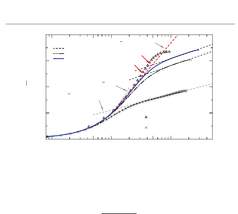
Fig. 2. Mean velocity versus wall-normal position in inner units. Viscous scalings are defined
using the effective viscosity. A red arrow indicates the thickness (upper edge) of elastic layer,
y
e
, which is defined by a crossover point of Equation (21) for the elastic layer and
Equation (22) for the turbulent core.
other cases. In case 3b, a high level of DR was obtained and found to be comparable to that in
case 4. The percentage of DR rate is defined as follows:
DR%
=
C
f
Newt
− C
f
visc
C
f
Newt
× 100%, (19)
where C
f
visc
is an obtained friction coefficient and C
f
Newt
is estimated by the empirical
correlation function,
C
f
Newt
= 0.073Re
−0.25
m
, (20)
for Newtonian turbulent channel flow (Dean, 1978) at the same value of bulk Reynolds
number Re
m
(also shown in Table 1). Better quantifications of DR%(andHTR%) were
previously proposed in the literature (Gasljevic & Matthys, 1999; Housiadas & Beris, 2004),
but will not be used here for simplicity.
3. Results and discussion
3.1 Mean velocity profile
Firstly, we shall briefly discuss the velocity field accompanied by the wall-turbulence
modulation and the drag reduction due to the fluid viscoelasticity, prior to any consideration
of the temperature field.
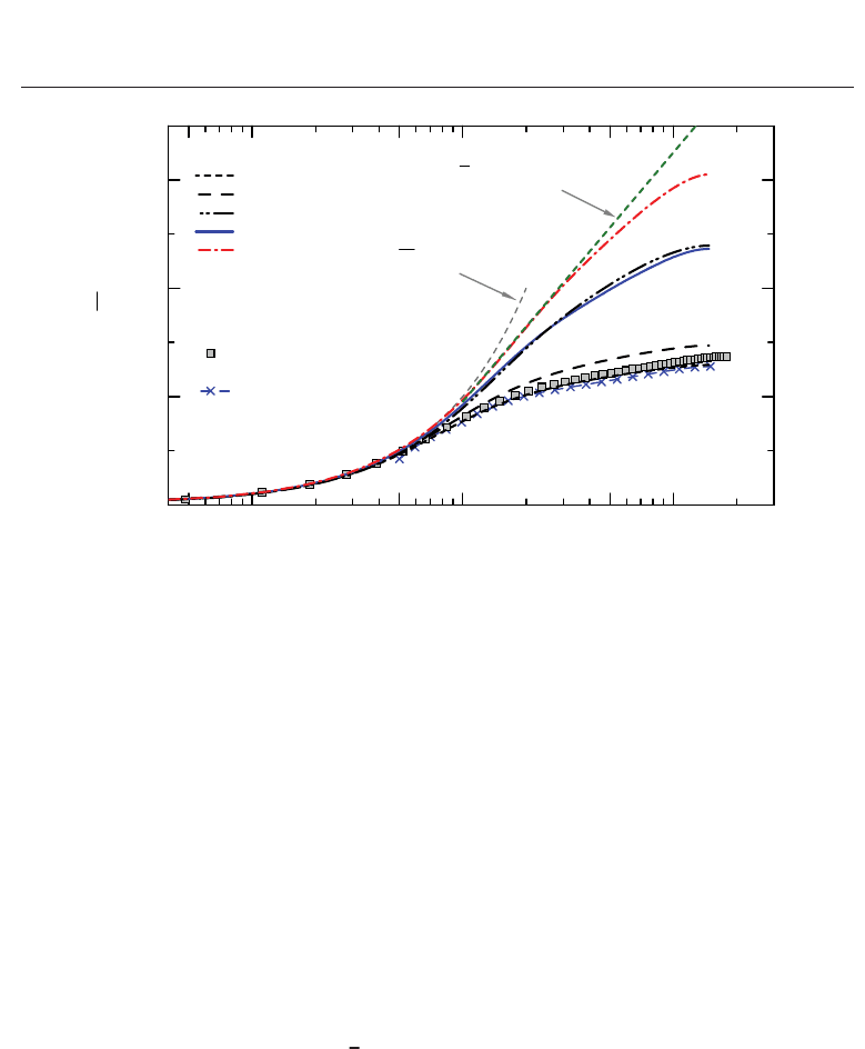
Figure 2 presents the mean velocity profile, obtained for the Newtonian flow (case 1) and two
different viscoelastic flows (cases 3a and 3b), in a semi-logarithmic coordinate. Note again
that statistics denoted by an overbar are spatially (in x and z) and temporally averaged. The
abscissa is the wall-normal distance normalized as y
∗
= yu
τ
/η
eff
.Notethaty
∗
for Newtonian
flow is equivalent to y
+
. By applying a normalization based on the effective viscosity, velocity
382
Evaporation, Condensation and Heat Transfer

Turbulent Heat Transfer i n Drag-Reducing
Channel Flow of Viscoelastic Fluid 9
profiles in the drag-reducing turbulent channel flow are scaled well, as given in the figure.
Profiles other than the shown cases have already been described (Tsukahara et al., 2011a;
Tsukahara & Kawaguchi, 2011b) and are not presented here. Also shown is the experimental
result obtained by Yu et al. (2004), where DR% of 51% was achieved using surfactant solution.
The DNS result for Newtonian flow at Re
τ
= 150 by Kozuka et al. (2009) is also included in
the figure. The present results are in qualitative agreement with their data.
As is well known, the velocity profiles in drag-reducing flow exhibit a characteristic shape
in comparison to those of Newtonian flow (Gyr & Bewersdorff, 1995; Virk, 1975). In the case
in which no DR occurs, the velocity profiles can be devided into three layers: the viscous
sublayer (0
< y
+
< 5), the buffer layer (5 < y
+
< 30), and the logarithmic layer or the
turbulent core (y
+
> 30). Virk (1971) detected an elastic layer between the viscous sublayer
and the buffer layer if DR occurred; subsequently, many experimental studies described in
the literature confirmed its appearance. The velocity profile in the elastic layer follows Virk’s
asymptote (Virk, 1971)
u
+
= 11.7 ln y
∗
− 17.0. (21)
In the turbulent core of a non-maximum drag reducing flow, the velocity follows a log law
with the Newtonian slope, but with some velocity increment B compared with the Newtonian
case, yielding the following equation:
u
+
= A ln y
∗
+ 5.5 + B. (22)
Often A is presumed to be 2.5, corresponding to the inverse of the well-known Kármán
constant (κ
= 0.4). The upward shift B of the log-law profile has been shown to be equivalent
to DR% (Gyr & Bewersdorff, 1995; Lumley, 1969). According to Dimant & Poreh (1976), the
relationship between the layer thickness and B in Equation (22) is given by
B ∝ ln
y
e
y
v
, (23)
where y
v
and y
e
are the upper bounds of the viscous and elastic sublayers, respectively. The
elastic layer successively grows with increasing DR and, at the same time, the extension of
the turbulent core decreases. When DR reaches its maximum, no turbulent core appears.
Therefore, we expect that the thickening of the elastic layer is responsible for the enhancement
of DR%. To investigate the variation in the elastic-layer thickness, we determined coefficients
A and B involved in Equation (22) using a diagnostic plotted with respect to the mean velocity
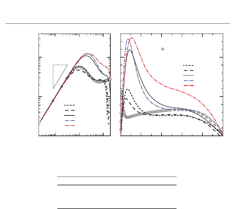
gradient. Figure 3 shows the diagnostic plotting in the form of the so-called (logarithmic)
indicator function:
ζ
≡ y
∗
du
+
dy
∗
=
⎧
⎪
⎨
⎪
⎩
y
∗
(viscous sublayer)
11.7 (elastic layer)
A or 1/ κ (logarithmic layer).
(24)
As can be seen in the left figure of Fig. 3, the viscous sublayer, in which the indicator function
has the unity gradient, ranges up to y
∗
v
= 5 for case 1. For viscoelastic cases, the viscous
sublayer is apparently thickened and its upper bound located at y
∗
v
> 10. We now employ
y
∗
v
= 11.7, at which the linear velocity profile (u
+
= y
∗
) and Equation (21) intersect, as
proposed by Virk (1975). In the elastic layer above the viscous sublayer, obtained values of
ζ for cases 3b and 4 are found to exceed 11.7, which is derived from Equation (21) of Virk’s
asymptote for polymer solution. Note that it is not surprising that surfactant solutions can
383
Turbulent Heat Transfer in Drag-Reducing Channel Flow of Viscoelastic Fluid
10 Heat Transfer
10
0
10
1
10
2
10
-1
10
0
10
1
Case 1
Case 2
Case 3a
Case 3b
Case 4
y
*
ζ
1
1
0 0.2 0.4 0.6 0.8 1
0
5
10
Present
Case 1
Case 2
Case 3a
Case 3b
Case 4
y/δ
Abe et al. (2005)
DNS at Re
τ0
= 1020
Fig. 3. Diagnostic plot, based on Equation (24), for the mean velocity profile. A profile
calculated from DNS (Abe et al., 2005) for the Newtonian flow at Re
τ
= 1020 is shown for
comparison.
Cases ABy
∗
v
–y
∗
e
y
+
v
–y
+
e
y
v
/δ–y
e
/δ ln(y
e
/y
v
)
2 2.7 1.0 11–14 9.6–12 0.064–0.081 0.18
3a 3.6 6.2 11–35 7.7–24 0.051–0.16 1.1
3b 3.4 9.7 11–48 5.7–25 0.038–0.17 1.4
Table 2. Coefficients A and B of Equation (22), and upper bounds of the viscous sublayer and
the elastic layer (y
v
and y
e
, respectively)
lead to greater DR than that predicted by the maximum DR for polymer solutions. A number
of researchers using surfactant drag-reducing additives actually reported somewhat higher
levels of DR than Virk’s asymptote (Zakin, 1996, and references therein).
The log-law profiles for both case 3a and case 3b are seemingly parallel to that of case 1, as
shown in Fig. 2. It should be noted that one issue regarding the logarithmic layer remains even
in the case of Newtonian flow, namely, the extent of the wall distance in which the log law is
believed to be valid (Örlü et al., 2010). Also plotted in Fig. 3 is ζ calculated for the Newtonian
flow at Re
τ
= 1020 on the basis of the DNS database by Abe et al. (2005). A plateau of their
ζ distribution can be found in a very narrow region of y
∗
> 30 and y/δ(= y
) < 0.2. This is
consistent with classical theory, which gives y
∗
= 30–70 as the lower limit and y/δ = 0.1–0.2
as the upper limit. Some plateau regions observed in Fig. 3 are remarkably higher than y/δ
=
0.2. Moreover, the ζ values also reveal that a log-law is strictly speaking absent, since ζ varies
continuously as y changes. Hence, the present log-law regions might not correspond to a
proper logarithmic layer, since the Reynolds number in this work is too low to find a proper
logarithmic layer.
Although conflicting to some extent in the above, we chose an average value in a plateau
region observed in y/δ
= 0.4–0.6, in order to give A specifically for estimating y
e
and B of
384
Evaporation, Condensation and Heat Transfer
Turbulent Heat Transfer i n Drag-Reducing
Channel Flow of Viscoelastic Fluid 11
y
z
x
Flow
(a) Case 3b (We
τ
= 30, β = 0.3)
y
z
x
Flow
(b) Case 4 (We
τ
= 40, β = 0.5)
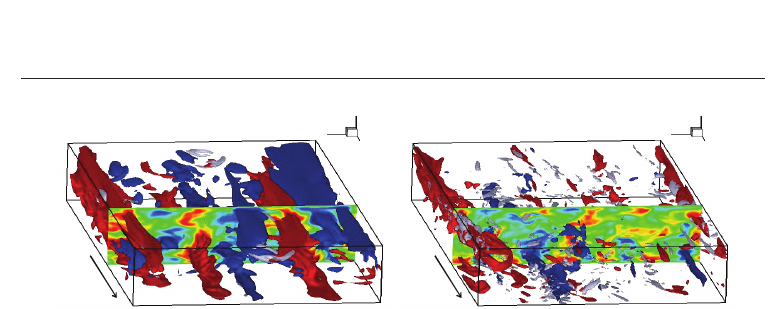
Fig. 4. Visualization of instantaneous flow field for the highly drag-reducing flows.
Iso-surfaces of streamwise velocity fluctuation are shown: red, positive; blue, negative; and
white iso-surface indicates vortex.
each viscoelastic flow. In Table 2, the calculated values A and B for three tested cases are
summarized. Also given are the extent of the elastic layer and the ratio of y
e
/y
v
. Here, we
define y
e
as the height at which the two profiles, Equation (22) and Equation (21), intercept.
In case 4, no apparent log-law (i.e., constant ζ) region was found between the elastic layer
and the core region. Similar behavior was seen in experimental results (Warholic et al., 1999;
Yu et al., 2004), where turbulent motions were suppressed and a nearly maximal level of DR
was achieved. Hence, the y
e
in case 4 could not be given explicitly from the above procedure.
The mean velocity for case 3b reveals the logarithmic profile from almost the same height as
that of case 3a, as given in Fig. 2. If normalized by the outer length scale, the upper bound of
the elastic layer for both cases is approximately y
e
/δ = 0.16. A significant difference between
cases 3a and 3b is in the magnitude of the upward shift: B in case 3b is larger than that in
case 3a, and thus the obtained DR% is larger in case 3b. The appearance of the logarithmic
layer implies a wide scale range of turbulent vortices in the flow. Therefore, the turbulent
contribution to the momentum and heat transfers is not so different between these two cases at
the same Weissenberg number. If we focus on the lower bound of the elastic layer, y
v
/δ of case
3b is found to be shifted toward the wall compared with that of case 3a: namely, the viscous
sublayer becomes thinner as β decreases. We deduce that the high DR%, which has been
obtained in case 3b, is attributable to a remarkable decrease of the effective viscosity rather
than the suppression of turbulent motions, thus inducing a thinning of the viscous sublayer by
a relative decrease of β (cf. Equation (23)). Two aspects of the coupling between fluid rheology
and amount of DR have already been identified and discussed in detail in Tsukahara et al.
(2011a): the first aspect is the reduced contribution of turbulence in a high-We
τ
flow, and the
second is the decreased effective viscosity in a low-β fluid. Through these two aspects, the DR
should be enhanced.
The instantaneous contour surface of the streamwise velocity fluctuation is visualized for
cases 3b and 4 in Figs. 4(a) and (b), respectively. Also shown are negative regions of the
second invariant of the deformation tensor (II
= ∂u
i
/∂x
j
× u
j
/∂x
i
), representing vortical
motions. As discussed above, the vortical motions remain to occur for case 3b, while they are
well damped for case 4. In the latter case, the small-scale eddies were suppressed, and the
streaks was remarkably enlarged. Suppression of these eddies reduces the Reynolds stress,
leading to a drop in the DR%.
385
Turbulent Heat Transfer in Drag-Reducing Channel Flow of Viscoelastic Fluid
12 Heat Transfer
10
0
10
1
10
2
0
20
40
60
Present
Case 1
Case 2
Case 3a
Case 3b
Case 4
Kozuka et al. (2009)
DNS at Re
τ
=180
Kader (1981)
Re
τ
=150, Pr=2.0
y
+
θ
+
θ
+
=Pr·y
+
θ
+
= 20ln y
*
–27
Fig. 5. Mean temperature profile in wall units for Prandtl number of 2.0. Also shown are a
profile for Newtonian flow at the same Prandtl number obtained by Kozuka et al. (2009), but
different Re
τ
; and one estimated by the empirical function of Kader (1981). The green broken
line is a fitting curve for case 4.
In the following sections, we analyze whether the temperature field, as well as the reduction
in heat-transfer rate, undergoes different modulation depending on these aspects.
3.2 Mean temperature profile
The dimensionless mean temperature distribution is given in Fig. 5 for Pr = 2.0, compared
with the empirical formulas of Kader (1981) for the Newtonian turbulent flow. Here, note
that the abscissa is y
+
in stead of y
∗
. The present result in case 1 (the Newtonian flow) is
in good agreement with the empirical formulas and also with the DNS data of Kozuka et al.
(2009), who performed simulations with fine grids (e.g., Δx
+
≈ 1) at high Pr up to 10. One
interesting aspect of the temperature profiles shown in Fig. 5 is that the whole cross section is
affected by the DR effects: namely, there is no noticeable log-law region in the turbulent core
(y
e
< y < δ). The thermal buffer layer (analogous to the elastic layer) for case 4 seems to be
reasonably well represented by a straight line in the semi-logarithmic coordinate, with a slope
of approximately 20 in this case, that is,
θ
+
= 20 ln y
+
− 27. (25)
We can compare our results with the asymptotic formula obtained by Gasljevic et al. (2007).
They measured temperature profiles for various kinds of polymer and surfactant solutions.
Although the Prandtl numbers in their works ranged from 6 to 9 (values for water), their
results, at least qualitatively, are comparable to ours. Their obtained slope of the logarithmic
temperature profile in the elastic layer was 69 for a relatively high concentration of polymer
solution with Pr
= 6.6. On the basis of this value, we can estimate a predicted slope of
21 for Pr
= 2, which is comparable to our result (see Fig. 5). As for a surfactant solution,
Gasljevic et al. (2007) showed a significantly sharp slope up to 210, corresponding to 65 for
386
Evaporation, Condensation and Heat Transfer
Turbulent Heat Transfer i n Drag-Reducing
Channel Flow of Viscoelastic Fluid 13
10
0
10
1
10
2
10
0
10
1
10
2
Case 1
Case 3a
Case 3b
Case 4
y
+
θ
+
/Pr
θ
+
=Pr·y
+
Pr = 0.1}
Pr = 1.0
Pr = 2.0
}
}
Case 1 (Pr = 2.0)
Case 1 (Pr = 1.0)
Fig. 6. Mean temperature profile in wall units for various Prandtl numbers with an emphasis
on the conductive-sublayer region.
Pr
= 2. They concluded that this increased slope was attributable to an apparent thickening
of the viscous sublayer. However, the viscous-sublayer thickening is still somewhat elusive,
as they also commented, because of difficulty in the near-wall measurement. It is challenging
to explain this large difference between their temperature profiles obtained with the surfactant
solution and ours. Regarding this issue, one can only conclude from the present study that
a more extensive DNS database is needed over a wide range of flow conditions and Prandtl
numbers.
The mean temperature profile is plotted again in Fig. 6 with an emphasis on the conductive
sublayer, including results at Pr
= 0.1 and 1.0. It is well known that the near-wall temperature
variation can be expanded in terms of y
+
as follows:
θ
+
= Pr · y
+
+ ··· (26)
which is clearly shown in Fig. 6. It can be seen from the figure that the conductive sublayer
penetrates more deeply into the core region with a decrease of the Prandtl number. This figure
further indicates that thickening of the conductive sublayer occurs due to DR. At Pr
= 1.0, the
conductive sublayer is evident up to y
+
≈ 15 for the viscoelastic flows but y
+
≈ 5forcase1,
suggesting that, in the elastic layer, the heat conduction should be dominant rather than the
turbulent heat transfer. Significant upward shifts of the profile for the viscoelastic flows can be
observed in the outer region, while for Pr
= 0.1 the wider conductive sublayer (up to y
+
≈ 20)
appears independently of the cases. Above the conductive layer, y
+
> 5forPr = 1–2 (y
+
> 30
for Pr
= 0.1), Weissenberg-number dependence was clearly observed. It is interesting to note
that
θ
+
of case 3b is comparable to, or slightly lower than, that of case 3a in the whole region
of the channel (see Figs. 5 and 6). As mentioned earlier, the turbulent contribution to the heat
transfer is at the same level in both cases because of the same Weissenberg number. Again,
note that, in case 3b, the viscous sublayer is relatively wide because of a small η
eff
,whichgives
387
Turbulent Heat Transfer in Drag-Reducing Channel Flow of Viscoelastic Fluid
14 Heat Transfer
Viscous
sublayer
Logarithmic
layer
Core (wake)
region
Viscous
sublayer
Log. layer
Core region
Elastic
layer
(a) Case 1: Newtonian flow (b) Case 3a: viscoelastic flow
Viscous
sublayer
Core region
Elastic
layer
Viscous
sublayer
Log. layer
Core region
Elastic
layer
Conductive
sublayer
y
y∝l
y
y∝l
y
y∝l
(d) Case 4: high We
t
y∝l
(c) Case 3b: low ß
y
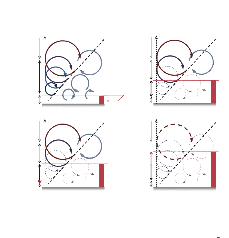
Fig. 7. Schematic view of relationship between several layers and multiscale turbulent eddies
affected by drag-reducing additives. A thick dashed line denotes typical eddy scales
proportional to the distance from the wall, on the basis of the mixing-length theory. Red bar
denotes the conductive sublayer for each relevant flow in the case of the unity Prandtl
number.
rise to enhancement of DR by as much as 69%. For these reasons, the obtained values of
θ
+
as well as the heat-transfer reduction rate (mentioned later) showed less discrepancy between
cases 3a and 3b. A similar conclusion is valid for other Prandtl numbers.
The analysis presented earlier has revealed important features of flow with drag reduction
that can be enhanced by two factors: the suppressions of turbulence by increasing We
τ
and of effective viscosity by decreasing β. It has shown that it is necessary to distinguish
between these effects for heat transfer of drag-reducing flow. Figure 7 schematically illustrates
modulated wall turbulence for each fluid case. In the Newtonian turbulent flow as given in
Fig. 7(a), we know that there is no relevant length other than the wall-normal height y in
the logarithmic layer (according to mixing length theory), and hence the energy-containing
large-scale eddies should scale roughly with y . If DR occurs by the use of additives, small
eddies near the wall can be damped because of the elasticity with a longer relaxation time
relative to the turblence time scale, and then the elastic layer appears there (see Fig. 7(b)).
The extent of the elastic layer will expand toward the wall with a lower β, while it will be
dominant far away from the wall, instead of the logarithmic layer, in the case of high We
τ
.In
388
Evaporation, Condensation and Heat Transfer