AckermannTh. (ed) Wind Power in Power Systems
Подождите немного. Документ загружается.

//INTEGRAS/KCG/P AGIN ATION/ WILEY /WPS /FINALS_1 4-12- 04/0470855088_ 27_CHA26 .3D – 601 – [587–602/16]
17.12.2004 10:50PM
g
, that has to be calcul ated as it is used as an input signal to the control system of the
VSC (see Section 26.5).
The order of the DFIG model can be reduced from six to four by omitting the stator
flux transients in Equation (26.23). Then the derivatives of the stator flux linkages will
be set to zero. Such a model is often referred to as the transient stability model or the
neglecting stator transients model (see Thiringer and Luomi, 2001; or see Section
24.4.3.3). Equation (26.23) is then simplified to:
u
s
r
¼ i
s
r
r
s
þ j
!
g
!
N
s
r
: ð26:48Þ
In power system analysis, this simplification is co mmonly used in transient and small
signal stability programs where the grid transients are neglected, too, since the power
system is modelled with phasor models, also called fundamental frequency models,
instead of instantaneous value models (Thiringer and Luomi, 2001).
26.9 Conclusions
This chapter presented a 6th-order DFIG. Special atten tion was paid to the used vector
method and the bidirectional transformations between the stator and rotor refer ence
frame.
The detailed modulation scheme of the VSC connected to the rotor of the induction
generator was not described, as it was assumed that the switching frequency of the VSC
36 36.2 36.4 36.6
0
0.5
1.0
1.5
2
2.5
Time (s)
Rotor current (p.u.) and Mode
36 36.2 36.4 36.6
305
310
315
320
325
330
335
340
Time (s)
Rotor speed ω
g
(rad/s)
Mode
Figure 26.6 Rotor current, mode of operation, and speed of the machine !
g
during a three-phase
fault in the power system
Wind Power in Power Systems 601

//INTEGRAS/KCG/P AGIN ATION/ WILEY /WPS /FINALS_1 4-12- 04/0470855088_ 27_CHA26 .3D – 602 – [587–602/16]
17.12.2004 10:50PM
is infinite. The VSC and its control was condensed and lumped together in a unique
module.
A sequencer was described, the task of which is to protect the VSC from high currents
as well as to optimise the behaviour of the system. Transient conditions require changes
of mode in the sequencer. There are three different modes generated by the sequencer.
The DFIG model was tested in a small power system that was simulated in instan ta-
neous value mode. Our model was not verified against an actual installation of a DFIG
model. Finally, we described how the order of the DFIG model can be reduced.
References
[1] Akhmatov, V. (2002) ‘Variable-speed Wind Turbines with Doubly-fed Induction Generators, Part I:
Modelling in Dynamic Simulation Tools’, Wind Engineering 26(2) 85–108.
[2] A
¨
ngquist, L. (1984) Complex Vector Representation of Three-phase Quantities. Technical report TR YTK
84-009E, ASEA Drives, Va
¨
stera
˚
s, Sweden.
[3] Centeno Lo
´
pez, E. (2000) ‘Windpower Generation Using Double-fed Asynchronous Machine’, B-EES-
0008, masters thesis, Department of Electric Power Engineering, Royal Institute of Technology, Stock-
holm, Sweden, and ABB Power Systems, Va
¨
stera
˚
s, Sweden.
[4] Fankhauser, H., Adielson, T., Aneros, K., Edris, A.-A., Lindkvist, L., Torseng, S. (1990) ‘SIMPOW – A
Digital Power System Simulator’, reprint of ABB Review 7 pp. 27–38.
[5] Kova
´
cs, P. K. (1984) Studies in Electrical and Electronic Engineering, 9: Transient Phenomena in Electrical
Machines, Elsevier, Amsterdam.
[6] Novak, P., Jovik, I., Schmidtbauer, B. (1994) ‘Modeling and Identification of Drive-system Dynamics in a
Variable-speed Wind Turbine’, in Proceedings of the Third IEEE Conference on Control Applications,
August 24–26, 1994, volume 1, Institute for Electrical and Electronic Engineers (IEEE), New York,
pp. 233–238.
[7] Thiringer, T., Luomi, L. (2001) ‘Comparison of Reduced-order Dynamic Models of Induction Machines’,
IEEE Transactions on Power Systems 16(1) 119–126.
602 High-order Models of Doubly-fed Induction Generators

//INTEGRAS/KCG/P AGIN ATION/ WILEY /WPS /FINALS_1 4-12- 04/0470855088_ 28_CHA27 .3D – 603 – [603–628/26]
17.12.2004 10:55PM
27
Full-scale Verification of
Dynamic Wind Turbine Models
Vladislav Akhmatov
Dedicated to my true friend C. E. Andersen
27.1 Introduction
The incorporation of wind power into elect ric power systems is progressing faster than
predicted. In Denmark, for example, the total installed capacity was approximately
3000 MW of grid-connected wind power in mid-2003. About 2400 MW of this capacity
is installed in Western Denmark (Jutland – Funen) and 600 MW in Eastern Denmark
(Zealand and Lolland – Falster; for more details, see Chapter 10).
In addition, the large offshore wind farm at Rødsand in Eastern Denmark started
operating in late 2003. The Rødsand wind farm comprises 72 2.3 MW fixed-speed wind
turbines (Type A) from the manufacturer Bonus Energy.
(1)
The wind farm is connected
to the transmission network of the national transmission system operator (TSO) of
Denmark. Further large offshore projects have recently gone under consideration in
Denmark, and incorporation of 400 MW offshore wind power due in the year 2008 in
Denmark has been announced.
The majority of the electricity-producing wind turbines in Denmark are Type A wind
turbines. This type is also called the Danish concept. They are scattered across the
(1)
For definitions of wind turbine Types A–D, see Section 4.2.3.
Wind Power in Power Systems Edited by T. Ackermann
Ó 2005 John Wiley & Sons, Ltd ISBN: 0-470-85508-8 (HB)

//INTEGRAS/KCG/P AGIN ATION/ WILEY /WPS /FINALS_1 4-12- 04/0470855088_ 28_CHA27 .3D – 604 – [603–628/26]
17.12.2004 10:55PM
country and are connected to the local distribution power networks. That means that
the majority of wind turbines connected to the Danish power grid are based on the same
concept as those at the Rødsand offshore wind farm.
Such a large penetration of wind power into electric power networks reduces the
amount of electric power supplied by centralised power plants and may affect the opera-
tion of the power networks. Therefore, it is important to know what consequences the
dynamic interaction between large wind farms and the power system has before the wind
farm is connected to the grid. Technical documentation has to be provided and it has to
show that the wind turbines comply with the technical specifications set by the power
system operator. The power system operator has to grant the large wind farm permission
to be connected to the grid (for more details on these issues, see Chapters 7 and 11).
It is necessary to develop and implement dynamic simulation models of wind turbines
for the existing simulation software tools that are applied in the analysis of power
system stability. The results of such analyses will be used for planning net-reinforcements
and the incorporation of dynamic reactive compensation, for revising protective relay
settings in the transmission power system and other practical arrangements, which can
be complex, expensive and time-consuming. The analysis may also take into considera-
tion economic interests of different companies and be used in the decision-making
process regarding suppliers to a large wind farm project. Therefore the analysis will focus
on the accuracy, credibility and documentation of the dynamic wind turbine models.
We use dynamic wind turbine models to investigate short-term voltage stability in the
context of connecting large amounts of wind power to the grid. The models have to
include suffici ently accurate representations of all the components of the wind turbine
construction that are relevant to such investigations. We will clarify, explain and
document the accuracy of the dynamic wind turbine models and their possible
shortcomings by validating the models. In general, the validation process should be
finished before the models are applied in the analysis of the short-term voltage stability.
Thus, validation becomes an integral part of the development of dynamic wind turbine
models and their implementation into dynamic simulation tools.
27.1.1 Background
The validations we will present here have their background in projects regarding the
incorporation of large amounts of wind power into the East Danish power system and,
more specifically, regarding the analysis of short-term voltage stability. The majority of
the small wind turbine sites in Denmark and the large offshore wind farm at Rødsand
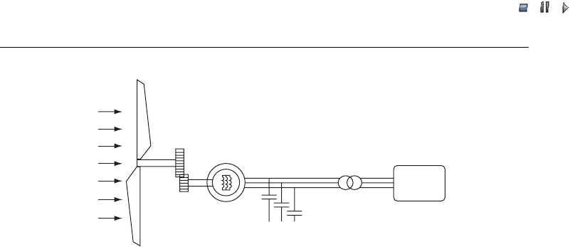
consist of Type A wind turbines (Akhmatov, 2003a). Figure 27.1 illustrates this wind
turbine concept. It shows a three-bladed rotor, a shaft system with a gearbox, and an
induction generator with a shorted rotor-circuit. These basic components need accurate
representation and validation.
We use the simulation tool Power System Simulator for Engineering (PSS/E
TM
).
(2)
When
we carried out our analysis, the dynamic simulation tool PSS/E
TM
did not contain any
(2)
PSS/E
TM
is a trademark of Shaw Power Technologies Inc. (PTI), New York, USA.
604 Full-scale Verification of Dynamic Wind Turbine Models
//INTEGRAS/KCG/P AGIN ATION/ WILEY /WPS /FINALS_1 4-12- 04/0470855088_ 28_CHA27 .3D – 605 – [603–628/26]
17.12.2004 10:55PM
model of Type A wind turbines that was sufficiently complex (Akhmatov, Knudsen and
Nielsen, 2000). Therefore, it was necessary to develop a user-written dynamic model of
Type A wind turbines to implement it into the PSS/E
TM
tool and to verify it. This project
was carried out at the Danish company NESA (Akhmatov, Knudsen and Nielsen, 2000).
The simulation tool PSS/E
TM
and modelling details are discussed briefly in Chapter 24.
This chapter describes the validation of the user-written dynami c model of Type A
wind turbines that was developed and implemented into the simulation tool PSS/E
TM
at
NESA. It includes partial validation and an example of a full-scale validation of the
dynamic wind turbine model.
27.1.2 Process of validation
When analysing short-term volta ge stability, Type A wind turbines are treated as
complex electromechanical systems (Akhmatov, Knudsen and Nielsen, 2000). The
dynamic wind turbine model contains representations of the induction generator and
the shaft system, the aerodynamic model of the turbine rotor and blade-angle control.
First, representation of the individual parts of the wind turbine construction and its
generator can be validated. At this poi nt the models of the induction generator, the shaft
system and the turbine rotor can be validated separately. This is called partial validation
and it is necessary always to specify which part of the dynamic wind turbine model is to
be validated. If the individual parts of the wind turbine model are found to be suffi-
ciently accurate, the complete model of fixed-speed wind turbines is considered to be
sufficiently accurate too. However, partial validation does not necessarily take into
account the links between different parts of the model.
Second, full-scale validation can be carried out. This also focuses on validating the
representations of the different parts of the wind turbine construction. In addition, it
validates the interaction and links between different parts of the wind turbine construc-
tion. We will illustrate full-scale validation using an example where the interaction of the
electric parameters (the machine current) and the mechanical parameters (the generator
rotor speed) are verified against measurements (Raben et al., 2003).
Wind
Wind turbine
Gearbox
Induction generator
HS
Capacitor
Grid
LS
Figure 27.1 A fixed-speed wind turbine equipped with an induction generator. Note:LS¼low
speed; HS ¼high speed. Reprinted from Akhmatov, V. Analysis of Dynamic Behaviour of
Electric Power Systems with Large Amount of Wind Power, Ph.D. thesis, Technical University
of Denmark, Kgs. Lyngby, Denmark, copyright 2003, with permission from the copyright holder
Wind Power in Power Systems 605

//INTEGRAS/KCG/P AGIN ATION/ WILEY /WPS /FINALS_1 4-12- 04/0470855088_ 28_CHA27 .3D – 606 – [603–628/26]
17.12.2004 10:55PM
We can distinguish between two types of validation processes. First, a user-written
model that is implemented into a given simulation tool can be verified against the
standardised model of the same component of the other simulation tool (Knudsen
and Akhmatov, 1999). This requires that the standardised model already be verified
and documented by the supplier of the simulation tool. Second, the user-written model
is validated against measurements. In this case, the measurements come either from
planned experiments in the field (Pedersen et al., 2003) or from transient events or
accidents that have occurred in the power network.
Probably the easiest and cheapest way of validation is to carry it out against stan-
dardised models of another simulation tool. The validating process is then characterised
by the following:
.
The cases that are simulated with the two simulation tools can be set up so that they
are as similar to each other as possible. Possible uncertainties and discrepancies
between the two cases are minimised.
.
The cases contain only those components for which representation is necessary for the
validation.
.
The network representation around the validated component is reduced.
.
The component model can be validated during simulated operational conditio ns or
during transient events, which are not always reasonable to apply in experiments
(Raben et al., 2003).
.
The results of the validation need careful interpretation.
We have to keep in mind that validation is still being carried out with use of a
simulation model, even though it is standardised in the given simulation tool. The
standardised model may still have shortcomings regarding the model assumptions and
the area of application.
An example of this is the common third-order model of induction generators, CIMTR3,
which is the standardised model of the simulation tool PSS/E
TM
. This model includes a
representation of the rotor flux transients, but it does not contain the stator flux transients
(see Chapter 24). The common third-order model is very suitable for simulating unba-
lanced, three-phased events in the power network (Pedersen et al., 2003). The disconnection
of a three-phased line is an example of such an unbalanced event. However, the common
third-order model will predict inaccurate results in the case of balanced, three-phased,
short-circuit faults with a significant voltage drop at the induction generator terminals
(Knudsen and Akhmatov, 1999). Consequently, it can be very useful to include in the
validating process other simulation tools and their standardised and validated models of
the same component. However, this requires a careful interpretation of the results.
The validation of user-written models against measur ements in the field is charac-
terised by the following:
.
Experimental work needs careful planning and preparation. Preparation includes
obtaining permission from authorities, the power system controller and the wind
turbine manufacturer (Raben et al., 2003).
.
The disturbances the wind turbines and the power network can be subjected to are
often limited. It is not always possible to obtain permission, for example, to execute
606 Full-scale Verification of Dynamic Wind Turbine Models

//INTEGRAS/KCG/P AGIN ATION/ WILEY /WPS /FINALS_1 4-12- 04/0470855088_ 28_CHA27 .3D – 607 – [603–628/26]
17.12.2004 10:55PM
experiments and subject a power system with grid-connected wind turbines to a
balanced, three-phase, short-circuit fault, even though the results of such experiments
would be valuable for validating the dynamic wind turbine model.
.
Measurements can be affected by components, control systems and parts of the power
network that are not part of the componen t to be validated. It may become necessary
to include representations of these compon ents in the network representation that is
used for the validation. Careful planning of the experimental work can reduce this
undesirable effect, though.
.
The validation is likely to be complicated by uncertainties with respect to network
configuration, the data of the components and the control systems affecting the
measurements and so on. A careful representation of the simulation case can minimise
such uncertainties.
.
The simulated and the measur ed behaviour have to be in agreement, otherwise the
model is incomplete and the interpretation of the results of the validation process is
ambiguous.
Even though there may be difficulties regarding (a) planning and executing measure-
ments in the field, (b) collecting data and (c) minimising uncertainties, the validation
results reached with the use of measurements have a high credibility. The reason for this is
that simulations aim at reproducing measured behaviour under similar conditions in
simulations. If this is not achieved, the usefulness of the simulation will be under question.
There will, however, always be discrepancies between simulated and measured beha-
viour. Such discrepancies have to be minimised by accurate modelling and by discovering
and explaining the possible sources of these discrepancies. If the validation process is
carried out accurately, such discrepancies are small and are often caused by uncertainties
in the network representation and data (Akhmatov, 2003a; Pedersen et al., 2003).
27.2 Partial Validation
In the following, we will present cases with a partial validation of the dynamic wind
turbine model. The cases are validated against simulations and measurements.
27.2.1 Induction generator model
Here we will describe the validation of the user-written model of induction generators that
is implemented in the simulation tool PSS/E
TM
at NESA. This is a transient fifth-order
model (i.e. it contains a representation of the fundamental frequency transients of the
machine current). The validation is carried out against simulations with the standar-
dised model of the tool Matlab/Simulink
TM
.
(3)
The simulated sequence is a three-phase,
short-circuit fault that lasts 100 ms. We chose to validate the user-written model in
PSS/E
TM
against simulations with the standardised model of induction generators of
Matlab/Simulink
TM
for the following reasons:
(3)
Matlab/Simulink
TM
is a trademark of The MathWorks Inc; Natrick, USA.
Wind Power in Power Systems 607
//INTEGRAS/KCG/P AGIN ATION/ WILEY /WPS /FINALS_1 4-12- 04/0470855088_ 28_CHA27 .3D – 608 – [603–628/26]
17.12.2004 10:55PM
.
A balanced, three-phase, short-circuit fault is a common transient event that has been
analysed in investigations on transient voltage stability (Knudsen and Akhmatov,
1999). Therefore it is necessary to ensure that the user-written model in the tool PSS/
E
TM
gives a sufficiently accurate response for this kind of fault.
.
It can be difficult to obtain permission to carry out an experiment with such a
disturbance in the grid because this is a serious incident.
.
The tool Matlab/Simulink
TM
is applied and recognised worldwide.
.
The tool Matlab/Simulink
TM
contains the standardised and verified model of induction
generators, which is a three-phase, physical representation. The model is suitable for the
simulation of balanced as well as unbalanced transient events in the power network.
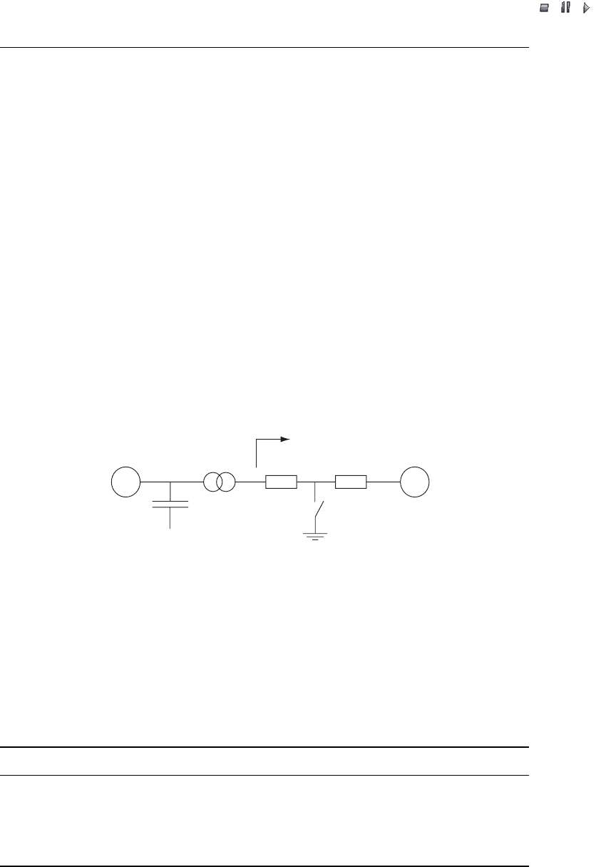
The validation process is based on a simple network equivalent. It contains an
induction generator connected to an infinite bus through a 0.7/10 kV transformer and
a line with an impedance corresponding to the short-circuit ratio (SCR) of 6.7. Figure
27.2 shows the network equivalent. The network equivalent models are implemented
both in the simulation tool PSS/ E
TM
(the positive-sequence equ ivalent) and the tool
Matlab/Simulink
TM
(the three-phase representation). The implementation for each
simulation tool is as similar as possible. The induction generator works at the rated
operation point and supplies 2 MW. Table 27.1 includes the data.
P
G
=2MW
S
T
=2.7 MW
e
R
=1%, e
X
=6%
C
K
= 0.5 MVAR
IG
0.7/10
kV
SCR = 6.7
Z /2
Z /2
100
ms
Infinite bus
1
Figure 27.2 Model of a network equivalent with an induction generator (IG). Note:SCR¼ short-
circuit ratio; P
G
¼generator electric power; C
K
¼no-load compensation; S
T
¼transformer power
capacity; e
R
¼real part of transformer impedance; e
x
¼imaginary part of transformer impedance.
Reprinted from Akhmatov, V. Analysis of Dynamic Behaviour of Electric Power Systems with
Large Amount of Wind Power, Ph.D. thesis, Technical University of Denmark, Kgs. Lyngby,
Denmark, copyright 2003, with permission from the copyright holder
Table 27.1 Data of a 2 MW induction generator. Reprinted from Akhmatov, V. Analysis of
Dynamic Behaviour of Electric Power Systems with Large Amount of Wind Power, Ph.D. thesis,
Technical University of Denmark, kgs. Lyngby, Denmark, copyright 2003, with permission from
the copyright holder
Parameter Value Parameter Value
Rated power (MW) 2 Stator resistance (p.u.) 0.048
Rated voltage (v) 690 Stator reactance (p.u.) 0.075
Rated frequency (Hz) 50 Magnetising reactance (p.u.) 3.80
Rated slip 0.02 Rotor resistance (p.u.) 0.018
Generator rotor inertia (s) 0.5 Rotor reactance (p.u.) 0.12
608 Full-scale Verification of Dynamic Wind Turbine Models
//INTEGRAS/KCG/P AGIN ATION/ WILEY /WPS /FINALS_1 4-12- 04/0470855088_ 28_CHA27 .3D – 609 – [603–628/26]
17.12.2004 10:55PM
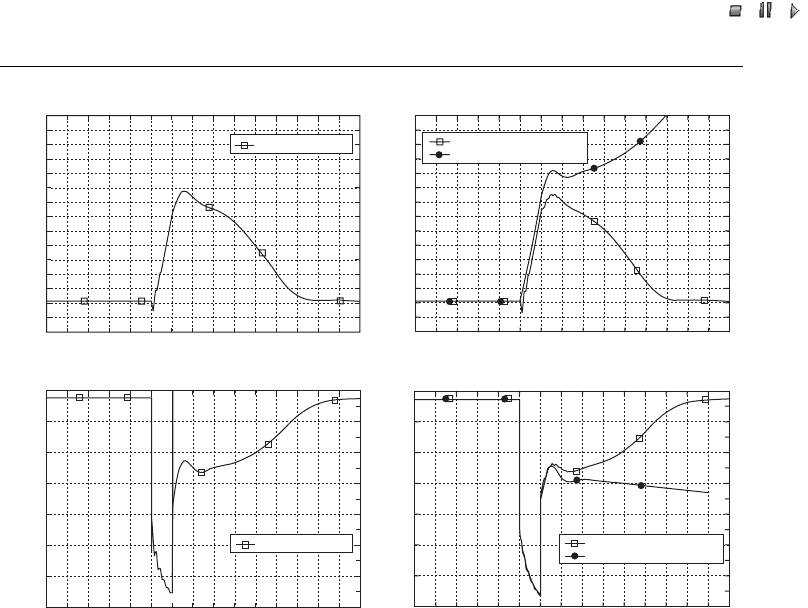
Figure 27.3 illustrates the simulated behaviour of the voltage and the generator rotor
speed, which is applied to validate the transient fifth-order model of induction genera-
tors. For a comparison, the behaviour computed with the use of a common third-order
model in the tool PSS/E
TM
(neglecting fundamental frequency transients in the machine
current) is plotted in the same figure.
As expected (Knudsen and Akhmatov, 1999), the simulated results of the transient
fifth-order model of induction generators in the tool PSS/E
TM
are in agreement with the
results of the standardised model of the tool Matlab/Simulink
TM
. The common third-
order model of induction generators predicts overpessimistic results with respect to
maintaining short-term voltage stability, for the following reasons:
.
The common third-order model predicts more overspeeding of the induction genera-
tor during the grid fault, compared with the results of the fifth-order model. An
explanation of this phenomenon is given in Chapter 24.
.
The mechanical parameter, which is the generator slip, and the electric parameters of
the induction generator are strongly coupled. If the prediction of the overspeeding is
too high, the prediction of the reactive absorption will be too high as well.
(b)
184
182
180
178
176
174
172
170
Speed, (rad/s)
168
166
164
162
160
158
186
156
0.6 0.7 0.8 0.9 1.0 1.1 1.2
Time (s)
1.3 1.4 1.5 1.6 1.7 1.8 1.9
0.5
2
PSS/E
TM
fifth-order model
PSS/E
TM
third-order model
184
182
180
178
176
174
172
170
Speed, (rad/s)
168
166
164
162
160
158
186
156
(a)
0.6 0.7 0.8 0.9 1.0 1.1 1.2
Time (s)
1.3 1.4 1.5 1.6 1.7 1.8 1.90.5 2
Matlab/Simulink
TM
(c)
600
500
400
Voltage (V)
300
200
100
700
0
0.6 0.7 0.8 0.9 1.0 1.1 1.2
Time (s)
1.3 1.4 1.5 1.6 1.7 1.8 1.9
0.5
2
Matlab/Simulink
TM
(d)
600
500
400
Voltage (V)
300
200
100
700
0
0.6 0.7 0.8 0.9 1.0 1.1 1.2
Time (s)
1.3 1.4 1.5 1.6 1.7 1.8 1.9
0.5
2
PSS/E
TM
fifth-order model
PSS/E
TM
third-order model
Figure 27.3 Simulated behaviour of the generator rotor speed: (a) using Matlab/Simulink
TM
and
(b) using PSS/E
TM
. The terminal (RMS phase–phase) voltage: using (c) Matlab/Simulink
TM
, and
(d) using PSS/E
TM
. Reprinted from Akhmatov, V. Analysis of Dynamic Behaviour of Electric
Power Systems with Large Amount of Wind Power, Ph.D. thesis, Technical University of
Denmark, Kgs. Lyngby, Denmark, copyright 2003, with permission from the copyright holder
Wind Power in Power Systems 609

//INTEGRAS/KCG/P AGIN ATION/ WILEY /WPS /FINALS_1 4-12- 04/0470855088_ 28_CHA27 .3D – 610 – [603–628/26]
17.12.2004 10:55PM
.
Consequently, the common third-order model of induction generators predicts a slower
voltage re-establishing after the grid fault than does the transient fifth-order model.
.
In this particular case, the common third-order model predicts voltage instability,
whereas according to the transient fifth-order model of induction generators the
voltage is re-established.
Knudsen and I reached the same conclusion when validating against the standardised
induction generator model of the Alternative Transient Program (ATP) simulation tool
(Knudsen and Akhmatov, 1999). Chapter 24 briefly describes the ATP tool. This was
also the first time that the validity and accuracy of the common third-order model of
induction generators were questioned as to whether the model should be used in the
analysis of short-term voltage stability.
Wind turbine generators are equipped with protective relays. This means that several
electrical and mechanical parameters are monitored, and if one of the monitored
parameters exceeds its respective relay settings the wind turbine generators will be
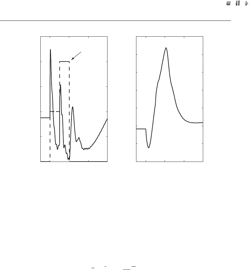
disconnected. One of the monitored parameters is the machine current. Figure 27.4
shows the computed behaviour of the machine current during the grid fault. As can be
seen, the machine currents computed with the transient fifth-order model in the tool
PSS/E
TM
and with the standardised model of the tool Matlab/Simulink
TM
are in
agreement. The machine current computed with the common third-order model in the
tool PSS/E
TM
does not coincide with the result of the tool Matlab/Simulink
TM
.
This needs further explanation. The transient fifth-order model takes the following
into account when computing the behaviour of the machine current:
.
A three-phased, short-circuit fault is a balanced transient event, meaning that the fault
occurs at the same moment in all three phases. The phase current can be characterised
by the DC offset, and the current phasor contains the fundamental frequency transi-
ents. The computed current behaviour during the faulting time shows this.
.
The short-circuit fault is cleared sep arately in each phase of the faulted three-phased
line. This happens when the phase-currents pass zero in the respective phases. The
fault clearance is therefore an unbalanced event. It does not initiate the DC offset in
the pha se currents, and the fundamental frequency transients in the current phasor
are eliminated after the fault is cleared.
.
The standardised model of induction generators in the tool Matlab/Simulink
TM
automatically takes this behaviour into account because Matlab/Simulink
TM
operates
with three-phased representations of electric machines and power networks.
.
The transient fifth-order model of induction generators in the tool PSS/E
TM
is
adapted to this behaviour. This is necessa ry because the simulation tool PSS/E
TM
operates with positive-sequence equivalents of power network models.
.
Additionally, the phase current behaviour is plotted. This phase current is modelled in
Matlab/Simulink
TM
and is included here in order to demonstrate that the current phasor
follows the behaviour of the magnitude of the phase current with developed DC offset.
This observation is important for the validating process described in Section 27.3.
According to the current behaviour shown in Figure 27.4, the common third-order
model of induction generat ors underpredicts values of the machine current during the
610 Full-scale Verification of Dynamic Wind Turbine Models