AckermannTh. (ed) Wind Power in Power Systems
Подождите немного. Документ загружается.


//INTEGRAS/KCG/P AGIN ATION/ WILEY /WPS /FINALS_1 4-12- 04/0470855088_ 27_CHA26 .3D – 591 – [587–602/16]
17.12.2004 10:50PM
We can introduce subscripts to refer S(t) to the two different frames as follows:
.
S
s
(t) is the space vector referred to the stator reference frame;
.
S
r
(t) is the space vector referred to the rotor reference frame.
In order to decrease the number of indices, the time-dependence (t) is included for all
quantities but is not indexed in subsequent formulae.
The coordinate transformation of
S from rotor to stator reference frame can be
expressed as follows:
S
s
¼ S
r
e
j
g
¼ S
rd
þ j S
rq
e
j
g
; ð26:2Þ
where
g
is the angle between the two reference frames, which in our application is the
rotor angle of the machine. S
rd
is the real part of S
r
, and S
rq
is the imaginary part of S
r
.
The above transform ation is necessary if the connection of the machine is to be
described for the power system. The power system requires all quantities to be expressed
in the stator reference frame.
Identifying real and imaginary parts in Equation (26.2), we obtain:
S
sd
¼ S
rd
cos
g
S
rq
sin
g
; ð26:3Þ
S
sq
¼ S
rq
cos
g
þ S
rd
sin
g
: ð26:4Þ
Furthermore, the inverse transformation is required in order to go from the stator to the
rotor reference frame. The equations for this transformation are as follows:
S
r
¼ S
s
e
j
g
; ð26:5Þ
identifying real and imaginary parts in Equation (26.5), we obtain:
S
rd
¼ S
sd
cos
g
þ S
sq
sin
g
; ð26:6Þ
S
rq
¼ S
sq
cos
g
S
sd
sin
g
: ð26:7Þ
This coordinate transformation will be carried out for all stator quantities (i.e. for the
voltages, currents and fluxes) as all equations will be formulated and solved in the rotor-
fixed reference frame.
The projection of the space vectors over the phase axis has to coincide with the
corresponding phase quantities. This requirement results in the following relationship
between the phase and dq components for the rotor:
S
ra
¼ Re½S
r
¼S
rd
; ð26:8 Þ
S
rb
¼ Re S
r
e
j2=3
hi
¼
1
2
S
rd
þ
ffiffiffi
3
p
2
S
rq
; ð26 :9Þ
S
rc
¼ Re S
r
e
j2=3
hi
¼
1
2
S
rd
ffiffiffi
3
p
2
S
rq
: ð26:10Þ
It should be noted that the real axis (i.e. the d axis) is collinear to the phase a winding
axis. From the equations above, it can be derived that the space vector can be expressed
Wind Power in Power Systems 591

//INTEGRAS/KCG/P AGIN ATION/ WILEY /WPS /FINALS_1 4-12- 04/0470855088_ 27_CHA26 .3D – 592 – [587–602/16]
17.12.2004 10:50PM
as a function of phase quantities. For the rotor, we arrive at the following relationship
between dq and phase components:
S
rd
þ j S
rq
¼
2
3
S
ra
þ
1
2
þ j
ffiffiffi
3
p
2
!
S
rb
þ
1
2
j
ffiffiffi
3
p
2
!
S
rc
"#
: ð26:11Þ
Identifying real and imaginary parts in Equation (26.11), we obtain:
S
rd
¼
1
3
ð2S
ra
S
rb
S
rc
Þ; ð26:12Þ
S
rq
¼
1
ffiffiffi
3
p
S
rb
S
rc
ðÞ: ð26:13Þ
From Equations (26.12) and (26.13) it can be concluded that instantaneous three-phase
quantities [real-valued S
a
(t), S
b
(t)andS
c
(t)] can be transformed into a unique space
vector with real and imaginary parts S
d
(t) and S
q
(t), respectively.
Note that the complex magnitudes described above are different from the complex
magnitudes used in the so-called j! method. The j! method assumes the complex
magnitudes to rotate with constant speed, !, whereas here ! is allowed to vary freely.
26.4.2 Notation of quantities
In the following, we use the subscript italic s for quantities that are expressed in the stator
reference frame and the subscript italic r for quantities that are expressed in the rotor
reference frame. Superscript upright s represents the index of a stator quantity and super-
script upright r represents the index of a rotor quantity. Therefore,
u
s
r
represents the stator
voltage in the rotor reference frame, and
u
s
s
represents the stator voltage in the stator
reference frame. The notation
u represents a complex quantity, in this case a voltage.
26.4.3 Voltage equations of the machine
The stator voltage u
s
s
, referred to the stator frame is:
u
s
s
¼ i
s
s
r
s
þ
d
s
s
dt
; ð26:14Þ
where
i
s
s
is the complex stator current and
s
s
is the complex stator flux. r
s
is the stator
winding resistance.
The coordinate transformation of any quantity be tween the rotor reference frame and
the stator reference frame was derived in Equation (26.2). By applying this equation to
the three complex quantities in Equat ion (26.14), we trans form the equation from the
stator reference frame to the rotor reference frame. The result is:
i
s
s
¼ i
s
r
e
j
g
; ð26:15Þ
u
s
s
¼ u
s
r
e
j
g
; ð26:16Þ
s
s
¼
s
r
e
j
g
: ð26:17Þ
592 High-order Models of Doubly-fed Induction Generators

//INTEGRAS/KCG/P AGIN ATION/ WILEY /WPS /FINALS_1 4-12- 04/0470855088_ 27_CHA26 .3D – 593 – [587–602/16]
17.12.2004 10:50PM
Substituting Equations (26.15) – (26.17) into Equation (26.14), we get
u
s
r
e
j
g
¼ i
s
r
e
j
g
r
s
þ
d
s
r
e
j
g
dt
: ð26:18Þ
The last term of Equation (26.18) is expanded as follows:
d
s
r
e
j
g
dt
¼ e
j
g
d
s
r
dt
þ
s
r
de
j
g
dt
¼ e
j
g
d
s
r
dt
þ
s
r
dj
g
dt
e
j
g
¼ e
j
g
d
s
r
dt
þ j!
g
s
r
e
j
g
;
ð26:19Þ
where !
g
is the speed of the machine. Inserting Equation (26.19) into Equation (26.18),
we obtain:
u
s
r
e
j
g
¼ i
s
r
e
j
g
r
s
þ e
j
g
d
s
r
dt
þ j !
g
s
r
e
j
g
: ð26:20Þ
By multiplying both sides of Equation (26.20) by e
j
g
, we arrive at the final stator
voltage equation in the rotor-fixed coordinate frame:
u
s
r
¼ i
s
r
r
s
þ
d
s
r
dt
þ j !
g
s
r
: ð26:21Þ
The voltage equation for the rotor circuit in the rotor reference frame can be directly
expressed as
u
r
r
¼ i
r
r
r
r
þ
d
r
r
dt
; ð26:22Þ
where
u
r
r
is the complex rotor voltage; i
r
r
is the complex rotor current;
r
r
is the complex
rotor flux; and r
r
is the rotor winding resistance.
26.4.3.1 Per unit system of the machine
So far, all equations have been written and deduced using real values of the variables and
parameters involved. In general, it is very useful to work in a per unit (p.u.) system, which
will be developed in this section. In order to arrive at a per unit system, we have to define a
base system first (see also Section 24.5). There is a number of base systems from which we
can choose. We will, however, use peak phase voltage and peak phase current as the base
values. The other base values can be calculated from these two base values, as shown in
Table 26.1. It has to be stressed that the base power, S
base
, is the three-phase power of the
induction generator, S
N
, (where a subscript N indicates the nominal value).
Equations (26.21) and (26.22) in p.u. of the machine base are:
u
s
r
¼ i
s
r
r
s
þ
1
!
N
d
s
r
dt
þ j
!
g
!
N
s
r
; ð26:23Þ
Wind Power in Power Systems 593
//INTEGRAS/KCG/P AGIN ATION/ WILEY /WPS /FINALS_1 4-12- 04/0470855088_ 27_CHA26 .3D – 594 – [587–602/16]
17.12.2004 10:50PM
u
r
r
¼ i
r
r
r
r
þ
1
!
N
d
r
r
dt
: ð26:24Þ
Note that the speed of the machine !
g
in Equation (26.23) is in [radians per second].
In our equations, machine speed, !
g
, as well as turbine speed, !
m
, will be measured in
physical units. The angular speed, !
N
, in Equations (26.23) and (26.24) is equal to 2f
N
,
where f
N
is the power frequency (e.g. 50 Hz).
26.4.4 Flux equations of the machine
In order to solve the system of equations for the induction generator it is necessary in
addition to formulate equations representing the relationship between currents and
fluxes. In the following stator flux equation, the stator current and the stator flux are
referred to the rotor reference frame:
s
r
¼ i
s
r
x
s
þ i
r
r
x
m
; ð26:25Þ
where x
s
is the stator self-reactance, equal to
x
s
¼ x
s
l
þ x
m
; ð26:26Þ
and where x
s
l
is the leakage reactance of the stator and x
m
is the mutual reactance
between the stator and rotor windings. Equation (26.25) is given in p.u.
It can be shown that the values of the reactances and inductances coincide if they are
given in p.u. Therefore, the reactances in Equation (26.25) can be replaced with the
inductances given on the same p.u. base.
Table 26.1 Per unit bases
Quantity Expression
U
base
(kV) U
base
¼ U
N
ffiffi
2
p
ffiffi
3
p
I
base
(kA) I
base
¼
S
N
U
N
ffiffi
2
p
ffiffi
3
p
S
base
(MVA) S
base
¼ S
N
¼
2
3
U
base
I
base
Z
base
() Z
base
¼
U
base
I
base
¼
U
2
N
S
N
!
base
(rad/s) !
base
¼ !
N
¼ 2f
N
T
base
(MWs) T
base
¼
P
base
!
base
¼
S
base
!
base
¼
S
N
!
N
base
(Wb)
base
¼
U
base
!
base
¼
U
N
!
N
ffiffi
2
p
ffiffi
3
p
Note: U ¼voltage; I ¼current; S ¼apparent power; Z ¼impedance;
! ¼ rotational speed; T ¼torque; ¼ flux; subscript ‘base’ indicates
the base value for the per unit system; subscript N indicates the
nominal value; U
N
is the nominal root mean square (RMS) value of
the phase-to-phase voltage of the machine.
594 High-order Models of Doubly-fed Induction Generators

//INTEGRAS/KCG/P AGIN ATION/ WILEY /WPS /FINALS_1 4-12- 04/0470855088_ 27_CHA26 .3D – 595 – [587–602/16]
17.12.2004 10:50PM
In the following rotor flux equation, the stator current is referred to the rotor frame:
r
r
¼ i
s
r
x
m
þ i
r
r
x
r
; ð26:27Þ
where x
m
is the mutual reactance between the stator and rotor windings and x
r
is the
rotor self-reactance, which is equal to
x
r
¼ x
r
l
þ x
m
; ð26:28 Þ
and where x
r
l
is the leakage reactance of the rotor.
By combining Equation (26.25) with Equation (26.27), the stator and rotor currents
can be expressed as functions of stator and rotor fluxes:
i
s
r
¼
s
r
x
m
x
r
r
r
.
x
s
1
x
2
m
x
s
x
r
; ð26:29Þ
i
r
r
¼
r
r
x
m
x
s
s
r
.
x
r
1
x
2
m
x
s
x
r
; ð26:30Þ
and, by introducing the total leakage factor, , given by
¼ 1
x
2
m
x
s
x
r
; ð26:31Þ
we can rewrite Equations (26.29) and (26.30) as
i
s
r
¼
s
r
x
m
x
r
r
r
1
x
s
; ð26:32Þ
i
r
r
¼
r
r
x
m
x
s
s
r
1
x
r
: ð26:33Þ
Equations (26.32) and (26.33) describe the currents of the machine as functions of the
stator and rotor fluxes. All quantities are in the rotor reference frame.
26.4.5 Mechanical equations of the ma chine
There are two different mechanical bodies in the system we want to represent – the
induction generator and the wind turbine. This section contains the mechanical equa-
tions of the induction generator.
The mechanical equations of the induction generator can be represented as follows :
d!
g
dt
¼
!
N
2H
g
ðT
EL
þ T
SHAFT
Þ; ð26:34Þ
d
g
dt
¼ !
g
; ð26:35Þ
where T
EL
is the elect rical torque produced by the induction generator; T
SHAFT
is the
incoming torque from the shaft connecting the induction generator with the wind
turbine; and H
g
is the inertia constant of the inducti on generator. The angle
g
is the
Wind Power in Power Systems 595

//INTEGRAS/KCG/P AGIN ATION/ WILEY /WPS /FINALS_1 4-12- 04/0470855088_ 27_CHA26 .3D – 596 – [587–602/16]
17.12.2004 10:50PM
machine angle, and !
g
is the speed of the induction generator. All quantities, except for
the machine speed, !
g
, are given in p.u.
The expression for the electrical torque in physical units is
T
EL
¼
3
2
Im
s
r
i
s
r
hi
: ð26:36Þ
The derivation of Equation (26.36) is not included here; for further details, see Kova
´
cs,
1984. The asterisk indicates the complex conjugate of the flux, . Using Equation
(26.32) for the stator current in the rotor reference frame,
i
s
r
, the equation for the
electrical torque can be rewritten as
T
EL
¼
3
2
Im
s
r
x
s
s
r
x
m
x
r
r
r
"#
¼
3x
m
2x
s
x
r
ð
s
rq
r
rd
s
rd
r
rq
Þ;
ð26:37Þ
where real and imaginary parts of the stator and rotor fluxes are shown in parentheses in
the final expression. Their relation to the complex stator and rotor fluxes is as follows:
s
r
¼
s
rd
þ j
s
rq
; ð26:38Þ
r
r
¼
r
rd
þ j
r
rq
: ð26:39Þ
Expressed in the p.u. system, the equation for the electrical torque, Equation (26.37), is
T
EL
¼
x
m
x
s
x
r
ð
s
rq
r
rd
s
rd
r
rq
Þ; ð26:40Þ
where the reactances, total leakage factor, fluxes and torque are given in p.u. of the
machine ratings.
The incoming torque from the shaft to the induction generator, T
SHAFT
, in Equation
(26.34), consists of the two terms T
TORSION
and T
DAMPING
:
T
SHAFT
¼ T
TORSION
þ T
DAMPING
: ð26:41Þ
Equation (26.41) represents a drive-train system, where T
TORSION
represents the elasti-
city of the shaft and T
DAMPING
represents the damping torque of the shaft (see Novak,
Jovile and Schmidtbauer, 1994 and Akhmatov, 2002).
T
TORSION
is expressed as a function of the angle of the wind turbine,
m
, and the angle
of the machine,
g
,as
T
TORSION
¼ Kð
m
g
Þ; ð26:42Þ
where K is the shaft torsion constant (p.u. torque/rad); that is, it is the effective shaft
stiffness.
T
DAMPING
is related to the speed of the wind turbine, !
m
, and the speed of the
machine, !
g
, as follows:
T
DAMPING
¼ Dð!
m
!
g
Þ; ð26:43Þ
596 High-order Models of Doubly-fed Induction Generators

//INTEGRAS/KCG/P AGIN ATION/ WILEY /WPS /FINALS_1 4-12- 04/0470855088_ 27_CHA26 .3D – 597 – [587–602/16]
17.12.2004 10:50PM
where D is the shaft damping constant [p.u. torque/(rad/sec)] and represents the damp-
ing torque in both the wind turbine and the induction generator.
It is important to note that the speed of the machine, !
g
, and the speed of the wind
turbine, !
m
, are measured in radians per second and that the angle of the machine,
g
,
and the angle of the wind turbine,
m
, are measured in radians.
26.4.6 Mechanical equations of the wind turbine
The mechanical equations of the wind turbine are represented by the following two
differential equations:
d!
m
dt
¼
!
N
2H
m
ðT
MECH
T
SHAFT
Þ; ð26:44Þ
d
m
dt
¼ !
m
; ð26:45Þ
where T
MECH
is the mechanical torque produced by the wind turbine; T
SHAFT
is the
torque from the shaft co nnecting the induction generato r with the wind turbine [see
Equation (26.41)]; and H
m
is the inertia constant of the turbine. The angle
m
represents
the position of the wind turbine, and !
m
is the speed of the wind turbine. All quantities
except !
m
and
m
are given in p.u.
In this chapter, we assume that the mechanical torque, T
MECH
, produced by the wind
turbine is constant. However, the constant T
MECH
can be changed to a varying T
MECH
,
as described in Section 24.3.1
The equations of the machine given in this section (Section 26.4) can also be found in
Centeno, 2000.
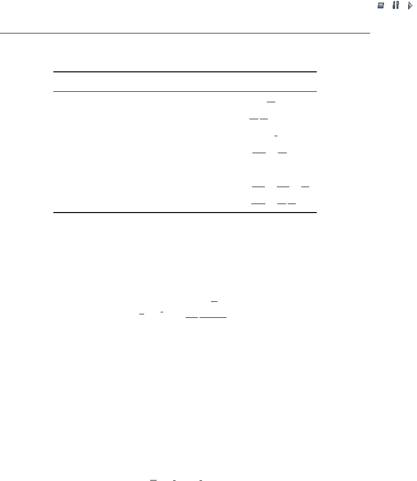
26.5 Voltage Source Converter
It is assumed that the converters in Figure 26.1 are arranged in a VSC. In this chapter,
we will not implement the detailed modulation scheme but, rather, assume that the
switching frequency is infinite. If the detailed modulation scheme were implemented it
would slow down the simulations significantly, as each switching operation of the
converter would be han dled by the simulator as a separate event. The switching opera-
tions of the converters can be neglected without significantly affecting the result.
In this chapter, the VSC and its control is condensed and lumped together in a unique
module. Therefore, the voltage that the voltage source control impresses onto the rotor of
the machine is represented as a direct output of the voltage source converter control, (
u
r
r
in
Figure 26.3). In spite of this simplification, we take into account the limitations in the voltage
generation that the converter imposes. These limitations will be implemented as limitations
to the voltage and torque controllers (U-reg and T-reg, respectively, in Figure 26.3).
The strategy used for the converter control is field-oriented control. The input signals
to the VSC are:
.
the stator voltage in the stator reference frame of the machine, u
s
s
;
.
the speed of the machine, !
g
;
Wind Power in Power Systems 597
//INTEGRAS/KCG/P AGIN ATION/ WILEY /WPS /FINALS_1 4-12- 04/0470855088_ 27_CHA26 .3D – 598 – [587–602/16]
17.12.2004 10:50PM
.
the angle of the machine,
g
;
.
the electrical torque of the machine, T
EL
.
Figure 26.3 shows the input parameters to the converter control: the stator winding
resistance, r
s
; the stator self-reactance, x
s
; the rotor winding resistance r
r
; the rotor self-
reactance, x
r
; and the mutual reactance between the stator and rotor windings x
m
; !
N
is equal to 2f
N
,wheref
N
is the power frequency (e.g. 50 Hz). The input parameters x
s
and x
r
were defined in Equations (26.26) and (26.28), respectively. The constant
was defined in Equation (26.31). The following two reference values are also fed into
the VSC: !
gref
and u
s
ref
, each set by the user to a constant value throughout the simulation.
RFC
s
in Figure 26.3 is the stator flux in the rotor flux coordinate system RFC. V
RFC
r
is a
complex quantity which real part is the output signal from the voltage controller V
RFC
rd
and its imaginary part is the output signal from the torque controller V
RFC
rq
.
RFC
r
in
Figure 26.3 is the rotor flux in the RFC system, a real quantity, is the rotor flux angle in
the rotor coordinate system, T
Erefwlim
is a torque reference which is the output signal from
the speed control !-reg. In Figure 26.3 s represents the Laplace operator.
The constants
s
and
r
in Figure 26.3 are defined as follows:
s
¼
x
s
r
s
!
N
; ð26:46Þ
r
¼
x
r
r
r
!
N
: ð26:47Þ
u
s
v
s
T
Erefwlim
T
EL
θ
g
ω
gref
ω
g
–s
(1–σ)r
s
σx
m
(1–σ)r
r
σx
m
–r
ψ
s
–s
ψ
s
RFC
ψ
s
– RFC
u
r
– r
u
r
RFC
–
–
ψ
RFC
V
rd
RFC
V
rq
V
r
s
u
ref
–s
+
+
+
+
ρ
+
–
+
–
+
–
1+σ
τ
s
s
σx
s
r
s
1
1+
σ
τ
r
s
σ
x
r
r
r
1
e
–
j
(θ
g
+ ρ)
e
j
(θ
g
+ ρ)
+
++
–
e
jρ
U-reg
ω -reg
T
-reg
–s
u
s
j
–
·
·
ω
n
s
s
r
–RFC
ψ
r
Figure 26.3 Control system configuration for the voltage source converter; for definitions of
variables, see section 26.5
598 High-order Models of Doubly-fed Induction Generators

//INTEGRAS/KCG/P AGIN ATION/ WILEY /WPS /FINALS_1 4-12- 04/0470855088_ 27_CHA26 .3D – 599 – [587–602/16]
17.12.2004 10:50PM
The speed, voltage and torque controllers – !-reg, U-reg, and T-reg, respectively – are
modelled as PI controllers (proportional–integral controllers).
26.6 Sequencer
The sequencer is a module that handles the different modes of operation of the system
that consists of the DFIG, the wind turbine, the VSC and its control. The need for such
a sequencer arises from the fact that whenever there is a fault in the interconnected
power system, the system of the DFIG must be able to handle the resulting high currents
without causing any damage to the equipment. Another reason for having different
modes is that the system has to recover from a fault as soon as possible in order to
remain in phase. The sequencer basically controls the rotor current level and the stator
voltage level and sets the current mode of operati on.
The aim of the sequencer is to protect the VSC from high currents as well as to optimise the
behaviour of the system. The changes of mode are required during transient conditions. There
are three different modes, with mode 0 corresponding to the mode for normal operation.
If the rotor current exceeds 2 p.u., the VSC has to be disconnected because it cannot
resist such a high current. Therefore, the rotor is short-circuited during such an event. If
the machine works as a short-circuited machine, the system operates in mode 1. If the
machine works in mode 1 and the stator voltage magnitude has been greater than 0.3 p.u.
for 100 ms, the system switches to mode 2. During mode 2, the machine is still short-
circuited, but additional resistances are connected into the rotor circuit. In that case, the
equivalent rotor resistance is 0.05 p.u., which forces the rotor current to decrease.
Finally, if the system works in mode 2 and the stator voltage level has exceeded
0.85 p.u. for 100 ms and the rotor current has been lower than 2 p.u. for 100 ms, the
system returns to normal operation (i.e. mode 0). Once the system has returned to
normal operation the machine first tries to get magnetised and then starts producing
torque. That is done by setting the torque reference to 0 during 400 ms, once the
disturbance has been cleared.
The left-hand side of Figure 26.6 (page 601) depicts the modes of operation during a
simulation.
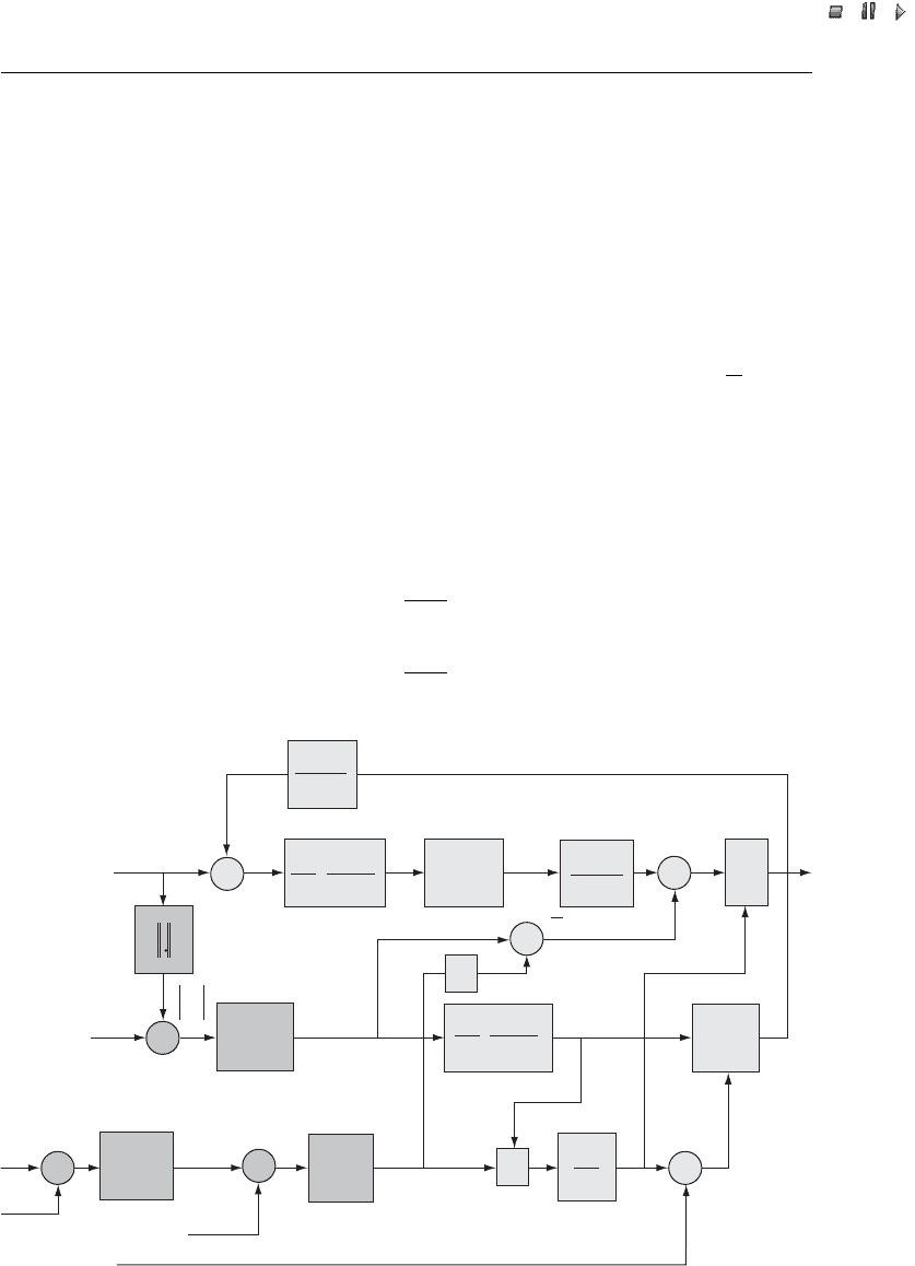
26.7 Simulation of the Doubly-fed Induction Generator
In this section we will test the setup of the DFIG. The machine is incorporated into a
small power system where it is connected to an infinite bus via a line impedance,
Z,of0:06 þ j0:60 (). In the power system, there will be a three-phase fault at t ¼36 s at
30% of the full distance from the infinite bus (see Figure 26.4). The three-phase fault has a fault
resistance, R
fault
,of0:30 (). The power system is modelled in instantaneous value mode.
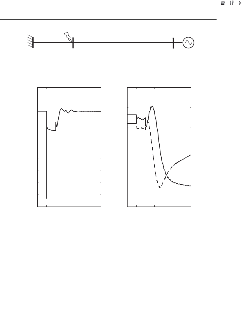
Prior to the fault, the DFIG operates at nominal speed. In Figure 26.5, the terminal
voltage is shown on the left-hand side and the stator fluxes
sd
and
sq
are shown on the
right-hand side.
In Figure 26.6, the rotor current and the mode of operation is shown on the left-hand
side and the speed of the machine, !
g
, on the right-hand side. From Figure 26.6 we can
see that the rotor is short-circuited (mode of operation equal to 1) approximately
Wind Power in Power Systems 599
//INTEGRAS/KCG/P AGIN ATION/ WILEY /WPS /FINALS_1 4-12- 04/0470855088_ 27_CHA26 .3D – 600 – [587–602/16]
17.12.2004 10:50PM
between 36.0 < t < 36.1 (s). When the mode of operation is equal to 2, between
36.1 < t < 36.2 (s), the rotor is still short-circuited but the rotor current is slowly
decreasing as additional resistances are switched into the rotor circuit.
After a few seconds, the DFIG model returns to its initial state. However, this is not
shown in Figures 26.5 and 26.6.
26.8 Reducing the Order of the Doubly-fed Induction Generator
Different models are available to simulate the behaviour of the DFIG under different
conditions. The machine described in Section 26.4 is a 6th-order model, as the model
contains the following six state variables:
s
rd
,
s
rq
,
r
rd
,
r
rq
, !
g
and
g
.
s
rd
and
s
rq
are
the real and imaginary parts of the stator flux
s
r
, and
r
rd
and
r
rq
are the real and
imaginary parts of the rotor flux
r
r
, as shown in Equations (26.38) and (26. 39).
The 6th-order model developed in this chapter is an extension of the 5th-order model
described in Thiringer and Luomi (2001). The extension consists of the machine angle,
Infinite bus Fault
DFIG bus
Figure 26.4 Test system for the doubly-fed induction generator (DFIG)
36 36.2 36.4 36.6
0.2
0.3
0.4
0.5
0.6
0.7
0.8
0.9
1.0
1.1
1.2
Time (s)
Terminal voltage (p.u.)
36 36.2 36.4 36.6
–1.5
–1.0
–0.5
0
0.5
1
1.5
Time (s)
ψ
sd
and ψ
sq
(p.u.)
Figure 26.5 Terminal voltage and stator fluxes
sd
and
sq
of the doubly-fed induction generator
(DFIG) during a three-phase fault in the power system
600 High-order Models of Doubly-fed Induction Generators