AckermannTh. (ed) Wind Power in Power Systems
Подождите немного. Документ загружается.


//INTEGRAS/KCG/PAGINATION/WILEY/WPS/FINALS_14-12-04/0470855088_06_CHA05.3D – 81 – [79–96/18] 20.12.2004
7:30PM
5.2.1 Rated data
The rated data of a wind turbine, P
n
, Q
n
, S
n
and I
n
are defined as follows:
.
Rated power, P
n
, is the maximum continuous electric output power which a wind
turbine is designed to achieve under normal operating conditions.
.
Rated reactive power, Q
n
, is the reactive power from the wind turbine while operating
at rated power and nominal voltage and frequency.
.
Rated apparent power, S
n
, is the apparent power from the wind turbine while
operating at rated power and nominal voltage and frequency.
.
Rated current, I
n
, is the current from the wind turbine while operating at rated power
and nominal voltage and frequency.
5.2.2 Maximum permitted power
The 10-minute average output power of a wind turbine may, depending on the wind
turbine design, exceed its rated value. Thus, the maximum permitted power parameter,
P
mc
, serves to provide a clear definition of the maximum 10-minute average power that
can be expected from the wind turbine.
Wind turbines with active control of output power (i.e. by blade pitching and/or speed
control) typically provide P
mc
¼ P
n
.
Wind turbines with passive control of output power (i.e. fixed-speed, stall-controlled
wind turbines) are commonly set up with P
mc
some 20 % higher than P
n
.
5.2.3 Maximum measured power
The maximum measured power, P
60
, measured as a 60-second average value, and P
0:2
,
measured as 0.2-second average value, serves two purposes. First, P
60
and P
0:2
should be
considered in conjunction with relay protection settings; second, they may be of par-
ticular relevance for the operation of wind turbines on isolated grids.
A variable-speed wind turbine may typically provide P
0:2
¼ P
60
¼ P
n
, whereas for
fixed-speed wind turbines, stall or pitch controlled, P
0:2
will commonly be larger than P
n
.
5.2.4 Reactive power
The reactive power of the wind turbine is to be specif ied in a table as 10-minute average
values as a function of the 10-minute average output power for 0.10 %, ..., 90%,
100 % of the rated power. Also, the reactive power at P
mc
, P
60
and P
0:2
has to be
specified.
Wind turbines with an induction generator connected directly to the grid consume
reactive power as a function of the output active power. The consumption is typically
compensated by capacitors that may be connected in steps (see also Chapters 4 and 19).
Wind turbines employing modern frequency converters are commonly capable of
controlling the reactive power to zero or possibly of supplying or consuming reactive
power according to needs, although this is limited by the size of the converter.
Wind Power in Power Systems 81
//INTEGRAS/KCG/PAGINATION/WILEY/WPS/FINALS_14-12-04/0470855088_06_CHA05.3D – 82 – [79–96/18] 20.12.2004
7:30PM
5.2.5 Flicker coefficient
The power fluctuations from wind turbines during continuous operation cause corres-
ponding voltage fluctuations on the grid. The amplitude of the voltage fluctuations will
depend not only on the grid strength relative to the amplitude of the power fluctuations
but also on the network impedance phase angle and the power factor of the wind
turbine.
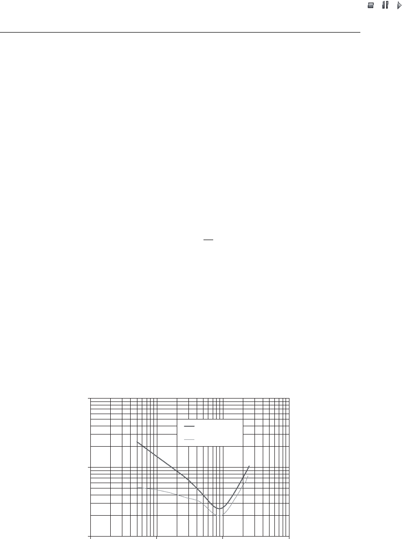
Voltage fluctuations may cause annoying changes in the luminance from lamps. The
impression of this is denoted ‘flicker’ and may be measured by using a flickermeter as
described in IEC 61000-4-15 (IEC, 1997). The flickermeter takes voltage as input and
gives the flicker severity as output. As can be seen from the normalised response of the
flickermeter in Figure 5.1, even a quite small voltage fluctuation can be annoying if it
persists at certain frequencies.
The flicker coefficient is a normalised measure of the maximum flicker emission (99th
percentile) from a wind turbine during continuous operation:
c
k
; v
a
ðÞ¼P
st
S
k
S
n
; ð5:1Þ
where
P
st
is the flicker emission from the wind turbine,
S
n
is the rated apparent power of the wind turbine,
S
k
is the short-circuit apparent power of the grid.
The flicker coeff icient has to be given as the 99th percentile for specified values of the
network impedance phase angle (30
,50
,70
and 85
) and annu al average wind speed
(6 m/s, 7.5 m/s, 8.5 m/s and 10 m/s).
0.1
1
10
0.1 1 10 100
Frequency (Hz)
Voltage fluctuation (%)
sinusoidal
rectangular
Figure 5.1 Normalised flickermeter response for voltage fluctuations (peak-to-peak)
82 Power Quality Standards

//INTEGRAS/KCG/PAGINATION/WILEY/WPS/FINALS_14-12-04/0470855088_06_CHA05.3D – 83 – [79–96/18] 20.12.2004
7:30PM
Variable-speed wind turbines are commonly expected to yield fairly low flicker
coefficients, whereas values for fixed-speed wind turbines may range from average
(stall-controlled) to high (pitch-controlled); see also Figure 16.6 (page 353) and Figure
16.7 (page 354).
5.2.6 Maximum number of wind turbine switching operations
The following cases of switching operations are relevant as these may cause significant
voltage variations:
.
wind turbine startup at cut-in wind speed ;
.
wind turbine startup at rated wind speed;
.
the worst case of switching between generators (applicable only to wind turbi nes with
more than one generator or a generator with multiple windings).
The acceptance of switching operations depends not only on their impact on the grid
voltage but also on how often these may occur. Hence, the maximum number of the
above-specified switching operations within a 10-minute period, N
10
, and a 2-hour
period, N
120
, should be stated. N
10
and N
120
may be governed by modern wind turbine
control system settings.
5.2.7 Flicker step factor
The flicker step factor is a normalised measure of the flicker emission due to a single
switching operation of a wind turbine:
k
f
ð
k
Þ¼
1
130
S
k
S
n
P
st
T
0:31
p
; ð5:2Þ
where
T
p
is the duration of the voltage variation due to the switching operation;
P
st
is the flicker emission from the wind turbine;
S
n
is the rated apparent power of the wind turbine;
S
k
is the short-circuit apparent power of the grid.
The flicker step factor has to be given for specified values of the network impedance
phase angle (30
,50
,70
and 85
) and for the specified types of switching operations
(see Section 5.2.6).
Variable-speed wind turbines are commonly expected to yield fairly low flicker step
factors, whereas values for fixed-speed wind turbi nes may range from average (pitch-
controlled) to high (stall-controlled).
Wind Power in Power Systems 83

//INTEGRAS/KCG/PAGINATION/WILEY/WPS/FINALS_14-12-04/0470855088_06_CHA05.3D – 84 – [79–96/18] 20.12.2004
7:30PM
5.2.8 Voltage change factor
The voltage change factor is a normalised measure of the voltage change caused by a
single switching operation of a wind turbine:
k
u
ð
k
Þ¼
ffiffiffi
3
p
U
max
U
min
U
n
S
k
S
n
; ð5:3Þ
where
U
min
and U
max
are the minimum and maximum voltage [root mean square (RMS)
phase-to-neutral] due to the switching;
U
n
is the nominal phase-to-phase voltage;
S
n
is the rated apparent power of the wind turbine;
S
k
is the short-circuit apparent power of the grid.
The voltage change factor has to be given for specified values of the network
impedance phase angle (30
,50
,70
and 85
) and for the specified cases of switching
operations (see Secti on 5.2.6).
The voltage ch ange factor k
u
is similar to the in-rush current factor, k
i
being the ratio
between the maximum inrush current and the rated current, though k
u
is a function of the
network impedance phase angle. The highest value of k
u
will be numerically close to k
i
.
Variable-speed wind turbines are commonly expected to yield fairly low voltage
change factors, whereas values for fixed-speed wind turbines may range from average
(pitch-controlled) to high (stall-controlled).
5.2.9 Harmonic currents
The emission of harmonic currents during the continuous operation of a wind turbine
with a power electronic converter has to be stated. The individual harmonic currents will
be given as 10-minute average data for each harmonic order up the 50th at the output
power giving the maximum individ ual harmonic current, and, further, the maximum
total harmonic current distortion also has to be stated.
Harmonic emissions have been reported from a few installations of wind turbines
with induction generators but without power electronic convert ers. There is, however,
no agreed procedure for measurements of harmonic emissions from induction machines,
and there is no known instance of customer annoyance or damage to equipment as a
result of harmonic emissions from such wind turbines. IEC 61400-21 therefore does not
require measurements of harmonic emissions from such wind turbines.
5.2.10 Summary power quality characteristics for various wind turbine types
Typical power quality characteristics for various wind turbine types are summarised in
Table 5.1. The actual parameter values are specific to the wind turbine type and variations
are to be expected depending on the detailed solutions applied by the manufacturer.
Hence, accurate assessment requires manufacturer-specific data to be collected.
84 Power Quality Standards

//INTEGRAS/KCG/PAGINATION/WILEY/WPS/FINALS_14-12-04/0470855088_06_CHA05.3D – 85 – [79–96/18] 20.12.2004
7:30PM
5.3 Impact on Voltage Quality
This section gives a brief description of the impact that wind turbines may have on the
voltage quality. The application of wind turbi ne power quality characteristics to deter-
mine the impact of wind turbines on voltage quality is explained through a case study
considering a 5 750 kW wind farm on a 22 kV distribution feeder. The case study
further demonstrates that possible voltage quality problems resulting from a wind
turbine installation in many cases may be overcome simply by selecting an appropriate
wind turbine type and/or by adjusting wind turbine control pa rameters.
5.3.1 General
Ideally, the voltage should form a perfect sinusoidal curve with constant frequency and
amplitude. However, in any real-life power system, grid-connected appliances will cause
Table 5.1 Typical power quality characteristics for various wind turbine types
Quantity Wind turbine type
a
A0 A1 A2 B C D
Maximum permitted
power, P
mc
P
mc
> P
n
P
mc
¼ P
n
P
mc
¼ P
n
P
mc
¼ P
n
P
mc
¼ P
n
P
mc
¼ P
n
Maximum measured power
60 s average, P
60
P
60
> P
n
P
60
¼ P
n
P
60
¼ P
n
P
60
¼ P
n
P
60
¼ P
n
P
60
¼ P
n
Maximum measured power
0.2 s average, P
0.2
P
0:2
> P
n
P
0:2
> P
n
P
0:2
> P
n
P
0:2
¼ P
n
P
0:2
¼ P
n
P
0:2
¼ P
n
Reactive power, Q
b
f(P) f(P) f (P) f(P)0 0
Flicker coefficient, c(
k
, v
a
) Average High Average Low Low Low
Maximum number of
switching operations in
a 10 min period, N
10
CPS CPS CPS CPS CPS CPS
Maximum number of
switching operations in
a 2 h period, N
120
CPS CPS CPS CPS CPS CPS
Flicker step factor, k
f
(
k
) High Average Average Low Low Low
Flicker change factor, k
u
(
k
) High Average Average Low Low Low
Maximum harmonic current, I
h
c
————LowLow
a
For more information turbine types A0, A1, A2, B, C and D, see Section 4.2.3.
b
Regarding wind turbine types A and B, use of capacitors that are connected in steps or power
electronics may lead to enhanced control of reactive power. Regarding wind turbine types C and
D, assuming use of modern frequency converters, the reactive power may be fully controlled
within the rating of the converter.
c
This is relevant only for wind turbine types C and D. The indicated low emission of harmonic
currents is based on the assumption that modern frequency converters are used.
— Not applicable
Note: CPS ¼ control parameter setting.
Wind Power in Power Systems 85
//INTEGRAS/KCG/PAGINATION/WILEY/WPS/FINALS_14-12-04/0470855088_06_CHA05.3D – 86 – [79–96/18] 20.12.2004
7:30PM
the voltage to deviate from the ideal. Basically, any mismatch between generation and
demand causes voltage frequency deviation, whereas line losses cause deviations in the
voltage amplitude. Large interconnected systems are normally associated with smaller
frequency deviations than island systems. This is because there will be relatively less
demand variations in large interconnected systems, and the spinning generating capacity
will be greater. Deviations in the voltage amplitude depend on the relative strength of
the grid. Commonly, power systems have strong grids for the transmission of power that
keeps the voltage amplitude within a narrow band, whereas distribution grids are
weaker and are associated with greater deviations in the voltage amplitude.
EN 50160 (EN, 1995) states the supply voltage characteristics that can be expected at
customer inlets at a low or medium voltage level during normal network operating
conditions. In this section, only those characteristics that might be influenced by the
normal operation of wind turbines are considered. Other characteristics, such as supply
interruptions, temporary or transient over-voltages and voltage unbalance, are not
assumed to be influ enced by the normal operation of wind turbines and are not dealt
with in this section. The characteristics stated by EN 50160 are for European countries.
For other countries, different values may apply, though the principles are still relevant.
5.3.2 Case study specifications
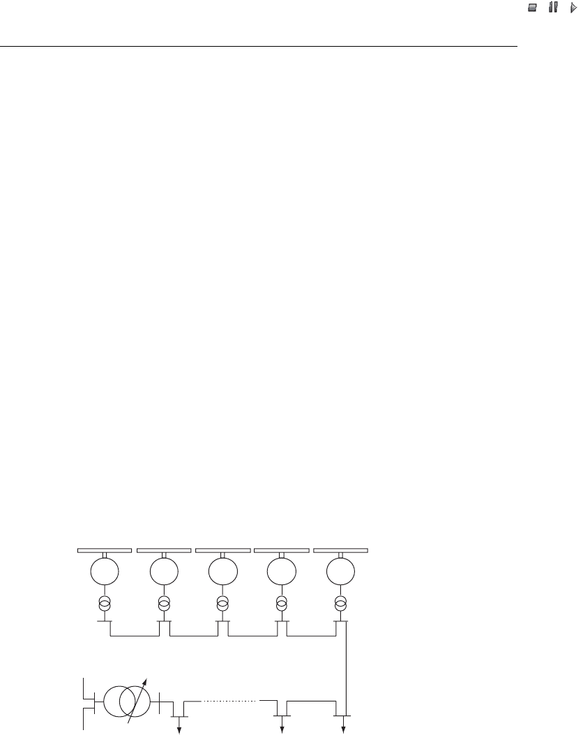
The example network with a 5 750 kW wind farm given in Figure 5.2 is used as an
illustration. The wind turbines are of a conventional design, operating at fixed speed and
using stall for power limitation at high wind speeds (wind turbine type A0). Each wind
turbine is equipped with power electronics that limits the in-rush current to the induc-
tion generator during startup and capacitors that are switched to maintain the power
Wind farm PCC:
U
n
= 22 kV
S
k
= 37.6 MVA
ψ
k
= 55°
E
Pst
= 0.7
E
Plt
= 0.5
Sum load: 2.2–7.4 MW
5 × 750 kW wind farm
132 kV 22 kV
Node
58
Node
57
Node
56
Node
55
Node
53
Node
54
1
Figure 5.2 Example network with a 5 750 kW wind farm. Note: PCC ¼point of common
coupling; U
n
¼ nominal phase-to-phase voltage; S
k
¼ short-circuit apparent power of the grid;
k
¼ network impedance phase angle; E
Pst
¼ short-term flicker emission limit; E
Ptt
¼ long-term
flicker emission limit
86 Power Quality Standards

//INTEGRAS/KCG/PAGINATION/WILEY/WPS/FINALS_14-12-04/0470855088_06_CHA05.3D – 87 – [79–96/18] 20.12.2004
7:30PM
factor close to unity during operation. Further detailed power quality characteristics of
each wind turbine, specified according to IEC 61400- 21, are given in Table 5.2, though,
for simplicity, only the data relev ant for the example network conditions are listed.
The wind farm is connected to a 22 kV distribution feeder with short-circuit apparent
power at the point of common coupling (PCC) about 10 times the installed wind power
capacity. Hence, the grid appears relatively weak and the operation of the wind farm
may be expected significantly to impact the voltage quality at customers connected to
the 22 kV feeder. The 22 kV feeder is connected via a constant rail voltage transformer
with a dead-band of 1 % to a strong 132 kV transmission line. Given the strength of
the 132 kV connection point, it is assumed that the 5 750 kW wind farm will not
significantly influence the operation at this high voltage level. Consequently, the scope
of analysis for this case study is limited to the 22 kV distribution feeder.
5.3.3 Slow voltage variations
Load-flow analyses may be carri ed out to asses s the slow voltage variations (i.e. vari-
ations in the voltage amplitude expressed as 10 min average values). In general, all
possible load cases should be included in the assessment of slow voltage variations.
For the example system, however, given its simplicity and that the wind turbines are
operated at a power facto r close to unity, it is sufficient to c onsider the two load cases
specified below that give minimum and maximum voltage amplitudes, respectively:
.
maximum consumer loads at feeder and zero wind power production;
.
minimum consumer loads at feeder and maximum continuous wind power production.
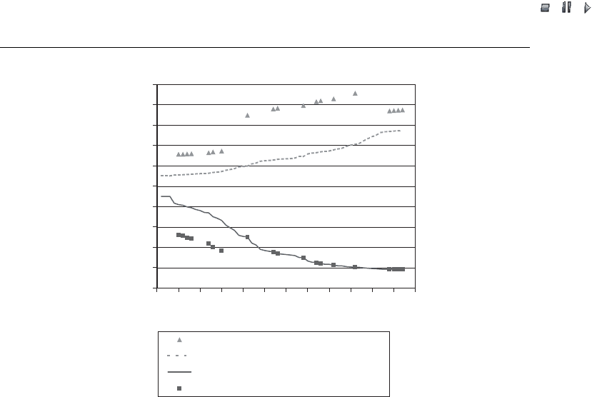
Figure 5.3 shows the results for the two load cases. Node 1 denotes the medium-
voltage (MV) node at the high-voltage (HV) transformer. The 5 750 kW wind turbi nes
are connected at nodes 54–58 (see Figure 5.2), whereas the other nodes connect con-
sumers. The voltage shown for low voltage at minimum load and maximum wind power
refers to the point immediately after the low-voltage (LV) transformer, whereas the
Table 5.2 Power quality data for example wind turbine
Quantity Value
Rated power, P
n
(kW) 750
Rated reactive power, Q
n
(kvar) 0
Nominal phase-to-phase voltage, U
n
(kV) 0.69
Maximum permitted power, P
mc
1.2 P
n
Flicker coefficient, c(
k
¼ 55
, v
a
¼ 8:2 m/s) 10.9
Maximum number of switching operations in a 10 min period, N
10
1
Maximum number of switching operation in a 2 h period, N
120
12
Flicker step factor, k
f
(
k
¼ 55
) 1.2
Voltage change factor, k
u
(
k
¼ 55
) 1.5
Note:
k
¼ network impedance phase angle; v
a
¼ annual average wind speed.
Wind Power in Power Systems 87
//INTEGRAS/KCG/PAGINATION/WILEY/WPS/FINALS_14-12-04/0470855088_06_CHA05.3D – 88 – [79–96/18] 20.12.2004
7:30PM
voltage shown for low voltage at maximum load and no wind power is at the far end of
the LV line. The difference between the per-unit (p.u.) voltages at medium and low
voltage are a result of the voltage drop at the LV lines and the assumed tap-changer
position of the LV transformers.
According to EN 50160, the slow voltage variations measured as 10 min averages at
customer inlets should lie within 10 % of U
n
during 95 % of a week. In addition, for
low voltage only, the slow voltage variations should always be within 15 % and
þ10 % of U
n
. Hence, our example system lies within these limits. However, slow voltage
variations may be a constraint on the further expansion of the wind farm as an
expansion would cause the maximum voltage to increase. However, this constraint
may easily be overcome by adjusting the power factor of the wind turbines, for instance.
A modest reduction of the power factor from unity to 0.98 (inductive) decreases the
maximum voltage by 1.5 % and makes room for more wind power. Actually, the wind
farm may expand to a total of eight 750 kW wind turbines operated at a power factor of
0.98 before slow voltage variations again become a constraint on further expansion.
Certainly, possible uncertainties in estimates of minimum and maximum load levels
may require safety margins. This does not, however, change the suggestion that a
possible slow voltage variation constraint may be counteracted by adjusting the power
factor of the wind turbines. It can be argued that a reduced power factor causes
increased network losses. This implies that a regulation of the power factor should be
used with care, and that alternative options should be assessed. Examples of alternative
options are grid reinforcement by the installation of new lines and a voltage-dependent
reduction of the wind farm power (see e.g. Tande, 2000). It is further relevant to
consider voltage-dependent power factor control that probably could substantially
0.90
0.92
0.94
0.96
0.98
1.00
1.02
1.04
1.06
1.08
1.10
0 5 10 15 20 25 30 35 40 45 50 55 60
Node
Voltage (p.u.)
Minimum load, maximum wind, low voltage
Minimum load, maximum wind, medium voltage
Maximum load, 0 wind, medium voltage
Maximum load, 0 wind, low voltage
Figure 5.3 Result of load-flow analysis
88 Power Quality Standards

//INTEGRAS/KCG/PAGINATION/WILEY/WPS/FINALS_14-12-04/0470855088_06_CHA05.3D – 89 – [79–96/18] 20.12.2004
7:30PM
reduce the increase of network losses. It is possible, with clever control and allowing
overcompensation at high load and low wind conditions, to achieve a net reduction in
grid losses. To assess this, repeated load flow analyses need to be conducted, taking
properly into account the expected distribution of consumption and wind power pro-
duction during the year [e.g. by probabilistic load flow, as in Hatziargyriou, Karakat-
sanis and Papadopoulos (1993) and in Tande and Jø rgensen (1996)].
5.3.4 Flicker
Flicker and/or rapid voltage changes are commonly due to rapid changes in the load or
to switching operations in the system. According to EN 50160, a rapid voltage change
should generally be less than 5 % of U
n
, though a change of up to 10 % of U
n
may occur
several times a day under certain circumstance s.
The flicker severity can be given as a short-term value, P
st
, measured over a period of
10 minutes, or as a long-term value, P
lt
, corresponding to a period of 2 hours, calculated
from a sequence of P
st
values:
P
lt
¼
X
12
i¼1
P
3
st;i
12
!"#
1=3
: ð5:4Þ
According to EN 50160, the long-term flicker severity has to be less than or equal to 1
during 95 % of a week. It is noted that reaction to flicker is subjective, so that in some
cases people may be annoyed by P
lt
¼ 1, for instance, whereas in other cases higher
values can be accepted.
To ensure P
lt
1 at the customer inlets, each source of flicker connected to the
network can be allowed only a limited contribution; for example, in the example
network, E
Pst
¼ 0:7 and E
Plt
¼ 0:5 at the PCC of the wind farm, where E
Pst
and E
Plt
are the short-term and long-term flicker emission limits, respectively. In other networks,
different values may be found by using IEC 61000-3-7 (IEC, 1996b) as a guide.
Wind turbines emit flicker as a result of switching operations, such as startups, and as
a result of rapid fluctuations in the output power during continuous operation.
Following the recommendations in IEC 61400-21, the flicker emission from a single
wind turbine or wind farm may be assessed. Procedures are given for assessing flicker
emission due to switching operations and due to continuous operation.
5.3.4.1 Switching operations
The procedure for assessing flicker emission due to switching operations assumes that
each wind turbine is characterised by a flicker step factor, k
f
(
k
), which is a normalised
measure of the flicker emission due to a single worst-case switching operation. The
worst-case switching ope ration is commonly a startup, although IEC 61400-21 also
requires the assessment of switching operations between gen erators (e.g. to obtain two-
speed operation), if applicable to the wind turbine in question. Further, the procedure
assumes that, for each wind turbine, information is given on the maximum number of
starts, N
10
and N
120
, that can be expected within a 10-minute and 2-hour period,
Wind Power in Power Systems 89

//INTEGRAS/KCG/PAGINATION/WILEY/WPS/FINALS_14-12-04/0470855088_06_CHA05.3D – 90 – [79–96/18] 20.12.2004
7:30PM
respectively. Based on these characteristics, the flicker emission due to worst-case
switching of wind turbines can be calculated (for a deduction of the equations, see
IEC, 2001; Tande, 2002):
P
st
¼
18
S
k
X
N
wt
i¼1
N
10
k
f;i
ð
k
ÞS
n;i
3:2
()
0:31
; ð5:5Þ
P
lt
¼
8
S
k
X
N
wt
i¼1
N
120
k
f;i
ð
k
ÞS
n;i
3:2
()
0:31
; ð5:6Þ
where N
wt
is the total number of wind turbines.
For the example specifications, P
st
¼ 0:71 and P
lt
¼ 0:68 (i.e. exceeding the assumed
example limits). Hence, the flicker emission due to startups may be a constraint on the
operation of the example wind farm. This constraint may, however, be overcome quite
easily by using another type of wind turbine with a smaller flicker step factor, k
f
[e.g. a
pitch-regulated or a (semi)variable-speed type]. Another alternative is to ensure that
only a reduced number of wind turbines are allowed to start within the same 10-minute
and 2-hour period. This involves altering the control system settings of the wind turbine
to a smaller value for N
120
and introducing a wind farm control system that allows only
a reduced number of wind turbines to start within the same 10-minute period, in effect
altering N
wt
in Equation (5.5).
5.3.4.2 Continuous operation
The procedure for assessing flicker emission due to continuous operation assumes that
each wind turbine is ch aracterised by a flicker coefficient, c(
k
, v
a
), which is a normal-
ised measure of the maximum expected flicker emission during continuous operation of
the wind turbine. To arrive at the flicker emission from a single wind turbine, the flicker
coefficient with the relevant
k
and v
a
is simply mult iplied by S
n
/S
k
, whereas the
emission from a wind farm can be found from the following equation (for a deduction
of this equation, see IEC, 2001; Tande, 2002):
P
st
¼ P
lt
¼
1
S
k
X
N
wt
i¼1
c
i
ð
k
; v
a
ÞS
n;i
2
()
0:5
: ð5:7Þ
P
st
¼ P
lt
in Equation (5.7) because it is probable that conditions during the short-term
period persist over the long-term period. Further, Equation (5.7) assumes that the
maximum power levels between wind turbines are uncorrelated. At special conditions,
however, wind turbines in a wind farm may ‘synchronise’, causing power fluctuations to
coincide. Equation (5.7) would then underestimate the flicker emission. This was assessed
in (Tande, Relakis and Alejandro, 2000), and it was concluded that, for common
conditions, Equation (5.7) will provide a good estimate (see also Figure 5.4).
For the example specifications, P
st
¼ P
lt
¼ 0:49, which lies just within the assumed
example limit of E
Plt
¼ 0:5. If the wind farm was expanded with more wind turbines of
90 Power Quality Standards