AckermannTh. (ed) Wind Power in Power Systems
Подождите немного. Документ загружается.


//INTEGRAS/KCG/PAGINATION/WILEY/WPS/FINALS_14-12-04/0470855088_07_CHA06.3D – 101 – [97–114/18]
20.12.2004 7:35PM
Reactive power and power factor
The reactive power is measured as a 10-minute average value (IEC guideline) or as a
1-minute average value (German guideline) over the whole power range of the wind
turbine. The reactive power is given for each 10 % step of the active power from 0 % to
100 % of rated power. Instead of reactive power, the German guideline requires the
measurement of the power factor.
Harmonics
According to the guidelines, harmonic measurements are not required for fixed-speed
wind turbines (Type A), where the induction generator is directly connected to the
grid.
(1)
Harmonic measurements are required only for variable-speed turbines with
electronic power converters (Types C and D).
Wind turbines with electronic power converters produce harmonic currents. The three
guidelines include different requirements concerning harmonic measurements. The IEC
guideline only requires the measurement of integer harmonic currents up to the 50th
order. In general, the power converters of wind turbines are pulse-width modulated
(PWM) invert ers, though, which have clock frequencies in the range of 2–3 kHz and
produce mainly interharmonic currents. Thus the requirements of the IEC guideline do
not really reflect the harmonic emission of the wind turbine.
The MEASNET guideline and also the Germ an guideline require measurements of
interharmonic currents of up to 2 kHz and of current distortions in the higher frequency
range of between 2–9 kHz. That means that these two guidelines reflect the harmonic
emission of wind turbines. Even though both guidelines require measur ements in the
same frequency range, the results of such measurements are not comparable. The
MEASNET guideline requires measuring intervals of 10 minutes. The relevant value
is the maximum 10-minute value of each frequency. Integer harmonic currents and
interharmonic currents are grouped according to IEC 61000-4-7 Ed.2.0 (IEC, 2002). In
this context, grouping means that all interharmonic currents between two neighbouring
integer harmonics are combined into a single interharmonic current, for example. Current
distortions in the higher frequency range are grouped into bandwidths of 200 Hz.
The German guidel ine requires measuring intervals of 8 line periods. For each
frequency, a 99 % value of the harmoni c (or interharmonic) current is determined (i.e.
the value that is not exceeded in 99 % of all cases). These 99 % values are relevant.
Grouping for interharmonics or integer harmonics is not used. Thus, interharmonics are
given in steps of 6.25 Hz. Similar to the MEASNET guideline, the current distortions in
the higher frequency range are grouped into bandwidths of 200 Hz.
In practice, the main difference between the German and the MEASNET guideline lies
in the different averaging intervals. In general, the harmonic emission of wind turbines
with power converters is not steady. The harmonics, interharmonics and higher frequency
distortions behave stochastically. There is an averaging effect, which leads to lower values
in the measurements according to the MEASNET guideline. Owing to the very short
measurement intervals of the German guideline, the corresponding values are higher.
(1)
For definitions of turbine Types A to D see Section 4.2.3.
Wind Power in Power Systems 101
//INTEGRAS/KCG/PAGINATION/WILEY/WPS/FINALS_14-12-04/0470855088_07_CHA06.3D – 102 – [97–114/18]
20.12.2004 7:35PM
One of the main problems of the harmonic measurements at wind turbines is the
influence of the already existing harmonic voltages in the grid. The voltage waveshape of
the grid is, of course, not sinusoidal. There are always already harmonic voltages in the
grid, such as integer harmonics of 5th and 7th order, which affect the measurements. In
many cases, the wind turbine behaves like a consumer of such harmonics. It makes no
sense to evaluate such harmonics, because they originate from the grid. The problem is
to identify and separate the harmonic emission originating from the turbine and that
originating from the grid. A first indicator may be the phase angle of the harmonic and
the time or power dependency. We also have to know whether there are wind turbines
with power converters in the vicinity of the turbine that is measured. The harmonic
emission of the neighbouring turbines can influence the harmonic measurement, par-
ticularly as the harmonic emission of the neighbouring turbines may also be correlated
to the wind speed.
Flicker
The term ‘flicker’ means the flickering of light caused by fluctuations of the mains
voltage, which can cause distortions or inconvenience to people as well as other elec-
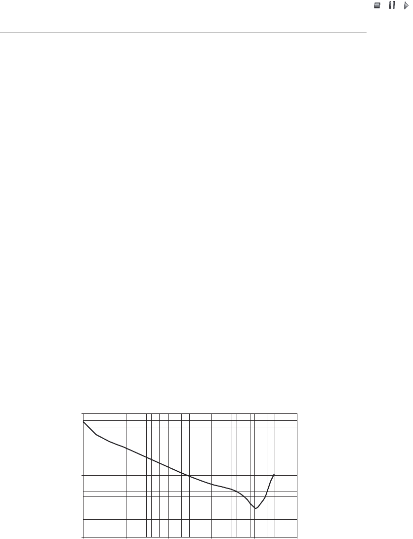
trical consumers. Flicker is defined as the fluctuation of voltage in a frequency range of
up to 35 Hz. Flicker evaluation is based on IEC 61000-3-7 (IEC, 1996). The basis for the
evaluation is the curve given in Figure 6.1, with a threshold value for the short-term
flicker disturbance factor, P
st
,ofP
st
¼ 1. This curve shows the level where flicker is a
visible disturbing factor to people. The most sensitive frequency is 8.8 Hz.
IEC 61000-4-15 (IEC, 2003) specifies a flickermeter that can be used to measure
flicker directly. In general, flicker is the result of the flicker that is already present in
the grid and of the emissions to be measured. A direct measurement will require an
undisturbed constant-impedance power supply. However, this is not feasible for wind
turbines because of their size. The flicker measurement is therefore based on measure-
ments of three instantaneous phase voltages and currents, which are followed by an
analytical determination of P
st
for different grid impedance angles. The measured
0.1
1
10
0.1 1 10 100 1000 10 000
Rectangular voltage changes per minute
Voltage change, d (%)
Figure 6.1 Curve of the regular rectangular voltage charge (as a percentage of the nominal value)
against the number of changes per minute, for a short-term flicker disturbance, P
st
,of1
102 Power Quality Measurements
//INTEGRAS/KCG/PAGINATION/WILEY/WPS/FINALS_14-12-04/0470855088_07_CHA06.3D – 103 – [97–114/18]
20.12.2004 7:35PM
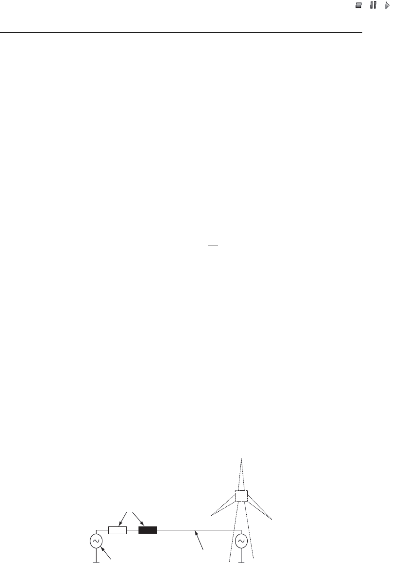
voltage and current time series of the wind turbines are the input to a simple grid model
(see Figure 6.2). For different grid impedances, especially grid impedance angles, time
series of voltage fluctuations are calculated for this fictitious grid. The simulated time
series of instantaneous voltage fluctuations are the input to the standard voltage flicker
algorithm in order to generate the flicker emission values P
st
. The algorithm is descri bed
in IEC 61000-4-15. Such P
st
values are calculated for a larger number of measured time
series over the whole power range of the turbine. Weighted with standard wind-speed
distributions, a 99 percentile of the P
st
values is calculated, which ensures that for 99 %
of the time, the flicker of the wind turbine will be within this 99 percentile. Last, a flicker
coefficient is calculated from this 99 percentile of the P
st
values. The flicker coefficient
gives a normalised, dimensionless measure of the flicker, independent of the network
situation and thus independent of the selected short-circuit apparent power of the
fictitious grid. It determines the ratio between short-circuit power and generator-rated
apparent power, which is necessary to achieve a long-term flicker level, P
lt
, of 1. The
flicker coefficient c is defined as:
cð
k
; V
a
Þ¼P
lt
S
k
S
n
ð6:1Þ
where
c(
k
, V
a
) is the flicker coefficient, dependent on the grid impedance angle
k
and on
the annual average wind speed V
a
.
S
k
is the short-circuit power of the grid at the point of common coupling (PCC).
S
n
is the apparent power of the wind turbine at rated power .
P
lt
is the long-term flicker emission.
This flicker coefficient can be used by utilities to calculate the flicker emission of a wind
turbine or a wind farm at a specific site.
The procedures of IEC 61400-21 (IEC, 2001) and the German guideline are similar.
The only difference is that the German guideline requires 1-minute time inter vals and
thus 1-minute P
st
values, and the IEC guideline requires 10-minute intervals. This leads
to different results, with the flicker coefficients of the German guideline in general
slightly exceeding those of the IEC guideline.
Wind
turbine
Grid impedances
Ideal voltage supply
Figure 6.2 Simulation model for flicker measurements
Wind Power in Power Systems 103

//INTEGRAS/KCG/PAGINATION/WILEY/WPS/FINALS_14-12-04/0470855088_07_CHA06.3D – 104 – [97–114/18]
20.12.2004 7:35PM
Switching operations
Switching operations can cause voltage fluctuations due to in-rush currents and can
cause flicker. Therefore, the German guideline and the IEC guideline as well as the
MEASNET guideline require measurements concerning flicker and voltage fluctuations
during switching operations. Owing to the already existing flicker and voltage fluctu-
ations in the grid, the measur ement procedure is similar to the procedure for flicker
measurements during normal operation. This means that the measured time series
during switching operations is inserted into a grid model with specific grid impedances
(see Figure 6.2). The model produces the time series of voltages, from which the voltage
fluctuations are calculated. The normalised voltage fluctuations lead to a voltage change
factor, which is a dimensionless value of the voltage fluctuations during switching
operations. In addition, the standard flicker algorithm is used to calculate a flicker step
factor from the voltage fluctuations that the grid model generates. This flicker step
factor is the basis for the calculation of the flicker impression that the switching
operations of a wind turbine or farm at a specific site will cause.
The German guideline requires calculation methods that are similar to those of the
IEC guideline. In the German guideline, though, the flicker impression and the voltage
fluctuation are combined into a single grid-related switching factor. This factor is very
easy for the utilities to apply. It is, however, less accurate than the procedure of the IEC
and MEASNET guidelines.
The following switching operations have to be measured:
.
cut-in at cut-in wind speed;
.
cut-in at rated wind speed;
.
switching operations between generator stages;
.
service cut-out at rated power (German guideline only).
6.2.3 Future aspects
In some countries, such as Germany and Denmark, there is a high penetration of
electricity generated from wind energy. Grid operators will have to take precautions
in order to ensure a safe and stable operation of the grid, taking into account the
expected increase in production from wind energy. Therefore, some utilities have
established new additional requirements (EON, 2003; VDN, 2004; Eltra, 2000; NGC,
2004 for a discussion of the new grid requirement s, see Chapter 7).
Until now, the philosophy regarding wind farms connected to the grid has been to
switch off the farm as soon as there is a fault on the grid. The new guidelines are a
radical change to this philosophy. They require wind farms to remain connected in the
case of grid faults (e.g. short- term voltage drops). The wind farms are expected to
support the grid. Therefore, wind farms have to control reactive power over a wide
range, deliver reactive power in the case of voltage drops and remain connected during
short-term voltage drops. And they must be able to operate over a wide frequency range.
In order to ensure that wind turbines and wind farms will fulf il these new require-
ments, in Germany, an additio nal measurement guideline has been developed (FGW,
2003). This guideline includes methods to check the compatibility of the turbine or farm
104 Power Quality Measurements

//INTEGRAS/KCG/PAGINATION/WILEY/WPS/FINALS_14-12-04/0470855088_07_CHA06.3D – 105 – [97–114/18]
20.12.2004 7:35PM
with the requirements of EON (2003) and VDN (2004). The guideline includes the
following measurements and checks:
.
range of reactive power (capacitive as well as inductive);
.
power gradient after grid losses;
.
operation at underfrequency and overfrequency;
.
power reduction through set-point signal;
.
protection system concerning frequency and voltage changes;
.
behaviour of the wind turbine in the case of short voltage drops (ride-through capability).
6.3 Power Quality Characteristics of Wind Turbines and Wind Farms
The grid interferences of wind turbines or wind farms have different causes, which are
mostly turbine-specific. The relevant parameters are listed in Table 6.2. Average power
production, turbulence intensity and wind shear refer to causes that are determined by
meteorological and geographical conditions. All the other causes are attributable to the
technical performance of the wind turbine. This performance is determined not only by
the characteristics of the electrical components, such as generators, transformers and so
on, but also by the aerodynamic and mechanical behaviour of rotor and drive train. The
turbine type (i.e. variable versus fixed speed stall versus pitched controlled) is of major
importance to the power quality characteristics of wind turbines and wind farms.
6.3.1 Power peaks
Variable-speed wind turbines (Types C and D) can control the power output of the
inverter system by pitch c ontrol, thus smoothing power fluctuatio ns as well as power
peaks. Thus the power peaks lie within the range of the rated power. Instantaneous
power peaks of fixed-speed wind turbines (Type A) often exceed rated power by 30 % or
more, even in the case of pitch-controlled fixed-speed turbines. The pitch control is not
Table 6.2 Grid interferences caused by wind turbines and wind farms
Parameter Cause
Voltage rise Power production
Voltage fluctuations and flicker Switching operations
Tower shadow effect
Blade pitching error
Yaw error
Wind shear
Fluctuations of wind speed
Harmonics Frequency inverter
Thyristor controller
Reactive power consumption Inductive components or generating systems
(asynchronous generator)
Voltage peaks and drops Switching operations
Wind Power in Power Systems 105

//INTEGRAS/KCG/PAGINATION/WILEY/WPS/FINALS_14-12-04/0470855088_07_CHA06.3D – 106 – [97–114/18]
20.12.2004 7:35PM
fast enough to control fast power peaks. Slower power peaks, such as 1-minute and 10-
minute power peaks, can be reduced by the pitch control. These slower power peaks are
therefore also close to rated power, also for pitch-controlled fixed-speed turbines (Type
A1). The power peaks of a stall-controlled fixed-speed turbine (Type A0) depend on air
pressure and air temperature, among other things. This has the effect that 1-minute and
10-minute power peaks often exceed rated power by about 10 % to 20 %.
The number of wind turbines on a wind farm is important for smoothing power
peaks. In particular, fast power peaks at the individual wind turbines of a wind farm are
in general uncorrelated and thus smoothed throughout the wind farm. IEC 61400-21
includes a formula for this smoothing effect, which in principal adds up the power peaks
of the single wind turbines geometrically.
6.3.2 Reactive power
The reactive power demand of the asynchronous g enerator of fixed-speed wind turbines
(Type A) is partly compensat ed by capacitor banks. Thus the power factor (i.e. the ratio
of active power and apparent power) lies, in general, at about 0.96. Variable-speed wind
turbines with PWM inverter systems (Types C and D) have an inverter to control the
reactive power. Thus, these wind turbi nes have, in general, a power factor of 1.00. These
turbines can control the reactive power over a wide range (inductive and capacitive). It is
therefore possible to control the voltage and to keep it more stable at the grid connec-
tion point of the wind farm or wind turbine (see also Chapter 19).
6.3.3 Harmonics
Today’s variable-speed turbines (Types C and D) are equipped with self-commutated
inverter systems, which are mainly PWM inverters, using an insulated gate bipolar
transistor (IGBT; see also Chapter 4). This type of inverter has the advantage that both
the active power and the reactive power can be controlled. It has the disadvantage,
though, that it produces harmonic currents. In general, the inverter generates harmonics
in the range of some kilohertz. Therefore, filters are necessary to reduce the harmonics.
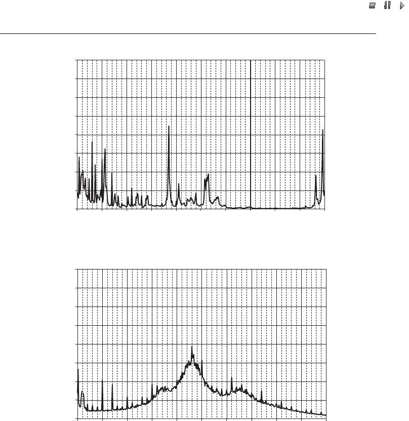
Two types of PWM inverters are used: those with a fixed clock frequency and those
with a variable clock frequency. Figure 6.3 gives examples of the harmonic emission of
wind turbines with such inverter systems. The main difference between each type is that
the inverter with a fixed clock frequency [Figure 6.3(a)] produces single interharmonics
in the range of the clock frequency and multiples of the clock frequency. Inverters with
variable clock frequency [Figure 6.3(b)] have a wide band of interharmonics and integer
harmonics. Resonances of the grid are excited by this wide band of interharmoni cs and
integer harmonics. The result are interharmonic and harmonic cu rrents, as Figure 6.3(b)
illustrates, where the specific maximum occurs at the resonance frequency of the grid.
The measurement of the harmonic currents poses one of the biggest challenges to the
measurement of power quality. Harmonic current measurements require great accuracy,
even for high frequencies, because the measurements refer to interharmonics that are in the
range of 0.1 % of the rated current for frequencies of up to 9 kHz (for MEASNET and the
German guideline). Therefore, up to 9 kHz, current clamps need to have a linear ratio.
106 Power Quality Measurements
//INTEGRAS/KCG/PAGINATION/WILEY/WPS/FINALS_14-12-04/0470855088_07_CHA06.3D – 107 – [97–114/18]
20.12.2004 7:35PM
Harmonic measurements at the low-voltage side of the wind turbine may give results
that are different from measurements at the medium-voltage side. Investigations have
shown that in some cases the transformer of the turbine has an influence on the
harmonics (Santjer, 2003). The transformers of wind turbines are often connected at
the medium-voltage side in delta operation and at the low-voltage side in star operation.
Owing to this connection, a single phase at the medium-voltage side is influenced by two
phases at the low-voltage side. This can lead to a smoothing effect that reduces some of
the harmonics. In particu lar, the so-called ‘zero current’ may be eliminated. Thus
harmonic measurements at the medium-voltage side of the transformer often produce
0
0.05
0.1
0.15
0.2
0.25
0.3
0.35
0.4
0 250 500 750 1000 1250 1500 1750 2000 2250
Frequency (Hz)
2500
Current /rated current (%)
(
a
)
0
0.05
0.1
0.15
0.2
0.25
0.3
0.35
0.4
0 250 500 750 1000 1250 1500 1750 2000 2250 2500
Frequency (Hz)
Current/rated current (%)
(b)
Figure 6.3 Harmonic current emission of a variable-speed wind turbine where the inverter has
(a) a fixed clock frequency and (b) a variable clock frequency
Wind Power in Power Systems 107
//INTEGRAS/KCG/PAGINATION/WILEY/WPS/FINALS_14-12-04/0470855088_07_CHA06.3D – 108 – [97–114/18]
20.12.2004 7:35PM
lower values than at the low-voltage side, but, for practical reasons, measurements at the
medium-voltage side are often more difficult than at the low-voltage side.
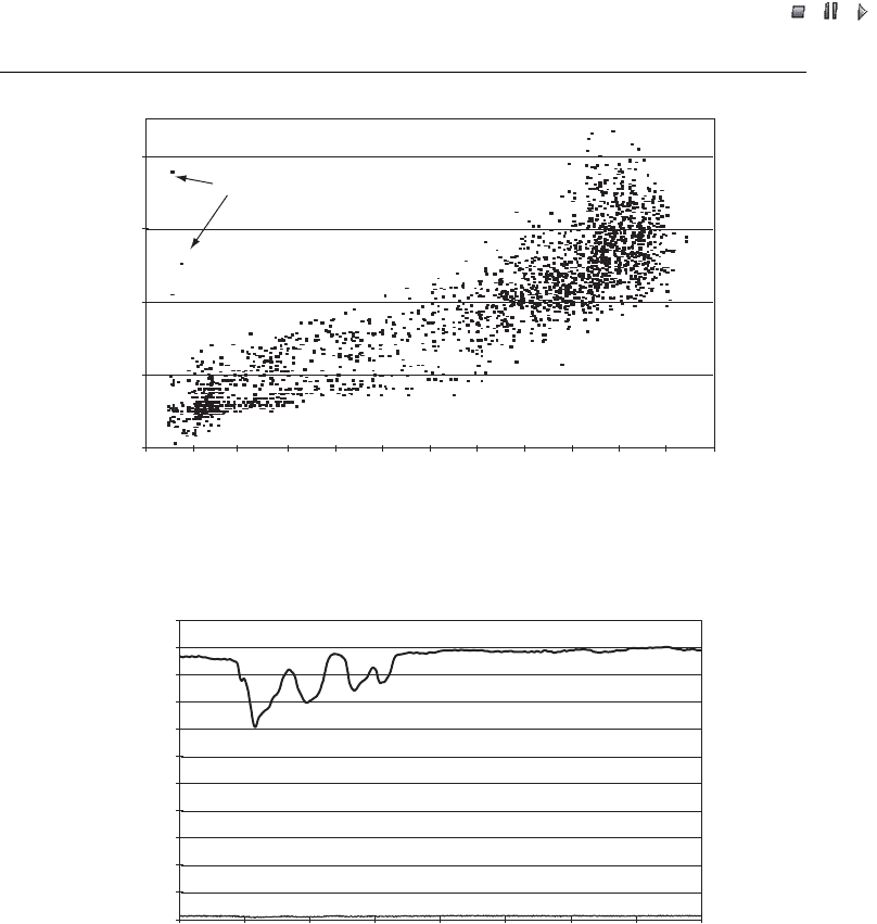
6.3.4 Flicker
Fluctuations of active and/or reactive power of wind turbi nes cause flicker. Active
power fluctuations of wind turbines may be caused by the effect of the wake of the
tower, by yaw errors, by wind shear, by wind turbulences or by fluctuations in the
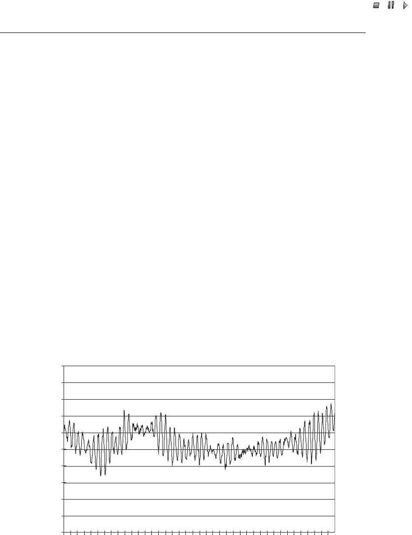
control system. The main reason for flicker in fixed-speed turbines (Type A) is the wake
of the tower. Each time a rotor blade passes the tower, the power output of the turbine is
reduced. This effect causes periodical power fluctuations with a frequency of about
1 Hz. Figure 6.4 gives an example of such power fluctuations in a fixed-speed wind
turbine. Power fluctuations due to wind-speed fluctuations hav e lower frequencies and
thus are less critical for flicker. In general, the flicker of fixed-speed turbines reaches its
maximum at high wind speeds. Owing to smoot hing effects, large wind turbines gen-
erally produce lower flicker than small wind turbines, in relation to their size. An
example of the flicker behaviour of a fixed-speed turbine (Type A) is given in Figure 6.5.
For variable-speed turbines (Types C and D), fast power fluctuations are smoothed
and the wake of the tower does not affect power output. Therefore, the flicker of
variable-speed turbines (Types C and D) is in general lower than the flicker of fixed-
speed turbines (Type A). Figure 6.6 gives an example of the power output of a variable-
speed wind turbine.
In wind farms, power fluctuations are smoothed because of the fact that the power
fluctuations of the single wind turbines are uncorrelated. The flicker of a wind farm is
0
0.05
0.1
0.15
0.2
0.25
0.3
0.35
0.4
0.45
0.5
0 5 10 15 20 25 30 35
Time (s)
Active power/rated power
Figure 6.4 Active power output of a fixed-speed wind turbine (Type A); periodical fluctuations
are due to the wake of the tower
108 Power Quality Measurements
//INTEGRAS/KCG/PAGINATION/WILEY/WPS/FINALS_14-12-04/0470855088_07_CHA06.3D – 109 – [97–114/18]
20.12.2004 7:35PM
the geometrical sum of the flicker of all single turbines in the farm. This means that for a
wind farm consisting of n single turbines of the same type, the flicker of the farm is
ffiffiffi
n
p
times the flicker of a single wind turbine.
6.3.5 Switching operations
Voltage changes during switching operations are due to in-rush current s and the
respective changes in the active and reactive power of a wind turbine. For fixed-speed
turbines, a soft-starter limits the in-rush current of the asynchronous generat or. The
0
0.1
0.2
0.3
0.4
0 0.1 0.2 0.3 0.4 0.5 0.6 0.7 0.8 0.9 1 1.1 1.2
Active power/rated power
Flicker, P
st
Switchings
Figure 6.5 Flicker behaviour of a fixed-speed wind turbine as a function of active power output
0
0.1
0.2
0.3
0.4
0.5
0.6
0.7
0.8
0.9
1
1.1
90 95 100 105 110 115 120 125 130
Time (s)
Active power/rated power
Reactive power/rated power (kvar/kW)
Active power
Reactive power
Figure 6.6 Power output of a variable-speed wind turbine
Wind Power in Power Systems 109
//INTEGRAS/KCG/PAGINATION/WILEY/WPS/FINALS_14-12-04/0470855088_07_CHA06.3D – 110 – [97–114/18]
20.12.2004 7:35PM
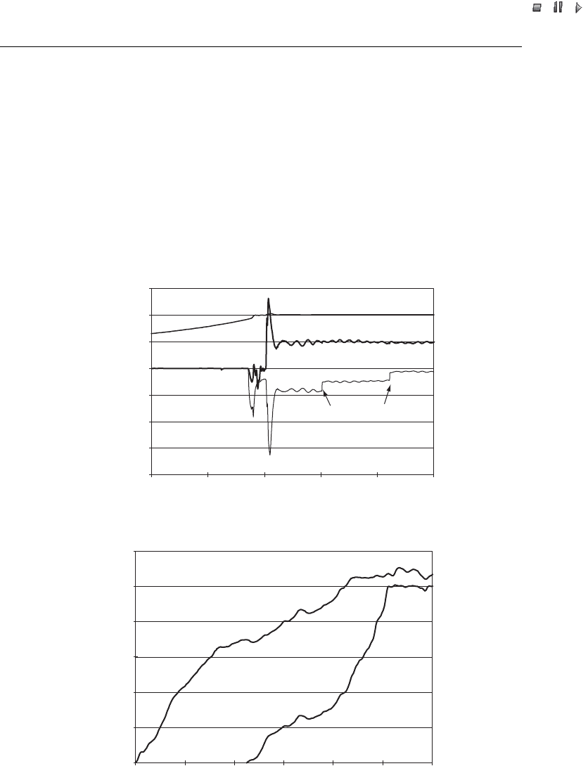
soft-starter is generally based on thyristor technology and limits the highest root mean
square (RMS) value of the in-rush current to a level below twice the rated current of the
generator. Figure 6.7(a) gives an example of the cut-in of a fixed-speed turbine (Type A).
Before cut-in, the rotational speed of the rotor and that of the asynchronous generator
increase, driven by the wind. Once the synchronous speed is reached, the generator will
be connected to the grid. The soft-starter is in operation for about 1 or 2 seconds and
limits in-rush current. During this period, the generator needs reactive power to become
magnetised. A few seconds after the generator is connected, the capacitors are switched
on to minimis e the demand of reactive power. The fast power changes during the
switching operation cause flicker. The (large) changes in active and reactive power cause
voltage fluctuations.
–2
–1.5
–1
–0.5
0
0.5
1
1.5
0 5 10 15 20 25
Time (s)
Active power/rated power,
Reactive power/rated power (kvar/kw)
Rotational speed/synchronous speed
Cut-in of capacitors
Active power
Rotational speed
Reactive power
(a)
0
0.2
0.4
0.6
0.8
1
1.2
Time (s)
Active power/rated power
Rotational speed/synchronous speed
Rotational speed
Active power
0 102030405060
(b)
Figure 6.7 Cut-in of (a) a fixed-speed wind turbine (Type A) and (b) a variable-speed wind
turbine (Types C and D)
110 Power Quality Measurements