AckermannTh. (ed) Wind Power in Power Systems
Подождите немного. Документ загружается.


//INTEGRAS/KCG/PAGINATION/WILEY/WPS/FINALS_14-12-04/0470855088_04_CHA03.3D – 51 – [25–52/28] 20.12.2004
7:28PM
[4] Kaijser, A. (1995) ‘Controlling the Grid: The Development of High-tension Power Lines in the Nordic
Countries’, in Nordic Energy Systems – Historical Perspectives and Current Issues. Science History
Publication, Catson, MA, USA, pp. 31–54.
[5] Hills, R. L. (1994) Power from Wind – A History of Windmill Technology, Cambridge University Press,
Cambridge.
[6] Hughes, T. P. (1993) Networks of Power, The John Hopkins University Press, Baltimore, MD.
[7] Hunt, S., Shuttleworth, G. (1996) Competition and Choice in Electricity, John Wiley & Sons, Ltd/Inc.,
Chichester.
[8] Petersen, E. L., Mortensen, N. G., Landberg, L., Højstrup, J., Frank, H. P. (1998) ‘Wind power
Meteorology, Part II: Siting and Models’, Wind Energy; 1(2) 55–72.
[9] Rosas, P. (2003) Dynamic Influences of Wind Power on the Power System, PhD thesis, Ørsted Institute and
Technical University of Denmark, March 2003.
[10] So
¨
der, L. (1997) ‘Vindkraftens effektva
¨
rde’ (Capacity Credit of Wind Power; in Swedish); Elforsk
Rapport 97:27, Stockholm, Sweden, December 1997.
[11] So
¨
der, L. (1999) ‘Wind Energy Impact on the Energy Reliability of a Hydro-thermal Power System in a
Deregulated Market’, paper presented at the 13th Power Systems Computation Conference, 28 June to
2 July 1999, Trondheim, Norway.
[12] So
¨
der, L. (2002) ‘Explaining Power System Operation to Nonengineers’, Power Engineering Review, IEEE
22(4) 25–27.
Wind Power in Power Systems 51

//INTEGRAS/KCG/PAGINATION/WILEY/WPS/FINALS_14-12-04/0470855088_04_CHA03.3D – 52 – [25–52/28] 20.12.2004
7:28PM

//INTEGRAS/KCG/PAGINATION/WILEY/WPS/FINALS_14-12-04/0470855088_05_CHA04.3D – 53 – [53–78/26] 20.12.2004
7:29PM
4
Generators and Power
Electronics for Wind Turbines
Anca D. Hansen
4.1 Introduction
Today, the wind turbines on the market mix and match a variety of innovative concepts
with proven technologies both for generators and for power electronics. This chapter
presents from an electrical point of view the current status of generators and power
electronics in wind turbine concepts. It describes classical and new concepts of gen-
erators and power electronics based on technical aspects and market trends.
4.2 State-of-the-art Technologies
This section will describe the current status regarding generators and power electronics
for wind turbines. In order to provide a complete picture, we will first briefly describe
the common power control topologies of wind turbines.
4.2.1 Overview of wind turbine topologies
Wind turbines can operate either with a fixed speed or a variable speed.
4.2.1.1 Fixed-speed wind turbines
In the early 1990s the standard installed win d turbines operated at fixed speed. That
means that regardless of the wind speed, the wind turbine’s rotor speed is fixed and
determined by the frequency of the supply grid, the gear ratio and the generator design.
Wind Power in Power Systems Edited by T. Ackermann
Ó 2005 John Wiley & Sons, Ltd ISBN: 0-470-85508-8 (HB)

//INTEGRAS/KCG/PAGINATION/WILEY/WPS/FINALS_14-12-04/0470855088_05_CHA04.3D – 54 – [53–78/26] 20.12.2004
7:29PM
It is characteristic of fixed-speed wind turbines that they are equipped with an
induction generator (squirrel cage or wound rotor) that is directly connected to the
grid, with a soft-starter and a capacitor bank for reducing reactive power compensation.
They are designed to achieve maximum efficiency at one particular wind speed. In order
to increase power production, the generator of some fixed-speed wind turbines has two
winding sets: one is used at low wind speeds (typically 8 poles) and the other at medium
and high wind speeds (typically 4–6 poles).
The fixed-speed wind turbine has the advantage of being simple, robust and reliable
and well-proven. And the cost of its electrical parts is low. Its disadvantages are an
uncontrollable reactive power consumption, mechanical stress and limited power qual-
ity control. Owing to its fixed-speed operation, all fluctuations in the wind speed are
further transmitted as fluctuations in the mechanical torque and then as fluctuations in
the electrical power on the grid. In the case of weak grids, the power fluctuations can
also lead to large voltage fluctuations, which, in turn, will result in significant line losses
(Larsson, 2000).
4.2.1.2 Variable-speed wind turbines
During the past few years the v ariable-speed wind turbine has become the dominant
type among the installed wind turbines.
Variable-speed wind turbines are designed to achieve maximum aerodynamic
efficiency over a wide range of wind speeds. With a variable-speed operation it has
become possible continuously to adapt (accelerate or decelerate) the rotational speed
! of the wind turbine to the wind speed v. This way, the tip speed ratio is kept
constant at a predefined value that corresponds to the maximum power coefficient.
(1)
Contrary to a fixed-speed system, a variable-speed system keeps the generator torque
fairly constant and the varia tions in wind are absorbed by changes in the generator
speed.
The electrical system of a variable-speed wind turbine is more complicated than that
of a fixed-speed wind turbine. It is typically equipped with an induction or synchronous
generator and connected to the grid through a power converter. The power converter
controls the generator speed; that is, the power fluctuations caused by wind variations
are absorbed mainly by changes in the rotor generator sp eed and consequently in the
wind turbine rotor speed.
The advantages of variable-speed wind turbines are an increased energy capture,
improved power quality and reduced mechanical stress on the wind turbine. The
disadvantages are losses in power electronics, the use of more components and the
increased cost of equipment because of the power electronics.
The introduction of variable-speed wind-turbine types increases the number of applic-
able generator types and also introduces several degrees of freedom in the combination
of generator type and power converter type.
(1)
Tip speed ratio, , is equal to !R/v, where R is the radius of the rotor.
54 Generators and Power Electronics

//INTEGRAS/KCG/PAGINATION/WILEY/WPS/FINALS_14-12-04/0470855088_05_CHA04.3D – 55 – [53–78/26] 20.12.2004
7:29PM
4.2.2 Overview of power control concepts
All wind turbines are designed with some sort of power control. There are different ways
to control aerodynamic forces on the turbine rotor and thus to limit the power in very
high winds in order to avoid damage to the wind turbine.
The simplest, most robust and cheapest control method is the stall control (passive
control), where the blades are bolted onto the hub at a fixed angle. The design of rotor
aerodynamics causes the rotor to stall (lose power) when the wind speed exceeds a
certain level. Thus, the aerodynamic power on the blades is limited. Such slow aero-
dynamic power regulation causes less power fluctuations than a fast-pitch power regu-
lation. Some drawbacks of the method are lower efficiency at low wind speeds, no
assisted startup and variations in the maximum steady-state power due to variations in
air density and grid frequencies (for an example, see also Chapter 15).
Another type of control is pitch control (active control), where the blades can be
turned out or into the wind as the power output becomes too high or too low,
respectively. Generally, the advantages of this type of control are good power control,
assisted startup and emergency stop. From an electrical point of view, good power
control means that at high wind speeds the mean value of the power output is kept close
to the rated power of the generator. Some disadvantages are the extra complexity arising
from the pitch mechanism and the higher power fluctuations at high wind speeds. The
instantaneous power will, because of gusts and the limited speed of the pitch mechan-
ism, fluctuate around the rated mean value of the power.
The third possible co ntrol strategy is the active stall control. As the name indicates, the
stall of the blade is actively controlled by pitching the blades. At low wind speeds the
blades are pitched similar to a pitch-controlled wind turbine, in order to achieve
maximum efficiency. At high wind speeds the blades go into a deeper stall by being
pitched slightly into the direction opposite to that of a pitch-controlled turbine. The
active stall wind turbine achieves a smoother limited power, without high power
fluctuations as in the case of pitch-controlled wind turbines. This control type has the
advantage of being able to compensate variations in air den sity. The combination with
the pitch mechanism makes it easier to carry out emergency stops and to start up the
wind turbine.
4.2.3 State-of-the-art generators
In the following, the most commonly applied wind turbine configurations are classified
both by their ability to control speed and by the type of power control they use.
Applying speed control as the criterion, there are four different dominating types of
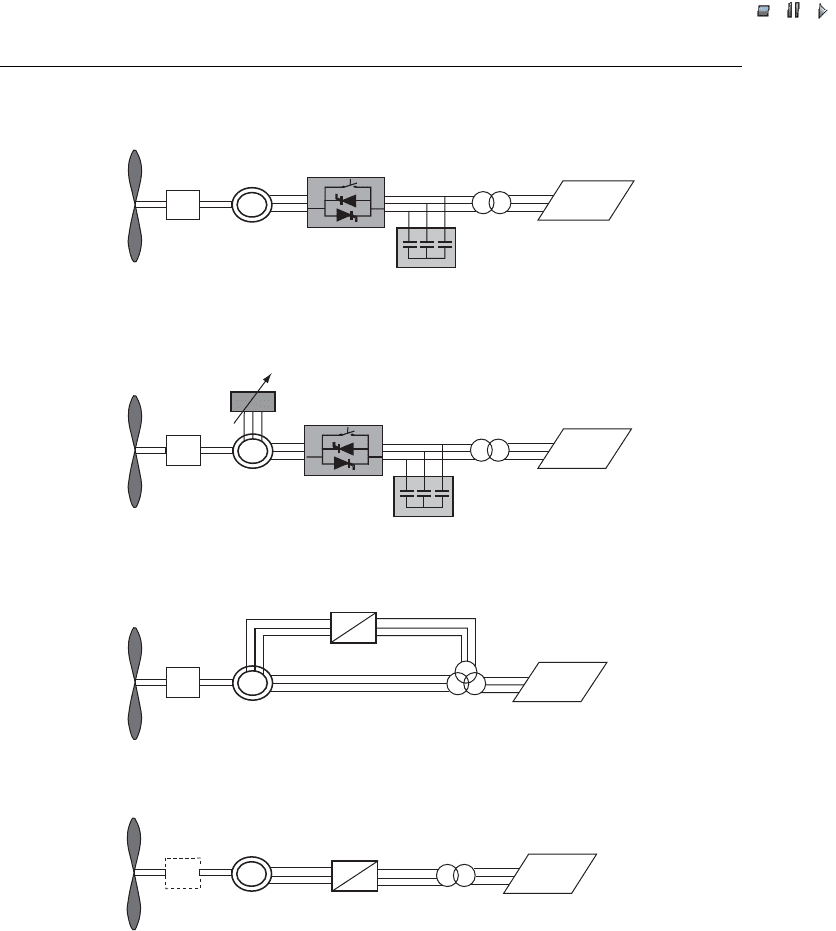
wind turbines, as illustrated in Figure 4.1.
Wind turbine configurations can be further classified with respect to the type of power
(blade) control: stall, pitch, active stall. Table 4.1 indicates the different types of wind
turbine configurations, taking both criteria (speed control and power control) into
account. Each combination of these two criteria receives a label; for example, Type
A0 denotes the fixed-speed stall-controlled wind turbine. The grey zones in Table 4.1
indicate the combinations that a re not used in the wind turbine industry today (e.g.
Type B0).
Wind Power in Power Systems 55
//INTEGRAS/KCG/PAGINATION/WILEY/WPS/FINALS_14-12-04/0470855088_05_CHA04.3D – 56 – [53–78/26] 20.12.2004
7:29PM
In this chapter, we will look mainly at the standard wind turbine types, depicted
in Figure 4.1 and Table 4.1. Other alternative, slightly different, wind turbine
designs will not be discus sed. Therefore, only the typical wind turbine configurations
and their advantages as well as disadvantages will be presented in the following
discussion.
SCIG
Gear
Type A
Gear
Grid
Soft-starter
Capacitor bank
Gear
Type B
Gear
GearGear
Gear
Grid
WRIG
Soft-starter
Capacitor bank
Variable resistance
Type D
~
~
Grid
Gear
PMSG/WRSG/WRIG
Full-scale
frequency converter
Type C
Grid
WRIG
Partial scale
frequency converter
~
~
Figure 4.1 Typical wind turbine configurations. Note: SCIG ¼squirrel cage induction generator;
WRIG ¼wound rotor induction generator; PMSG ¼permanent magnet synchronous generator;
WRSG ¼wound rotor synchronous generator. The broken line around the gearbox in the Type D
configuration indicates that there may or may not be a gearbox
56 Generators and Power Electronics

//INTEGRAS/KCG/PAGINATION/WILEY/WPS/FINALS_14-12-04/0470855088_05_CHA04.3D – 57 – [53–78/26] 20.12.2004
7:29PM
4.2.3.1 Type A: fixed speed
This configuration denotes the fixed-speed wind turbin e with an asynchronous squirrel
cage induction generator (SCIG) directly connected to the grid via a transformer (see
Figure 4.1). Since the SCIG always draws reactive power from the grid, this configur-
ation uses a capacitor bank for reactive power compensation. A smoother grid connec-
tion is achieved by using a soft-starter.
Regardless of the power control principle in a fixed-speed wind turbine, the wind
fluctuations are converted into mechanical fluctuations and consequently into electrical
power fluctuations. In the case of a weak grid, these can yield voltage fluctuations at the
point of connection. Because of these voltage fluctuations, the fixed-speed wind turbine
draws varying amounts of reactive power from the utility grid (unless there is a capacitor
bank), which increases both the voltage fluctuations and the line losses. Thus the main
drawbacks of this concept are that it does not support any speed control, it requires a
stiff grid and its mechanical construction must be able to tolerate high mechanical stress.
All three versions (Type A0, Type A1 and Type A2) of the fixed-speed wind turbine
Type A are used in the wind turbine industry, and they can be characterised as follows.
Type A0: stall control
This is the conventional concept applied by many Danish wind turbine manufacturers
during the 1980s and 1990s (i.e. an upwind stall-regulated three-bladed wind turbine
concept). It has been very popular because of its relatively low price, its simplicity and
its robustness. Stall-controlled wind turbines cannot carry out assisted startups, which
implies that the power of the turbine cannot be controlled during the connection sequence.
Type A1: pitch control
These have also been present on the market. The main advantages of a Type A1 turbine
are that it facilitates power controllability, controlled startup and emergency stopping.
Its major drawback is that, at high wind speeds, even small variations in wind speed
result in large variations in output power. The pitch mechanism is not fast enough to
avoid such power fluctuations. By pitching the blade, slow variations in the wind can be
compensated, but this is not possible in the case of gusts.
Table 4.1 Wind turbine concepts
Speed control Power control
Stall Pitch Active stall
Fixed speed
Type A Type A0 Type A1 Type A2
Variable speed Type B Type B0 Type B1 Type B2
Type C Type C0 Type C1 Type C2
Type D Type D0 Type D1 Type D2
Note: The grey zones indicate combinations that are not in use in the wind
turbine industry today.
Wind Power in Power Systems 57

//INTEGRAS/KCG/PAGINATION/WILEY/WPS/FINALS_14-12-04/0470855088_05_CHA04.3D – 58 – [53–78/26] 20.12.2004
7:29PM
Type A2: active stall control
These have recently become popular. This configuration basically maintains all the power
quality characteristics of the stall-regulated system. The improvements lie in a better
utilisation of the overall system, as a result the use of active stall control. The flexible
coupling of the blades to the hub also facilitates emergency stopping and startups. One
drawback is the higher price arising from the pitching mechanism and its controller.
As illustrated in Figure 4.1 and Table 4.1, the variable speed concept is used by all
three configurations, Type B, Type C and Type D. Owing to power limitation con-
siderations, the variable speed concept is used in practice today only together with a
fast-pitch mechanism. Variable speed stall or variable speed active stall-controlled wind
turbines are not included here as potentially they lack the capability for a fast reduction
of power. If the wind turbine is runn ing at maximum speed and there is a strong gust,
the aerodynamic torque can get critically high and may result in a runaway situation.
Therefore, as illustrated in Table 4.1, Type B0, Type B2, Type C0, Type C2, Type D0
and Type D2 are not used in today’s wind turbine industry.
4.2.3.2 Type B: limited variable speed
This configuration corresponds to the limited variable speed wind turbine with variable
generator rotor resistance, known as OptiSlip
Ò
.
(2)
It uses a wound rotor induction
generator (WRIG) and has been used by the Danish manufacturer Vestas since the
mid-1990s. The generator is directly connected to the grid. A capacitor bank performs
the reactive power compensation. A smoother grid connection is achieved by using a
soft-starter. The unique feature of this concept is that it has a variable additional rotor
resistance, which can be changed by an optically controlled converter mounted on the
rotor shaft. Thus, the total rotor resistance is controllable. This optical coupling
eliminates the need for costly slip rings that need brushes and maintenance. The rotor
resistance can be changed and thus controls the slip. This way, the power output in the
system is controlled. The range of the dynamic speed control depends on the size of the
variable rotor resistance. Typically, the speed range is 0–10 % above synchronous speed.
The energy coming from the external power conversion unit is dumped as heat loss.
Wallace and Oliver (1998) describe an alternative concept using passive components
instead of a power electronic converter. This concept achieves a 10 % slip, but it does
not support a controllable slip.
4.2.3.3 Type C: variable speed with partial scale frequency converter
This configuration, known as the doubl y fed induction generator (DFIG) concept,
corresponds to the limited variable speed wind turbine with a wound rotor induction
generator (WRIG) and partial scale frequency converter (rated at approximately 30 %
of nominal generator power) on the rotor circuit (Plate 4, in Chapter 2 shows the nacelle
of a Type C turbine). The partial scale frequency converter performs the reactive power
(2)
OptiSlip is a registered trademark of Vestas Wind Systems A/S.
58 Generators and Power Electronics

//INTEGRAS/KCG/PAGINATION/WILEY/WPS/FINALS_14-12-04/0470855088_05_CHA04.3D – 59 – [53–78/26] 20.12.2004
7:29PM
compensation and the smoother grid connection. It has a wider range of dynamic speed
control compared with the OptiSlip
Ò
, depending on the size of the frequency converter.
Typically, the speed range comprises synchronous speed 40 % to þ30 %. The smaller
frequency converter makes this concept attractive from an economical point of view. Its
main drawbacks are the use of slip rings and protection in the case of grid faults.
4.2.3.4 Type D: variable speed with full-scale frequency converter
This configuration corresponds to the full variable speed wind turbine, with the gen-
erator connected to the grid through a full-scale frequency converter. The frequency
converter performs the reactive power compensation and the smoother grid connection.
The generator can be excited electrically [wound rotor synchronous generator (WRSG)
or WRIG) or by a permanent magnet [permanent magnet synchronous generator
(PMSG)].
Some full variable-speed wind turbine systems have no gearbox (see the dotted
gearbox in Figure 4.1). In these cases, a direct driven multipole generator with a
large diameter is used, see Plate 3, in Chapter 2 for instance. The wind turbine
companies Enercon, Made and Lagerwey are examples of manufacturers using this
configuration.
4.2.4 State-of-the-art power electronics
The variable-speed wind turbine concept requires a power electronic system that is
capable of ad justing the generator frequency and voltage to the grid. Before presenting
the current status regarding power electronics, it is important to understand why it is
attractive to use power electronics in future wind turbines: Table 4.2 illustrates the
Advantages Disadvantages
Controllable frequency
(important for the wind turbine)
Extra costs
Additional losses
Power plant characteristics
(important for the grid)
Controllable active and reactive power
Local reactive power source
Improved network (voltage) stability
Improved power quality
reduced flicker level
filtered out low harmonics
limited short circuit power
High harmonics
Table 4.2 Advantages and disadvantages of using power electronics in wind turbine systems
Power electronics properties
Energy optimal operation
Soft drive train
Load control
Gearless option
Reduced noise
Wind Power in Power Systems 59

//INTEGRAS/KCG/PAGINATION/WILEY/WPS/FINALS_14-12-04/0470855088_05_CHA04.3D – 60 – [53–78/26] 20.12.2004
7:29PM
implications of using power electronics in wind turbines both for the wind turbine itself
and for the grid to which the wind turbine is connected.
Power electronics have two strong features:
.
Controllable frequency: power electro nics make it possible actually to apply the
variable-speed concept, and it is therefore important from a wind turbine point of
view. This feature results in the following direct benefits to wind turbines: (1) optimal
energy operation; (2) reduced loads on the gear and drive train, as wind speed
variations are absorbed by rotor speed changes; (3) load control, as life-consuming
loads can be avoided; (4) a practical solution for gearless wind turbines, as the power
converter acts as an electrical gearbox; and (5) reduced noise emission at low wind
speeds. Regarding the wind turbi ne, the disadvantages of power electronics are the
power losses and the increased costs for the additional equipment.
.
Power plant characteristics: power electronics provide the possibility for wind farms
to become active elements in the power system (Sørensen et al., 2000). Regarding the
grid, this property results in several advantages: (1) the active or reactive power flow
of a wind farm is controllable; (2) the power converter in a wind farm can be used as a
local reactive power source (e.g. in the case of weak grids); (3) the wind farm has a
positive influence on network stability; and (4) power converters improve the wind
farm’s power quality by reducing the flicker level as they filter out the low harmonics
and limit the short-circuit power. As far as the grid is concerned, power electronics
have the disadvantage of generating high harmonic currents on the grid.
Power electronics include devices such as soft-starters (and capacitor banks), rectifiers,
inverters and frequency converters. There is a whole variety of different design phil-
osophies for rectifiers, inverters and frequency converters (Novotny and Lipo, 1996).
The basic elements of power converters are diodes (uncontrollable valves) and elec-
tronic switches (controllable valves), such as conventional or switchable thyristors and
transistors. Diodes conduct current in one direction and will block current in the reverse
direction. Electronic switches allow the selection of the exact moment when the diodes
start conducting the current (Mohan, Undeland and Robbins, 1989). A conventional
thyristor can be switched on by its gate and will block only when there is a zero crossing
of the current (i.e. when the direction of the current is reversing), whereas switchable
thyristors and transistors can freely use the gate to interrupt the current. The most
widely known switcha ble thyristors and transistors are gate turn-off (GTO) thyristors,
integrated gate co mmutated thyristors (IGCTs), bipolar junction transistors (BJTs),
metal oxide semiconductor field effect transistors (MOSFETs) and insulated gate
bipolar transistors (IGBTs). Table 4.3 compares characteristics and ratings of five of
these switches. The values for voltage, current and output power are maximum output
ratings. The switching frequency defines the operational frequency range.
Conventional thyristors can control active power, while switchable thyristors
and transistors can control both active and reactive power (for detai ls, see Mohan,
Undeland and Robbins, 1989).
Today, variable-speed wind turbine generator systems can use many different types of
converters. They can be characterised as either grid-commutated or self-commutated
converters (Heier, 1998). The common type of grid- commutated converter is a thyristor.
60 Generators and Power Electronics