Yellampalli S. (ed.) Carbon Nanotubes - Polymer Nanocomposites
Подождите немного. Документ загружается.

Preface XI
Chapter 10. Conductivity Percolation of Carbon Nanotubes in Polyacrylamide Gels
This chapter focuses on testing the critical phenomena of the gelation and conductivity
as a function of MWNTs concentration. Through experimental results it is observed
that if polymer systems, which are initially of isolator character, are doped with
carbon nanotubes of nano dimensions and if the amount of such addition exceeds a
critical value then the composite gel systems with carbon nanotubes addition become
capable of electrically converting into conductor structure.
Chapter 11. Electrical Properties of CNT Based Polymeric Matrix Nanocomposites
In this chapter a detailed study on the experimental conductivity and scaling laws
thereof, for the four polymer matrix-polyvinyl butyral, Polydimethylsiloxane, Epilox™
and Henkel Resin Hysol EA-9360 as a function of CNTs volume fraction, is presented.
Chapter 12. Polymer Composites with Carbon Nanotubes in Alignment
This chapter discusses the preparation of aligned nanotube/polymer arrays, films and
fibers with emphasis on the improved mechanical, electrical and sensing properites.
Chapter 13. Silanization of Carbon Nanotubes: Surface Modification and Polymer
Nanocomposites
This chapter focuses on the importance of silanization to link nanotubes to other
nanoforms or other materials. It also demonstrates that silanization process is an
effective way to significantly improve the interface and therefore the properties in
polymer nanocomposites.
Chapter 14. Prediction of the Elastic Properties of Single Walled Carbon Nanotune Reinforced
Polymers: A Comparative Study of Several Micromechanical Models
This chapter investigates four homogenization schemes and validates them against FE
analysis of unit cells or representative volume elements (RVEs) for the prediction of
the elastic properties of SWNT/Polymer composites.
Chapter 15. About Grafting of Single-Walled Carbon Nanotubes on the Oligo-N-Vinyl
Carbazole and Copolymer Involving N-Vinylcarbazole and Hexylthiophene
This chapter starts with a study of the evolution of the structural and optical
properties of composites based on oligo-N-Vinyl carbazole mixed with SWNTs as a
function of the solvent nature and temperature annealing, then it proceeds to
describing the grafting process between carbon nanotubes and the OVK molecules
through theoretical studies based on Density Functional Theory (DFT).
Chapter 16. Giant Moment Enhancement of Magnetic Nanoparticles Embedded in Multi-
Walled Carbon Nanotubes : Consistent with Ultrahigh Temperature Superconductivity
In this chapter detailed magnetic properties of multi-walled carbon nanotubes
embedded with Ni, Fe and Fe magnetic nanoparticles are presented along with
possible microscopic mechanisms for high temperature superconductivity in carbon
nanotubes.
XII Preface
Chapter 17. Carbon Nanotubes Influence on Balk and Surface Properties of the Optical Materials
Influence of the carbon nanotubes on alignment ability, polarization features,
dynamic, photoconductive and photorefractive characteristics as well as on
mechanical hardness and spectral parameters have been presented.
Part 3. Applications
Chapter 18. The Application of Carbon Nanotube to Bone Cement
In this chapter various systems of bone cement reinforced with carbon nanotube were
fabricated and the mechanical properties of the bone cement were characterized using
tensile as well as compressive analysis and dynamic mechanical analysis.
Chapter 19. Single Walled Carbon Nanotubes as a Molecular Heater for Thermoresponsive
Polymer Gel Composite
Utilization of single walled carbon nanotubes (SWNTs) as photon antenna that serves
as an effective molecular heater around the NIR regions is presented.
Acknowledgements
I would like to thank the authors of the chapters in this book for their excellent
contributions and for the effort involved in getting their work published. I am certain
that the material published in this book will be of a great help and genuinely
appreciated by students, professors and researchers around the world.
Dr. Siva Yellampalli
VTU Extension Centre
UTL Technologies Ltd
Bangalore, Karnataka-560022
India
Part 1
Fabrication and Property Analysis
of Carbon Nanotubes
1
Growth of Vertically Aligned Carbon Nanotubes
by RF-DC Plasma Chemical Vapor Deposition
Yasuaki Hayashi, Hideto Sawada and Hideyuki Takagi
Kyoto Institute of Technology
Japan
1. Introduction
Large-area, vertically aligned CNTs have a variety of applications like field electron emitters
for cathode ray lighting tubes (Saito et al., 1998), field emission displays (FED) (Sohn et al.,
2001; Wang et al., 2001), backlight flat lamps in liquid-crystal displays (Bonard et al., 2001;
Yoo et al., 2007), X-ray sources (Yue et al., 2002; Haga et al., 2004), as well as large surface-
area electrodes for super-capacitors (Frackowiak et al., 2000; Futaba et al., 2006; McDonough
et al., 2009), because of their higher aspect ratio and longer lifetime. A high electric field in
the sheath generated in plasma enables self-standing and vertically aligned growth of
carbon nanotubes (CNT) on substrates during plasma enhanced-chemical vapor deposition
(PE-CVD). Power sources of direct-current (DC) with and without hot-filaments (Ren et al.,
1998; Huang et al., 1998; Hayashi et al., 2001; Chhowalla et al., 2001), microwave (Sung et al.,
1999; Murakami et al., 2000; Hayashi et al., 2002; Kojima et al., 2005), and radio-frequency
(RF) (Hirao et al., 2001; Delzeit et al., 2002; Honda et al., 2003; Sato et al., 2006) have been
utilized for generating plasma in vertically aligned growth of CNT by PE-CVD. DC plasma
can generate the sheath of high electric field on the cathode. High electric filed sheath can
also be generated on RF electrode by self-bias, but only under lower gas pressure (Hirao et
al., 2001; Kaneko et al., 2005). Both DC and RF plasmas have the potential for large-area
growth of CNT. Higher density plasma can be generated by DC or microwave power
sources.
Vertically aligned CNTs are grown owing to a pull-up force exerted by the high electric field
in the sheath formed on a substrate.Increasing the gas pressure makes the sheath thinner to
form a higher electric field on the substrate without increasing ion bombardment energy
(Hayashi et al., 2010). Therefore, DC plasma has the potential to grow vertically aligend
CNTs on a large-area substrate under high gas pressure. The problem of applying DC
plasma for the growth of CNTs is the instability of DC glow discharge by occasionally
generated arcing. Hence, a new plasma CVD method called RF-DC plasma CVD was
developed (Hayashi et al., 2006; Hayashi et al., 2010). This method applies DC plasma under
assistance of RF plasma for discharge stabilization. It was demonstrated that, with an
increase in the RF power, the firing potential of DC discharge decreases and the DC
discharge current for the same discharge voltage increases. These features of RF-DC plasma
mean that the impedance of DC discharge decreases under RF plasma generation. Arcing
occurs occasionally at the cusped points on the electrodes, where high electric fields exist.

Carbon Nanotubes – Polymer Nanocomposites
4
Stable glow discharge can continue with less frequent arcing under the condition of low
impedance. Thus, with the generation of RF plasma, the DC glow discharge is more stable.
The perpendicular alignment of CNTs grown by PE-CVD on a substrate surface is more
than that of CNTs oriented electrically after dispersion on the substrate. However, the
density of aligned CNTs grown by PE-CVD as well as thermal CVD is too high to decrease
the electric field at their tips. The density by PE-CVD is of the order of 10
9
/cm
2
, which
corresponds to an average spacing between CNTs of a few hundred nm. In comparison, the
density of CNTs formed by thermal CVD is of the order of 10
10
/cm
2
. The enhancement
factor of electric field at the tip of CNT decreases with the increase in spacing between them
because of the field-screening effect. It was calculated that the maximum density of field
electron emission is obtained when the spacing between CNTs is comparable to their height
(Nilsson, 2000; Suh, 2002; Jo, 2003). The spacing for CNTs grown by PE-CVD is generally
much larger than the height. Therefore, to increase the density of field electron emission
from aligned CNTs, the density of CNTs should be reduced by controlling the growth or by
the method of post-treatment. For example, the growth of pattered arrays was controlled
using electron beam lithography of catalyst (Teo, 2002), or by post-treatment carried out by
a process with energetic plasma ions (Weng, 2004).
This chapter first shows the features of RF-DC PE-CVD plasma obtained through the
diagnostics by the method of Langmuir probe, and the result of CNT growth analysis. Second,
it shows the increase in density of field electron emission by the dip-dry method of post
treatment, which is simple and suitable for vertically aligned CNTs grown over large-area.
2. Vertically aligned CNT growth by RF-DC PE-CVD
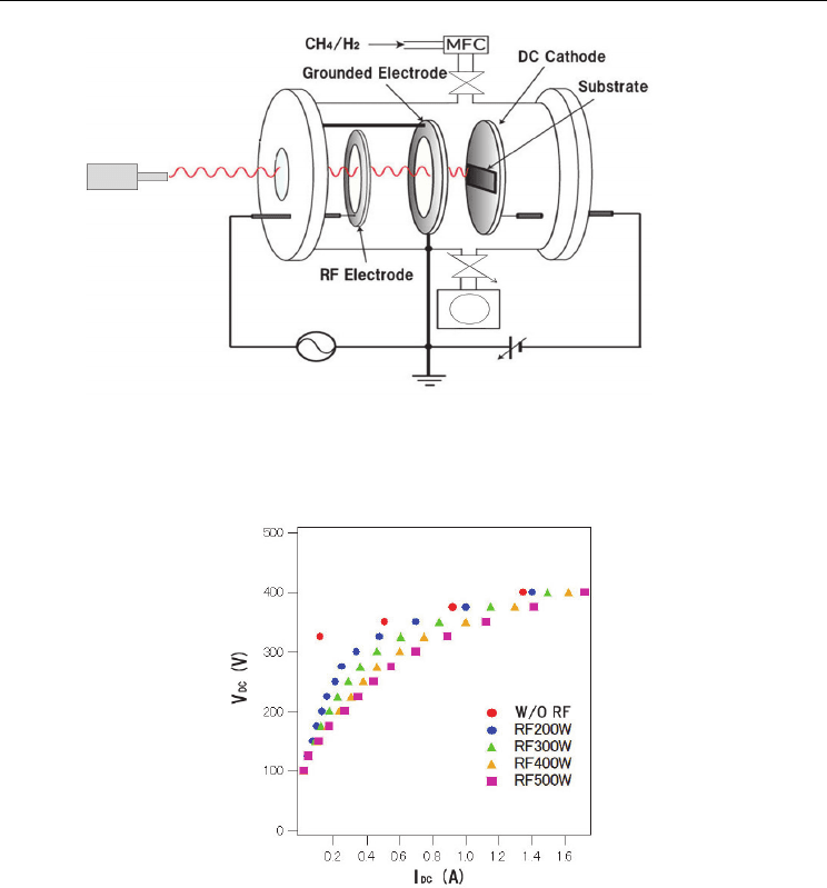
2.1 Experimental system of RF-DC PE-CVD
Figure 1 shows the schematic of the RF-DC plasma CVD system. Three electrodes (i. e., a
13.56 MHz RF electrode, a grounded electrode, and a DC cathode) are vertically fixed
parallel to each other in a vacuum chamber. The distance between the RF and the grounded
electrode is 10 mm, and that between the DC cathode and grounded electrode is 15 mm. The
DC cathode, which is round in shape with 110 mm in diameter, having a hole at the center,
also plays the role of a substrate holder. A substrate up to 75×75 mm
2
can be mounted on
the cathode. An RF plasma is generated between the RF electrode and the grounded
electrode, while a DC plasma is generated between the DC cathode and the grounded
electrode. The grounded electrode is ring-shaped to facilitate passage of a part of the RF
generated plasma into the space of DC discharge. The inside of the ring is covered with a
mesh or wires, or is left without them. RF power induces not more than 500 W to the RF
electrode. a negative bias not more than 650 V is applied to the cathode electrode. Substrate
temperature is measured with a pyrometer at the backside of the substrate or on the surface
of the substrate through the center hole of the RF electrode.
2.2 Features of RF-DC plasma
Figure 2 shows the relationship between the voltage and the current of DC discharge with
and without RF plasmas in pure hydrogen, measured in the RF-DC plasma CVD system.
The current shows average values measured with increasing and decreasing voltage. The
firing potential without RF plasma was approximately 300 V, which decreased to a voltage
of around 100 V with RF plasma. The discharge voltage decreased from 350 V to 270 V
Growth of Vertically Aligned Carbon Nanotubes by RF-DC Plasma Chemical Vapor Deposition
5
Fig. 1. Schematic of the RF-DC plasma CVD system. RF plasma and DC plasma are
generated between RF electrode and grounded electrode and between DC cathode and
grounded electrode, respectively.
Fig. 2. Relationship between voltage and current of DC discharge with and without RF
plasma in pure hydrogen.
at 0.5 A current, and from 380 V to 340 V at 1.0 A current by the generation of RF plasma
with a power of 500 W. The impedance of DC discharge decreased with the increase of RF
power.
In DC plasma, arcing occasionally occurs at cusped points on the surface of an electrode
because high electric fields are formed there. During the fluctuation of plasma state, the
electric field at a cusped point accidentally exceeds the value of arcing induction. In order to
prevent arcing, DC voltage should be lowered to within the limit of discharge continuation.
Thus, stable DC discharge with less arcing is expected under the condition of low
impedance.
Carbon Nanotubes – Polymer Nanocomposites
6
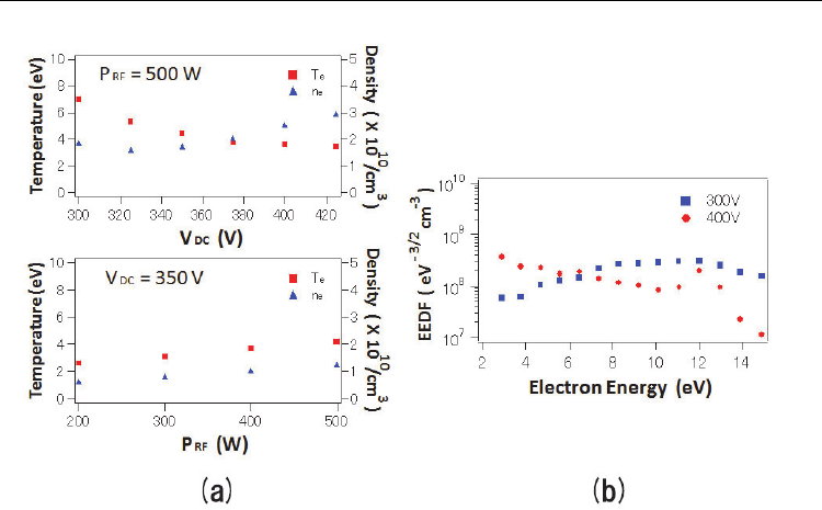
Fig. 3. Features of RF-DC plasma. (a) DC voltage and RF power dependence of electron
temperature (T
e) and electron density (ne). (b) Electron energy distribution function (EEDF)
for DC voltage of 300 V and 400 V with RF power of 500 W.
The plasma diagnostics of RF-DC plasma was carried out by the method of Langmuir
probe. The tip of Langmuir probe was a tungsten wire of 0.3 mm in diameter and 10 mm
in length. The probe was set parallel to the cathode surface at a distance of 10 mm and its
longitudinal center at 10 mm from the center axis of electrodes. The diagnostic result is
shown in Fig.3. Figure 3(a) shows the dependence of electron temperature and density on
DC voltage under a constant RF power of 500 W (upper), as well as their dependence on
RF power under a constant DC voltage of 350 V (lower). The electron temperature
decreases with increase of DC voltage or with decrease of RF power. In other words,
higher electron temperature is obtained under a larger influence of RF plasma. Electron
density gradually increases with increase in DC voltage and RF power. Typical electron
energy distribution function (EEDF) for DC voltage of 300 and 400 V with RF power of
500 W is shown in Fig.3(b). Comparatively higher energy electrons exist under the
condition of higher RF power, i. e., they increase with the increase in ratio of RF power to
DC discharge voltage. Because the binding energy of H-H and C-H is 4.5 eV and 4.3 eV,
respectively, electrons of energy higher than these values promote the dissociation of
hydrogen and hydrocarbon molecules in a plasma. Active species for the growth of CNTs
are produced by such energetic electrons.
2.3 Growth of vertically aligned CNTs
Iron foil substrates of 0.2 mm thickness, which had been ultrasonically cleaned in ethanol,
were fixed onto the cathode electrode. They were pretreated before CNT growth in a pure
hydrogen plasma under a DC voltage of 350 V with RF power of 500 W and pressure of 2200
Pa for 15 min. Methane gas was added to hydrogen by 20% under the same operating