Труды Всемирного конгресса Международного общества солнечной энергии - 2007. Том 2
Подождите немного. Документ загружается.


Proceedings of ISES Solar World Congress 2007: Solar Energy and Human Settlement
952
absorbed by the refrigerant. The refrigerant directly
expanding inside the copper coil transfers the absorbed
thermal energy to the condenser, as well as makes the PV
cells operating at low and steady temperature to improve
the PV efficiency of the system.
Fig. 1: Cross-section view of a PV evaporator module.
2. MATHEMATICAL MODEL
The distributed model has been widely used to describe the
behavior of the dry expansion evaporator in the passed
decades (MacArthur et al., 1989; Wang et al., 1991; Tso et
al., 1999).
In this paper a distributed and steady model based on
homogeneous flow is established to evaluate the
performance of the PV evaporator. The temperature drop of
the refrigerant due to the pressure drop in the two-phase
flow region is taken into account in the model. To simplify
the calculation, the following assumptions are necessary:
(1) The temperature difference of the glass cover along the
flow direction is neglected, i.e. the temperature distribution
of the glass cover is considered to be a one-dimension
problem.
(2) The temperature of every PV cell is considered to be
uniform and the PV cell is located in the center of the
control volume of the basic panel.
(3) The contract thermal resistance of the solar collector
which is composed of the copper coil, aluminum panel and
aluminum alloy panel is neglected, i.e. the temperature of
the three elements is considered to be uniform in one
cross-section.
(4) The refrigerant flow inside the evaporator is considered
as one-dimensional homogeneous flow. The liquid and
vapor refrigerant have the same average cross-sectional
velocity, i.e. the slip between liquid and vapor is neglected.
(5) The liquid and vapor are in saturated thermal
equilibrium and the pressure of the liquid and vapor are
equal in one cross-section.
(6) The kinetic energy and potential energy are ignored in
the energy equation.
With the listed assumptions, a distributed model of the PV
evaporator with six equations can be obtained as follow:
2.1 Heat Balance Equation of the Glass Cover
(
)
(
)
()
()()( )()
0
1
=∂∂++
−++−+−
+−+−
yTlG
TTTT
TTTT
λβ
ααξααξ
αα
(1)
2.2 Heat Balance Equation of the PV Cells
()
()()
()
0
GG TT
TT R
τβ τη α α−+ + −
+− =
(2)
3.3 Heat Balance Equation of the Solar Collector
()( )
()
()
()
()
()()
11
0
GA ATT
AT T R AT T AT T R
lA T y lA T z
τβ ξ α α ξ
ξα
λλ
−+ + − −+
−+−+−
+∂∂+∂∂=
(3)
3.4 Conservative Equations of the Refrigerant
()
0z =∂∂ uρ
(4)
where
ρ is the average density defined as:
()()
xx ρρρρρ −+= 1
()
zpPzuu ∂∂−∂∂−=∂∂ zρ
(5)
()
(
)
AuqπDh ρ
=∂∂ z
(6)
where
h is the average enthalpy of the refrigerant, which
is decided by the vapor quality and the specific enthalpy of
liquid and vapor refrigerant:
()
hxxhh −+= 1
.
3 SOLAR COLLECTOR TECHNOLOGIES AND SYSTEMS
953
In order to solve the above equations, the auxiliary
empirical correlations of the heat transfer coefficients for
the inside and outside surface of the glass cover are
necessary. An empirical correlation proposed by Müller-
Steinhagen and Heck [7] is employed in this paper to
calculate the frictional pressure of the refrigerant. The local
heat transfer coefficient of the refrigerant in two-phase flow
is calculated from a correlation which is based on the
Lockhart-Martinelli parameter [4].
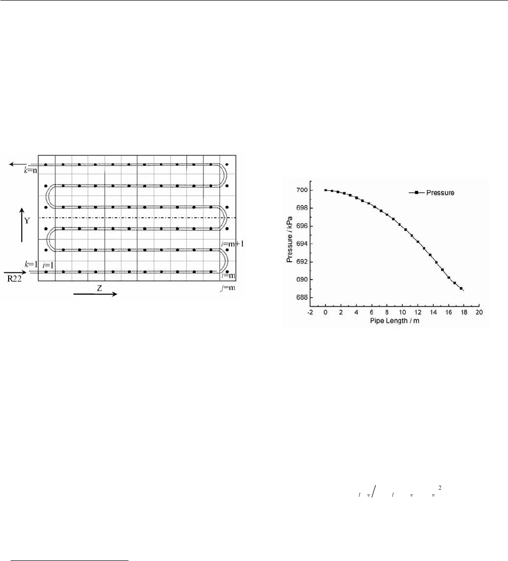
Fig. 2: Cell division of the PV evaporator.
To obtain a solution for the problem, the solar collector
should be divided into small cells. Two types of divisions
have been shown in Fig. 2, one of which is according to the
flow direction and another is according to the Z and Y
direction. With the two types of divisions, the temperature
of the solar collector have two different form of expressions:
1
,
+n
ic
T and
1
,,
+n
kjc
T . To facilitate the programming procedure,
transformation between the two different expressions is
necessary. The matrix
()
∏
= ikj,
according to the coil
circuitry of the evaporator can be used to realize the
transformation
.
With the division shown in Fig. 2, the model can be solved
based on the implicit finite difference method.
3. RESULTS AND ANALY SIS
In order to investigate the behavior of the PV evaporator, a
numerical simulation program is written in C++ language.
The boundary conditions for the program are shown as
follow:
Solar irradiation in normal direction: 600 (W/m
2
)
Ambient Temperature: 278.15 (K)
Inlet pressure: 700 (kPa)
Mass velocity: 100 (kg/m
2
s)
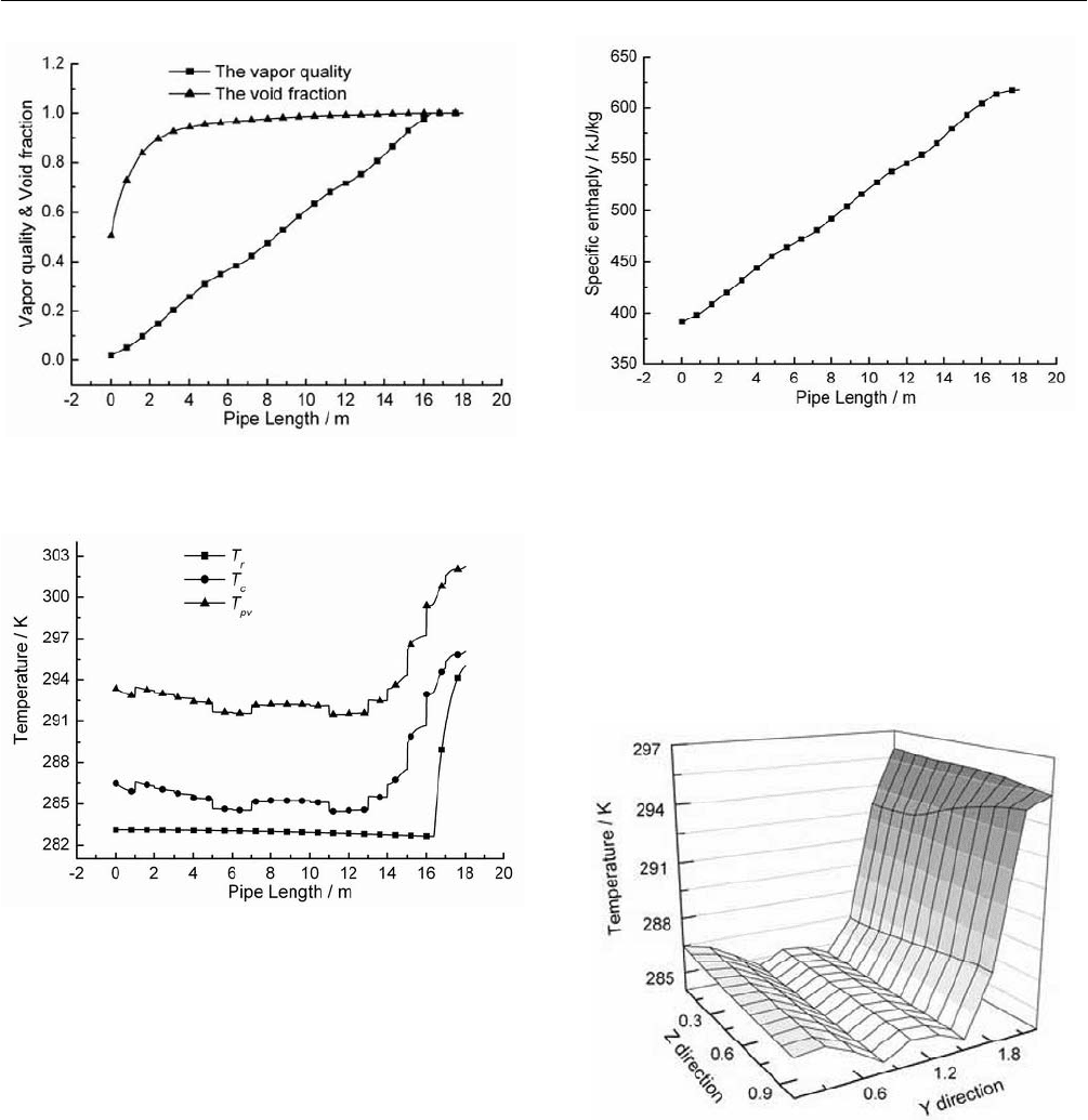
The pressure distribution along the copper coil in the
evaporator is given in Fig. 3. The frictional pressure drop
increases with the vapor quality in two-phase flow region
and declines in dry-out region (x>x
d
) [8]. Hence, the slope
of the pressure along the pipe escalates in two-phase region
and drops where the pipe length is about 16.2 m as shown
in the figure.
Fig. 3: The pressure distribution along the copper coil.
The distribution of the vapor quality and void fraction of
the refrigerant can also be given by our program. A s can be
observed in the figure, the vapor quality varies almost
linearly in two-phase flow region and keeps constant in the
superheat region. The void fraction increases rapidly from
0.5 to 0.9 where the pipe length L<3 m. It is because that
the void fraction is more sensitive with small value of the
vapor quality according to the following correlation:
()
[]
dxxd ρρρρρα +−>=<
(18)
The temperatures distribution of the PV cells, solar collector
and refrigerant along pipe length are illustrated in Fig. 5. As
can be seen, the temperature of the refrigerant keeps nearly
const with a tiny drop in two-phase flow region and increases
rapidly in superheat region due to the small heat capability of
the vapor refrigerant. The area of the superheat region is
about 10% of the total area. The degree of the superheat is
about 12 K. The temperatures of the solar collector and PV
cells show a similar trend as the refrigerant.
Proceedings of ISES Solar World Congress 2007: Solar Energy and Human Settlement
954
Fig. 4: The distribution of the vapor quality and void
fraction.
Fig. 5: The temperatures distribution.
The distribution of the average specific enthalpy of the
refrigerant is depicted in Fig. 6. The specific enthalpy of
the vapor and liquid refrigerant is nearly const in two-phase
flow region. Hence the average specific enthalpy can be
considered as a linear function of the vapor quality in this
region according its definition. As shown in the figure, the
average specific enthalpy rises more slowly in superheat
region than that in two-phase flow region which is because
of the smaller heat transfer coefficient of the vapor
refrigerant.
Two-dimensional temperature distribution of the solar
collector is depicted in Fig. 7. The temperature difference
along Z direction is much smaller than that along Y
direction. Because of the frames of every evaporator module,
Fig. 6: The distribution of the average specific enthalpy.
the effective thermal absorbed area for the marginal nodes
along Z direction is a little smaller than that of the other
nodes. Hence, the temperature shows a wavy trend in
two-phase flow region. The temperature along flow
direction in superheat region may drop due to the heat
conduction of the nodes with the others in the two-phase
flow region along Y direction.
Fig. 7: Two-dimensional temperature distribution of the
solar collector.
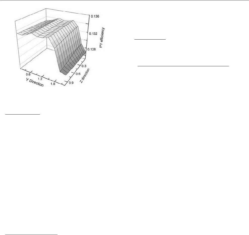
As shown in Fig. 8, two-dimensional distribution of
the PV efficiency experiences an opposite trend with
the temperature of the solar collector and PV cells. A
wavy changing in two-phase flow region and a sharp
drop in superheat region can also be observed from the
figure.
3 SOLAR COLLECTOR TECHNOLOGIES AND SYSTEMS
955
Fig. 8: Two-dimensional distribution of the PV efficiency.
4. CONCLUSIONS
A specially designed PV evaporator, which combines two
solar technologies into a system for dual production of
electricity and thermal energy, is presented in this paper. A
steady model based on the distributed parameter is
established to describe the behavior of the evaporator. With
the model, nearly linear distribution of the vapor quality
and average enthalpy of the refrigerant can be obtained.
The temperature difference of the refrigerant, solar
collector and PV cells in two-phase flow region is much
smaller than that in superheat region. The area of the
superheat region is about 10% of the total area when the
superheat degree can reach 12 K. The void fraction is more
sensitive with tiny changing of the vapor quality in the
region where the vapor quality is small.
5. ACKNOWLEDGMENTS
The work in this paper was sponsored by the National
Natural Science Foundation of People’s Republic of China
(No. 50478023) and Anhui Province Nature Science
Foundation of China (No. 070414161).
6. REFERENCES
(1) Kern Jr. E. C., Russell M. C., “Optimization of
photovoltaic/thermal collector heat pump systems”,
International Solar Energy Society meeting
, Atlanta,
GA, USA, 1979, pp.1870-1874.
(2) Sadasuke Ito, Nakatsu Miura, Jin Qi Wang, “Heat
pump using solar collector with photovoltaic modules
on the surface”, Journal of Solar Energy Engineering,
1997, Vol.119, pp.147-151.
(3) J.W. MacArthur, E.W. Grald, “Unsteady compressible
two-phase flow model for predicting cyclic heat pump
performance and a comparison with experimental data”,
International Journal of Refrigeration, 1989, Vol.12,
pp.29-41.
(4) H. Wang, S. Touber, “Distributed and non-steady-state
modeling of an air cooler”, International Journal of
Refrigeration, 1991, Vol.14, No.2, pp.98-111.
(5) X. Jia, C.P. Tso, P. Jolly, Y.W. Wong, “Distributed
steady and dynamic modeling of dry-expansion
evaporators”, International Journal of Refrigeratio,
1999, Vol.22, pp.126-136.
(6) Duffie JA, Beckman WA. “Solar engineering of
thermal processes”, 2nd Edition. New York: Wiley;
1991.
(7) Müller-Steinhagen H., Heck K., “A simple friction
pressure drop correlation for two-phase flow in pipes”,
Chemical engineering and processing , 1986, Vol. 20,
No.6, pp.297-308.
(8) M.B. Ould Didi, N. Kattan, J.R. Thome, “Prediction of
two-phase pressure gradients of refrigerants in
horizontal tubes”, International Journal of
Refrigeration, 2002, Vol. 25, No.7, pp.935-947.

APPLICATION OF SOLAR HEATING SYSTEM IN BIOGAS PRODUCTION
Rong Dai
1,2
, Chang Chun
2
, Zhibin Xu
1
, Xiaobing Liu
1,2
, Ζhifeng Wang
2
1
Himin Solar Energy Group Co., Ltd, Dezhou, Shangdong 253090, P.R. China
2
Institute of Electrical Engineering, Chinese Academy of Sciences, Beijing 100080, P.R.China
ABSTRACT
In the biogas production from agriculture manure by
anaerobic digestion, it is necessary to keep the bioreactor
optimum and steady temperature. The optimum condition
usually can not be achieved automatically in winter in
North China. The solar water heating system using
evacuated tubes with auxiliary electrical heater was
adopted to charge the thermal energy to the bioreactor,
which made the bioreactor work regularly. It was
experimentally investigated that the required solar
collector area, the production amount of the biogas and
the auxiliary electrical power at the temperature of 15 , ć
20 and 25 of the ććbioreactor. The biogas production
system has been running steadily for two years. As a
result, when the daily average solar flux was 13.2 MJ/m
2
and the temperature of a
bioreactor of 6m
3
was optimized
to be at (20±1) in the coldest month in Beijing, 3.85mć
2
of solar collector area was required, and 0.2-0.25m
3
/m
3
d
of biogas can be obtained.
1. INTRODUCTION
Biogas can be produced from agriculture manure by
anaerobic digestion. This technology has many benefits in
view of environment, agriculture and sustainability[1,2].
Biogas plants for family have been extensively used in
most of the farms in China. Temperature is an important
factor that affects the performance of anaerobic
digestion[3]. This optimum condition for the anaerobic
digestion usually can not be achieved automatically due to
harsh cold climatic conditions. So electricity, oil or part of
the biogas produced in the process is used to keep the
reactor at the desired temperature. But using such
high-level fuel is very uneconomical[4]. In the meantime,
there is enough solar radiation in winter in North China, it
is possible to use a solar collector combined with a heat
exchanger to heating manure in the bioreactor. So the
bioreactor can achieved an optimum and steady condition
to produce biogas. As a rule, it is needed to input more
solar thermal energy into the bioreactor to keep the
bioreactor at higher temperature. The bioreactor
temperature is kept at 35 or 54ćć[5], at which more
biogas can be produced. But higher temperature of the
bioreactor will lead to an increase in the original
investment. So it is necessary to find the optimum
temperature of the bioreactor in view of cost.
2. DESCRIPTION OF SYSTEM
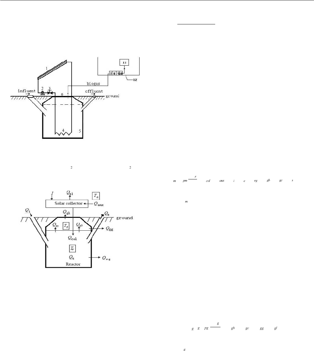
Figure 1 shows the schematic diagram of the proposed
system. Solar collectors combined with a heat exchanger
was used to heating the manure in the bioreactor, and
increased the bioreactor temperature to an optimum value
in a steady condition. In order to keep the system run in
steady condition, the control unit was adopted. If there was
not enough solar thermal energy input into the bioreactor
(e.g. cloudy), or the water temperature in solar tank is
below 45 ,ć the solar heating system stops working, then
the auxiliary electrical heating system starts to supply the
3 SOLAR COLLECTOR TECHNOLOGIES AND SYSTEMS
957
heat to the bioreactor. The bioreactor was positioned under
the ground. The biogas produced from the bioreactor was
transported to the kitchen by the designed pipe for cooking.
The heat balance of the system was shown in Fig. 2.
Fig. 1: Schematic of the system configuration.
1 solar collector; 2 pump; 3 control valve; 4 heat exchanger; 5 bioreactor;
6 movable cover of bioreactor; 7 H
O removal; 8 manometer; 9 H S removal
vessel; 10 gas counter; 11 biogas cooker; 12 kitchen
Fig. 2 Overall heat balance diagram.
The nomenclatures are as the follows.
Q
sl
losses from the solar collector, Q
i
heat losses from the
influent (W),T
g
the biogas temperature ( ), ć Q
aux
auxiliary
heat add to the reactor (W), Q
gl
heat losses from biogas
volume to ambient (W), Q
el
heat losses from the effluent
(W), T
r
the temperature of the manure (ć), T
a
ambient
temperature (ć), Q
s
inner energy of manure (W), Q
gc
heat
losses by convection from the liquid to biogas (W), Q
gb
heat losses from the liquid via biogas bubbles (W),
I
overall radiation amount per day, Q
gg
heat losses from
biogas volume to ground (W), Q
col
useful heat gain rate
from the collector (W);
2.1 The Bioreactor
In the proposed system, the volume of the bioreactor under
the ground was 6 m
3
in order that the biogas produced can
be enough for cooking of a family of three people. The
movable cover of the reactor is installed above the ground.
The raw material adopted agriculture manure. The
concentration of the water in the manure is 10%, and the
effective volume of the manure fed to the bioreactor is 5.2
m
3
. The other space (i.e 0.8m
3
) can hold the biogas
produced. The manure was fed to the system every three
days. The amount of manure added to the reactor was equal
to that of manure withdrawn from it.
It is assumed that the manure in the bioreactor is always
well mixed at a uniform temperature. The energy balance
equation for the bioreactor can be written as:
dT
VC Q Q Q Q Q Q Q Q
dt
ρ =+−−−−−+
˄1˅
where:
ρ
the density of the manure (kg/m
3
), V effective
reactor volume (m
3
), C
pm
specific heat of manure(Jg kg
-1
K
-1
),
t time (s), T
r
the temperature of the manure˄ć˅, Q
col
useful
heat gain rate from the collector (W), Q
aux
auxiliary heat
added to the reactor (W), Q
i
heat losses from the influent
(W), Q
e
heat losses from the effluent (W), Q
rg
heat losses
from the manure to the ground (W), Q
gb
heat losses from
the liquid via biogas bubbles (W), Q
gc
heat losses by
convection from the liquid to biogas (W), Q
s
inner energy
of manure (W).
Assuming that the biogas temperature in the enclosure is
uniform, its heat balance equation can be written as:
dT
VC Q Q Q Q
dt
ρ =+−−
˄2˅
where
ρ the density of biogas (kg/m
3
), V
g
the volume of
biogas(m
3
), C
pg
the specific heat of the biogas (Jgkg
-1
K
-1
),
T
g
the biogas temperature (ć), t time (s), Q
gb
heat losses
from the liquid via biogas bubbles (W), Q
gc
heat losses by
convection from the liquid to biogas (W), Q
gg
heat losses
from biogas volume to ground (W), Q
gl
heat losses from
biogas volume to ambient (W).

Proceedings of ISES Solar World Congress 2007: Solar Energy and Human Settlement
958
2.2 Solar Collector
There are two solar collectors used in the system. They
were
fabricated at the tilt angel of 45
o
and faced to the south
direction. One solar collector was made up of 18 vacuum
tubes with 58mm in diameter and 1.9m in length. The
distance between two vacuum tubes is 21mm. The overall
area of one collector is 2.5m
3
. At the meantime, there is an
auxiliary electrical heater system with the power of 1500W
in the water tank. The volume of the water tank is 163L.
It can be assumed that the temperature distribution of the
collector and the water tank is linear, and their average
temperature are
T and T , respectively. The thermal
capacity of the collector can be neglected since it is very
small
[6]
. The obtained energy from the solar collectors can
be presented by the following equation,
()'[()]mC T T A F S U T T−= − −
(3)
m
is the flow rate of the water˄kggs
-1
˅, C specific heat
of water, (Jgkg
-1
K
-1
), T
f,o
water outlet temperature from
the solar collector, ( )ć ˈT
f,i
water inlet temperature to the
solar collector, ( ),ć A
c
the solar collector area (m
2
), 'F the
collector efficiency factor,
S absorbed radiation(W/m
2
)ˈ
U
L
overall heat loss coefficient from the solar collector to
environment, (Wm
-2
K
-1
)ˈT
m
average temperature of the
water in the solar collector, T
a
ambient temperature( )ć .
2.3 Heat Exchanger
The heat exchanger is coiled by copper pipe with the
diameter of 16mm. This design is simple and the cost is
very low. The heat provided by the heat exchanger can
compensate for the heat loss from the bioreactor. The
logarithmic mean temperature difference for the heat
exchangeris calculated from the heat exchanger[7].
2.4 The Control System
The purpose of the control system is to keep the bioreactor
temperature constant. When the temperature of the
bioreactor was below the given temperature, the water
pump started to run and the heat can be input into the
bioreactor by the hot water from the solar collectors. The
pump stopped working when the temperature achieved the
given value. If the temperature of the water in the tank can
not reach the needed value, the auxiliary electrical heat
system started to work until the temperature of the tank
reached up to the needed value. The designed temperature
of the sensor can be adjusted ranging from 0 to 80 ,ćć
which can satisfy different digestion temperature for the
bioreactor.
3. EXPERIMENT METHOD
Because the original investment needs to be reduced and
the biogas produced can be enough for daily use for
farmers, an optimum temperature of bioreactor must be
found in the experiments. For this purpose, the experiments
at the temperatures of 15ć, 20ć and 25 ć were carried
out on the abovementioned proposed system.
3.1 The Digestion Temperature
The experiments were carried out at the digestion
temperatures of 15ć, 20ć and 25ć, respectively.
3.2 The Material of Digestion and Inoculant
The material of the digestion was the cattle manure that
came from the cattle farm near the laboratory. By the test,
the TS is16.98%, the VS is78.02% .The inoculant is gained
from swine manure. TS is 10.43% ,VS is 72.22 %.
4. RESULTS AND DISCUSSION
4.1 Measurement of Material Before and after Digestion
Test unit˖250ml, inoculantǃ60g cattle manureˈadd liquid
manure to1000ml˗
Comparision unit˖250ml, inoculant, add liquid manure
to1000ml˗
Digestion temperature:
(20+1)ć, pH is kept at 7.
Table 1 shows the value of TSǃVS before and after the
digestion. It can be seen from Fig. 1 that the concentrations
of TS and VS in anaerobic manure were very low. Based on
3 SOLAR COLLECTOR TECHNOLOGIES AND SYSTEMS
959
the color of the blaze of the biogas[8], we can know that
the content of the methane varied from 55% to 65%.
TABLE1: THE VALUE OF TS ǃ VS BEFORE AND
AFTER THE DIGESTION
BEFORE
DIGESTION
AFTER
DIGESTION
TS/% VS/% TS/% VS/%
Test 8.25 80.91 4.85 78.12
Comparison 4.85 79.37 3.57 78.49
4.2 Relationship Between Biogas Production and Digestion
Temperature
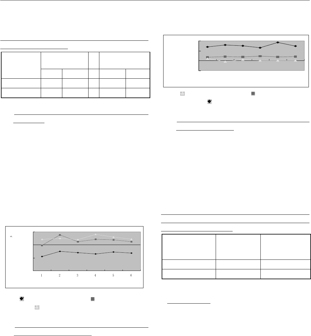
It also can be seen from Fig. 3 that in the range of 15ć-
25ć, more production biogas can be produced at higher
fermentation temperature. In the rural area of China, the
daily use of biogas for one person is about 0.4 m
3[9]
, so the
biogas production of 20ć can meet the need of a family of
three people. The production of the biogas at 25 ćis
0.0966m
3
/d higher than that at 20ć. The heat value of
CH
4
is 35.882 MJ/m
3
. Assuming that CH
4
accounts for 65%
of the biogas, the difference of energy between the biogas
production in 20ć and 25ć is 2.25MJ.
day
˄
d
˅
biogas production
˄
m /d
˅
Fig. 3:
biogas production at 15 ,ć biogas production at
20 ć
biogas production at 25ć.
4.3 Relationship Between Radiation, Ambient Temper-
ature and Consumed Electricity
As shown in Fig. 4, the relationship between the consumed
electricity and solar irradiation was not linear, because the
consumed electricity is affected by several factors,
including water circulation by the pump, the electrical
consumption of the auxiliary heat system and the ambient
temperature. If the bioreactor temperature and the collector
area are kept constant, higher solar radiation can lead to
less electrical consumption.
day
˄
d
˅
value
Fig. 4:
ambient temperature( ),ć consumed electricity
˄kWh˅ˈ
radiation (MJ/m
2
).
4.4 Relationship Between Digestion Temperature and
Area of Solar Collector
The average daily solar radiation is 13.2 MJ/m
2
in the
coldest month in Beijing. The relationship between the
digestion temperature and the area of the solar collector is
shown in table 2. If the efficiency of the solar collector is
0.44, increasing 1.05m
2
area of the solar collector will lead
to the energy increasing to 6.09 MJ at the same ambient
temperature.
TABLE2: RELATIONSHIP BETWEEN THE TEMPE-
RATURE OF THE DIGESTION AND THE AREA OF
THE SOLAR COLLECTOR
FORMEMTATIO
N TEMPERTURE
˄ć˅
SOLAR
COLLECTOR
AREA˄m
2
˅
BIOGAS
PRODUCTION
˄m
3
/m
3
·d˅
20 3ˊ85 0.2-0.25
25 4ˊ91 0.2-0.27
5. CONCLUSIONS
In order to reduce the original investment of the solar
system and to meet the daily use of the farmers in the
meantime, a biogas production system was proposed.
Experiments were carried out at the bioreactor reactor of
15ć, 20ć and 25ć. The relationship between the biogas
production, the area of the collector and the electrical
consumption was built. The main conclusions are as
follows.
(1) In the same condition, the efficiency of biogas

Proceedings of ISES Solar World Congress 2007: Solar Energy and Human Settlement
960
production in 20 is higher than the efficiency in 25 . So ćć
the system deserves to popularize in the rural areas.
(2) Using solar thermal energy or other renewable sources
to heating the bioreactor is a good alternative, because
these sources are environmentally friendly. However, there
are still significant gaps between the costs of these sources
and that of traditional ones[10]. We give emphasis this
view to next research.
6. REFERENCES
(1) Van Velsen A F M; Lettinga G, “Effect of Feed
Composition on Digester Performance”. In: Anaerobic
Digestion (Stafford D A; Wheatley B I; Hughes D E,
eds). Applied Science Publishers Ltd., London,
UK.,1980
(2) De Baere L, “Anaerobic Digestion of Solid Waste”:
stateof-the-art. Water Science and Technology, 41 (3),
283-290, 2000
(3) MengjinZhou,“Biogas Practical Technology”[M], Beijing,
Chemical Industry Press, 2004
(4) Axaopoulos P; Panagakis P; Tsavdaris A; Georgakakis
D (2001). “Simulation and Experimental Performance
of A Solar-heated Anaerobic Digester”, Solar Energy,
70 (2), 155-164
(5) Zhenghong Yuan, Chuangzhi Wu, Longlong Ma,
“Principle and The Use of Biomass Technology”[M],
Beijing, Chemical Industry Press,2005.
(6) Wenhua Xi, “Solar Practical Engineering Technology”
[M], Lanzhou University press, 2001
(7) Dahl S D; Davidson J H, “Comparison of Natural
Convection Heat Exchangers for Solar Water Heating”,
Proceedings of Solar, 95. The 1995 American Solar
Energy Society Annual Conference, 15-20 July,
Minneapolis, MN, USA ,1995
(8) Yunhua Jiang, et al., “The Judgment of Methane
Gas Content by Flame Color”[J], China Gas, 1983,(3),
28
(9) Zeyang Wang, “Rural Methane Practical Technology”
[M], Shandong: Petroleum university press, 2004
(10) Sims R E H, “Renewable Energy: A Response to
Climate Change”, Solar Energy, 2004, 76, 9-17

THE SOLAR ENERGY MULTIPURPOSE ADJUSTABLE CONTROL GLASSHOUSE
Song Ziling, Zhong Xianliang, Zhang Lixin
LIAONING technology university,
Fuxi city Liaoning province,123000
SONGZILING-163@163.com
ABSTRACT
The glasshouse, which can be used to plant, stockbreeding
and the low temperature dryness industry, even though
built in temperate zone and cold zone also can adjust
various temperature and humidity to meet the request of
production. Its concrete measures as follows: Adjust
glasshouses layout and extend its scope for settling to
decrease area of dissipation and increase the area of usage.
Make use of efficient adopt light lead pieces and make
them vertical plane alignment and face to south, under the
no sun follow device situation make the sun light from
sunrise to sunset 100% can be collected, and from various
angle spread to leaf, receptacle, stem etc. to improve the
output and quality of agricultural product greatly. Make a
part of sunlight shoot straight at soil, making use of the
characteristics which the heat capacity of soil is larger to
save heat, make sure the room temperature invariable in
night and rainy day. The temperature and humidity may
regulate arbitrarily, keep plants away from various plant
diseases and pests. When the Solar Energy is used for
drying technique, regulate the temperature near to 100ć,
makes sunlight shoot straight at drying thing surface.
Make solar energy drying technique enter the high-effect
times.
1. INTRODUCTION
The Solar Energy Multipurpose Adjustable Control
Glasshouse technology supply solar energy high efficient
used, and be the same with various purpose. This is solar
energy utilizing technology, and is all-purpose
establishment for the vegetable, esculent mushroom, animal
breed, and peasant byproduct dryness.
Since 1980s, the saving energy solar light glasshouse, that
is Chinese protect soil establishment, gain ground in north
area. Ten year recently, it was more used in other area of
China. The saving glasshouse area is enlarging, and
obtaining remarkable economical, social, ecological benefit.
But such glasshouse utilized lower-efficient solar energy.
Mostly, these cause are that the temperature of glasshouse
is lower in winter, only 20ć in day, 8ć in nighttime, so as
to the more crop cannot get high yield. In freezing area, the
glasshouse cannot help but use assistant heat. In a word,
current solar light glasshouse has not extrusive effect to
save energy, and has not width applying field, and has more
energy saved in newly glasshouse.
The designing of the solar energy multipurpose adjustable
