Taylor D.A. Introduction to marine engineering
Подождите немного. Документ загружается.

50
Diesel engines
Exhaust
gas
from
the
engine
is
passed into
a
constant-pressure
receiver
and
then into
the
turbochargers.
Scavenging
is
uniflow,
and
electrically
driven
auxiliary
blowers
are
automatically
started during
low-load
operation.
Lubricating
oil is
supplied
to the
various bearings
and
also
to the
pistons
for
cooling.
Cylinder
oil is
supplied
via
lubricators
from
a
high-level
service tank.
A
separate
lubrication system
is
provided
for the
camshaft
bearings
to
prevent contamination
of the
main lubricating
oil
system.
Fresh water cooling
is
provided
for the
cylinder
jackets, cylinder
covers
and
exhaust
valves.
The
engine
is
designed
to run on
diesel
oil or
heavy
fuel
oil.
An
electronic
governor
is
provided
as
standard.
Piel
stick
The
Pielstick
PC
series engines
are
single-acting, medium-speed,
four-stroke
reversible types. Both in-line
and
V-configurations
are
available.
The
running gear, being
a
trunk-type engine,
is
made
up of
the
piston
and the
connecting
rod
which
joins
the
single-throw
crankshaft.
The
arrangement
of a PC4
engine
is
shown
in
Figure 2.30.
The
crankcase
and
frame
are
constructed
from
heavy plate
and
steel
castings
to
produce
a
low-weight rigid structure.
The
crankshaft
is
underslung
and
this arrangement confines
all
stresses
to the
frame
structure.
The
crankshaft
is a
one-piece
forging
and the
connecting rods
are
H-section
steel stampings.
The
one-piece cylinder head
contains
two
exhaust
and two
inlet
valves
together
with
a
starting
air
valve,
a
relief
valve,
indicator cock
and a
centrally
positioned
fuel
injector.
Exhaust-gas-driven
turbo-chargers operating
on the
pulse
system
supply
pressurised
air to the
engine cylinders.
Bearing lubrication
and
piston
cooling
are
supplied
from
a
common
system.
The
engine
has a dry
sump
with
oil
suction being taken
from
a
separate tank.
The
cylinder
jackets
are
water-cooled together
with
the
cylinder heads
and
the
exhaust
valve
cages.
The
charge
air
cooler
may be
fresh-water
or
sea-water
cooled
as
required.
Fuel
injection uses
the
jerk pump
system,
and a
Woodward-type
hydraulic
governor
is
used
to
control engine speed.
Later
versions
of the PC
series engine
are
described
as
PC20
and
PC40
and
have somewhat increased scantlings.
Operating
procedures
Medium-
and
slow-speed diesel engines
will
follow
a
fairly
similar
procedure
for
starting
and
manoeuvring.
Where reversing gearboxes
or
Diesel
engines
51
controllable-pitch
propellers
are
used then engine reversing
is not
necessary.
A
general procedure
is now
given
for
engine operation
which
details
the
main
points
in
their correct sequence. Where
a
manufactur-
er's
instruction
book
is
available
this
should
be
consulted
and
used.
Preparations
for
standby
1.
Before
a
large diesel
is
started
it
must
be
warmed through
by
circulating
hot
water through
the
jackets, etc. This
will
enable
the
various
engine parts
to
expand
in
relation
to one
another.
2.
The
various
supply
tanks,
filters,
valves
and
drains
are all to be
checked.
3.
The
lubricating
oil
pumps
and
circulating
water pumps
are
started
and all the
visible returns should
be
observed.
4. All
control equipment
and
alarms should
be
examined
for
correct
operation.
5.
The
indicator cocks
are
opened,
the
turning gear engaged
and the
engine
turned
through
several complete revolutions.
In
this
way any
water
which
may
have collected
in the
cylinders
will
be
forced out.
6. The
fuel
oil
system
is
checked
and
circulated
with
hot
oil.
7.
Auxiliary
scavenge blowers,
if
manually
operated,
should
be
started.
8.
The
turning gear
is
removed
and if
possible
the
engine should
be
turned over
on air
before closing
the
indicator cocks.
9. The
engine
is now
available
for
standby.
The
length
of
time
involved
in
these preparations
will
depend upon
the
size
of the
engine.
Engine
starting
1.
The
direction handle
is
positioned ahead
or
astern.
This
handle
may
be
built
into
the
telegraph reply lever.
The
camshaft
is
thus
positioned
relative
to the
crankshaft
to
operate
the
various cams
for
fuel
injection,
valve
operation, etc.
2.
The
manoeuvring
handle
is
moved
to
'start'.
This
will
admit
compressed
air
into
the
cylinders
in the
correct sequence
to
turn
the
engine
in the
desired
direction.A
separate
air
start button
may be
used.
3.
When
the
engine
reaches
its firing
speed
the
manoeuvring
handle
is
moved
to the
running position. Fuel
is
admitted
and the
combustion
process
will
accelerate
the
engine
and
starting
air
admission
will
cease.
52
Diesel
engines
Engine
reversing
When
running
at
manoeuvring
speeds:
1.
Where
manually
operated
auxiliary
blowers
are
Fitted
they
should
be
started.
2.
The
fuel
supply
is
shut
off and the
engine
will
quickly
slow
down,
3.
The
direction handle
is
positioned astern.
4.
Compressed
air is
admitted
to the
engine
to
turn
it in the
astern
direction.
5.
When turning astern under
the
action
of
compressed air,
fuel
will
be
admitted.
The
combustion
process
will
take over
and air
admission
cease.
When
running
at
full
speed:
1.
The
auxiliary
blowers, where
manually
operated, should
be
started.
2.
Fuel
is
shut
off
from
the
engine.
3.
Blasts
of
compressed
air may be
used
to
slow
the
engine down.
4.
When
the
engine
is
stopped
the
direction handle
is
positioned astern.
5.
Compressed
air is
admitted
to
turn
the
engine astern
and
fuel
is
admitted
to
accelerate
the
engine.
The
compressed
air
supply
will
then
cease.
The
steam turbine
has
until recently been
the
first
choice
for
very
large
power
main
propulsion units.
Its
advantages
of
little
or no
vibration,
low
weight,
minimal space requirements
and low
maintenance costs
are
considerable.
Furthermore
a
turbine
can be
provided
for any
power
rating
likely
to
be
required
for
marine
propulsion.
However,
the
higher
specific
fuel
consumption when compared
with
a
diesel engine offsets
these
advantages, although refinements such
as
reheat have narrowed
the
gap.
The
steam turbine
is a
device
for
obtaining mechanical work
from
the
energy
stored
in
steam. Steam enters
the
turbine
with
a
high energy
content
and
leaves after
giving
up
most
of it. The
high-pressure steam
from
the
boiler
is
expanded
in
nozzles
to
create
a
high-velocity
jet of
steam.
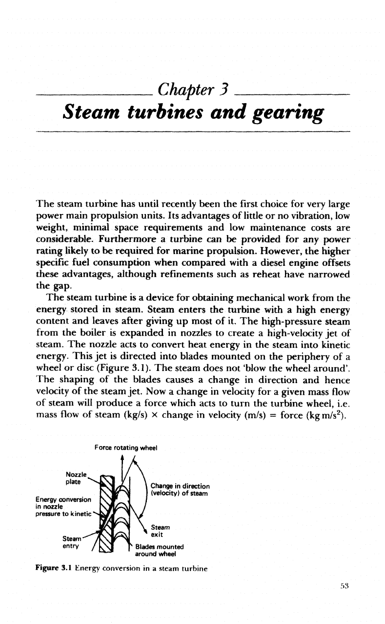
The
nozzle acts
to
convert heat energy
in the
steam into kinetic
energy. This
jet is
directed into blades mounted
on the
periphery
of a
wheel
or
disc (Figure
3.1).
The
steam
does
not
'blow
the
wheel
around'.
The
shaping
of the
blades causes
a
change
in
direction
and
hence
velocity
of the
steam jet.
Now a
change
in
velocity
for a
given
mass
flow
of
steam
will
produce
a
force
which
acts
to
turn
the
turbine wheel, i.e.
mass
flow
of
steam
(kg/s)
x
change
in
velocity
(m/s)
=
force
(kgm/s
2
).
Force
rotating
wheel
Nozzle
plate
*"
Energy
conversion
in
nozzle
pressure
to
kinetic
Steam
entry
Change
in
direction
(velocity)
of
steam
Blades
mounted
around wheel
Figure
3.1
Energy
conversion
in a
steam
turbine
Chapter
3
Steam
turbines
and
gearing
54
Steam
turbines
and
gearing
This
is the
operating
principle
of all
steam turbines, although
the
arrangements
may
vary
considerably.
The
steam
from
the first set of
blades then passes
to
another
set of
nozzles
and
then blades
and so on
along
the
rotor
shaft until
it is finally
exhausted. Each
set
comprising
nozzle
and
blades
is
called
a
stage.
Turbine types
There
are two
main types
of
turbine,
the
'impulse'
and the
'reaction'.
The
names refer
to the
type
of
force
which
acts
on the
blades
to
turn
the
turbine wheel.
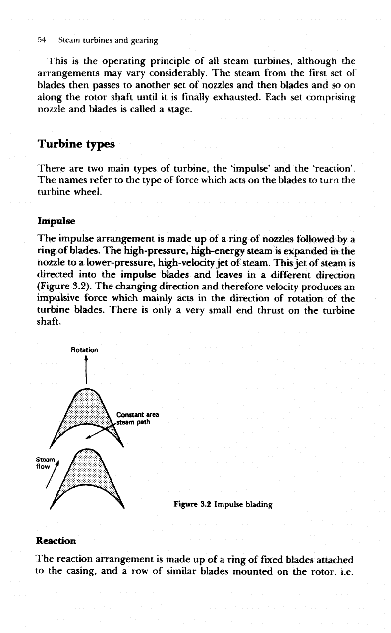
Impulse
The
impulse arrangement
is
made
up of a
ring
of
nozzles followed
by a
ring
of
blades.
The
high-pressure,
high-energy
steam
is
expanded
in the
nozzle
to a
lower-pressure,
high-velocity
jet of
steam.
This
jet of
steam
is
directed
into
the
impulse blades
and
leaves
in a
different direction
(Figure 3.2).
The
changing direction
and
therefore velocity
produces
an
impulsive force which mainly acts
in the
direction
of
rotation
of the
turbine blades.
There
is
only
a
very
small
end
thrust
on the
turbine
shaft.
Rotation
Constant
area
steam
path
Figure
3,2
Impulse
blading
Reaction
The
reaction arrangement
is
made
up of a ring of fixed
blades attached
to the
casing,
and a row of
similar blades mounted
on the
rotor,
i.e.
Steam
turbines
and
gearing
55
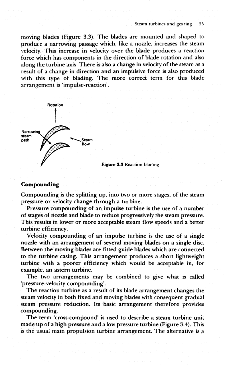
moving
blades (Figure 3.3).
The
blades
are
mounted
and
shaped
to
produce
a
narrowing passage
which,
like
a
nozzle,
increases
the
steam
velocity.
This increase
in
velocity
over
the
blade produces
a
reaction
force
which
has
components
in the
direction
of
blade
rotation
and
also
along
the
turbine
axis.
There
is
also
a
change
in
velocity
of the
steam
as a
result
of a
change
in
direction
and an
impulsive force
is
also produced
with
this
type
of
blading.
The
more correct term
for
this
blade
arrangement
is
'impulse-reaction'.
Rotation
Narrowing
steam
path
/JC
^""--*
Steam
flow
Figure
3.3
Reaction
blading
Compounding
Compounding
is the
splitting
up,
into
two or
more stages,
of the
steam
pressure
or
velocity change through
a
turbine.
Pressure
compounding
of an
impulse turbine
is the use of a
number
of
stages
of
nozzle
and
blade
to
reduce
progressively
the
steam pressure.
This results
in
lower
or
more acceptable steam
flow
speeds
and a
better
turbine
efficiency.
Velocity
compounding
of an
impulse turbine
is the use of a
single
nozzle
with
an
arrangement
of
several moving blades
on a
single disc.
Between
the
moving blades
are fitted
guide blades which
are
connected
to
the
turbine casing. This arrangement produces
a
short lightweight
turbine
with
a
poorer
efficiency
which
would
be
acceptable
in, for
example,
an
astern turbine.
The two
arrangements
may be
combined
to
give what
is
called
'pressure-velocity
compounding'.
The
reaction turbine
as a
result
of its
blade arrangement changes
the
steam velocity
in
both
fixed and
moving blades
with
consequent gradual
steam
pressure
reduction.
Its
basic arrangement therefore provides
compounding.
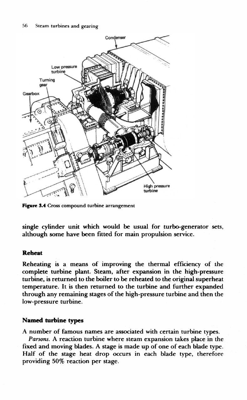
The
term
'cross-compound'
is
used
to
describe
a
steam turbine unit
made
up of a
high pressure
and a low
pressure turbine (Figure 3.4). This
is
the
usual
main
propulsion turbine arrangement.
The
alternative
is a
56
Steam
turbines
and
gearing
Low
pressure
turbine
Turning
gear
Gearbox
High pressure
turbine
Figure
3.4
Cross
compound
turbine
arrangement
single
cylinder unit
which
would
be
usual
for
turbo-generator sets,
although some
have
been
fitted for
main propulsion service.
Reheat
Reheating
is a
means
of
improving
the
thermal
efficiency
of the
complete turbine plant. Steam,
after
expansion
in the
high-pressure
turbine,
is
returned
to the
boiler
to be
reheated
to the
original
superheat
temperature.
It is
then
returned
to the
turbine
and
further expanded
through
any
remaining stages
of the
high-pressure turbine
and
then
the
low-pressure
turbine.
Named
turbine
types
A
number
of
famous
names
are
associated
with
certain turbine
types.
Parsons.
A
reaction turbine where steam expansion takes place
in the
fixed and
moving blades.
A
stage
is
made
up of one of
each blade type.
Half
of the
stage heat drop occurs
in
each blade type, therefore
providing
50%
reaction
per
stage.
Steam
turbines
and
gearing
57
Curtis.
An
impulse turbine
with
more than
one row of
blades
to
each
row
of
nozzles, i.e.
velocity
compounded.
De
Laval,
A
high-speed
impulse
turbine
which
has
only
one row of
nozzles
and one row of
blades.
Rateau.
An
impulse turbine
with
several stages, each stage being
a row
of
nozzles
and a row of
blades, i.e. pressure compounded.
Marine
steam turbines
are
required
to be
reversible. This
is
normally
achieved
by the use of
several rows
of
astern blading
fitted to the
high-pressure
and
low-pressure turbine
shafts
to
produce
astern
turbines.
About
50% of
full
power
is
achieved using these astern
turbines.
When
the
turbine
is
operating ahead
the
astern blading acts
as
an
air
compressor, resulting
in
windage
and
friction
losses.
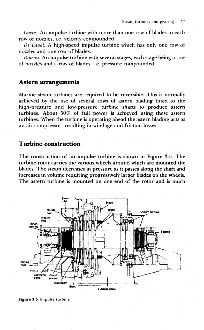
Turbine
construction
The
construction
of an
impulse turbine
is
shown
in
Figure 3.5.
The
turbine rotor carries
the
various wheels around
which
are
mounted
the
blades.
The
steam
decreases
in
pressure
as it
passes along
the
shaft
and
increases
in
volume
requiring progressively
larger
blades
on the
wheels.
The
astern turbine
is
mounted
on one end of the
rotor
and is
much
Caring
Attem
turbine
Bearing
Diaphragm
Exhauftfteam
Figure
3.5
Impulse
turbine
58
Steam
turbines
and
gearing
shorter than
the
ahead turbine.
The
turbine rotor
is
supported
by
bearings
at
either end;
one
bearing incorporates
a
thrust collar
to
resist
any
axial loading.
The
turbine casing
completely
surrounds
the
rotor
and
provides
the
inlet
and
exhaust passages
for the
steam.
At the
inlet point
a
nozzle
box
is
provided
which
by use of a
number
of
nozzle
valves
admits
varying
amounts
of
steam
to the
nozzles
in
order
to
control
the
power developed
by
the
turbine.
The first set of
nozzles
is
mounted
in a
nozzle ring
fitted
into
the
casing. Diaphragms
are
circular plates fastened
to the
easing
which
are fitted
between
the
turbine wheels. They have
a
central circular
hole
through
which
the
rotor
shaft
passes.
The
diaphragms contain
the
nozzles
for
steam expansion
and a
gland
is
fitted
between
the
rotor
and
the
diaphragm.
The
construction
of a
reaction turbine
differs
somewhat
in
that there
are no
diaphragms
fitted and
instead
Fixed
blades
are
located between
the
moving
blades.
Rotor
The
turbine rotor acts
as the
shaft
which
transmits
the
mechanical power
produced
to the
propeller
shaft
via the
gearing.
It may be a
single piece
with
the
wheels integral
with
the
shaft
or
built
up
from
a
shaft
and
separate
wheels where
the
dimensions
are
large.
The
rotor
ends adjacent
to the
turbine wheels have
an
arrangement
of
raised
rings
which
form
part
of the
labyrinth gland sealing system,
described later
in
this chapter. Journal bearings
are fitted at
each
end of
the
rotor.
These
have
rings
arranged
to
stop
oil
travelling along
the
shaft
which
would
mix
with
the
steam.
One end of the
rotor
has a
small thrust
collar
for
correct longitudinal alignment.
The
other
end has an
appropriate
flange
or fitting
arranged
for the flexible
coupling which
joins
the
rotor
to the
gearbox pinion.
The
blades
are fitted
into grooves
of
various designs
cut
into
the
wheels.
Blades
The
shaping
and
types
of
turbine
blades
have already been discussed.
When
the
turbine
rotor
is
rotating
at
high
speed
the
blades
will
be
subjected
to
considerable centrifugal force
and
variations
in
steam
velocity
across
the
blades
will
result
in
blade vibration.
Expansion
and
contraction
will
also occur during turbine operation,
therefore
a
means
of firmly
securing
the
blades
to the
wheel
is
essential.
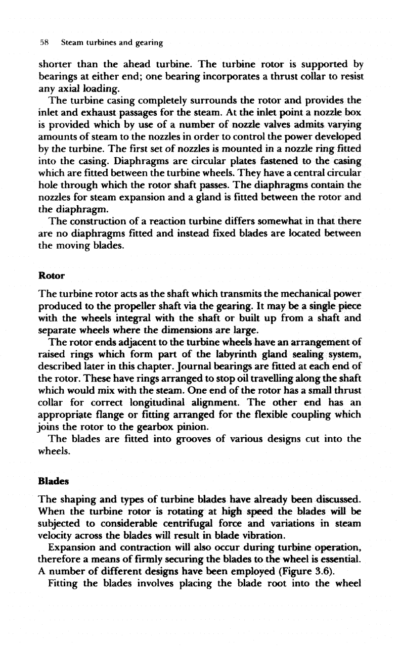
A
number
of
different
designs
have been employed (Figure 3.6).
Fitting
the
blades
involves
placing
the
blade root into
the
wheel
Steam
turbines
and
gearing
59
Multi
fork
Figure
3,6
Blade
fastening
T-slot
Fir
tree
through
a
gate
or
entrance slot
and
sliding
it
into position. Successive
blades
are
fitted
in
turn
and the
gate
finally
closed
with
a
packing piece
which
is
pinned into place. Shrouding
is
then
fitted
over tenons
on the
upper edge
of the
blades.
Alternatively,
lacing
wires
may be
passed
through
and
brazed
to all the
blades.
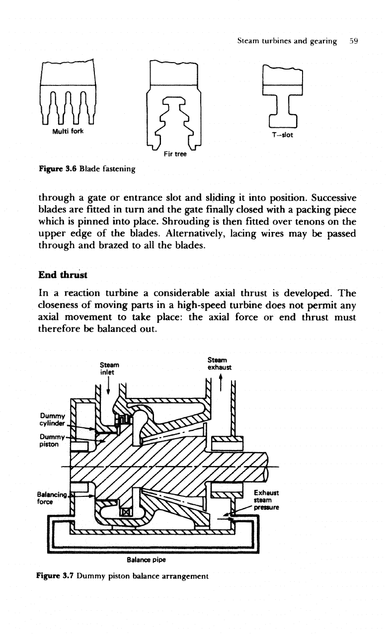
End
thrust
In
a
reaction turbine
a
considerable axial thrust
is
developed.
The
closeness
of
moving parts
in a
high-speed turbine does
not
permit
any
axial
movement
to
take place:
the
axial force
or end
thrust must
therefore
be
balanced out.
Dummy
cylinder
Dummy
piston
Balancing
force
Balance
pipe
Figure
3.7
Dummy piston
balance
arrangement