Sommerville I. Software Engineering (9th edition)
Подождите немного. Документ загружается.

44 Chapter 2 ■ Software processes
Change adds to the costs of software development because it usually means that
work that has been completed has to be redone. This is called rework. For example, if
the relationships between the requirements in a system have been analyzed and new
requirements are then identified, some or all of the requirements analysis has to be
repeated. It may then be necessary to redesign the system to deliver the new require-
ments, change any programs that have been developed, and re-test the system.
There are two related approaches that may be used to reduce the costs of rework:
1. Change avoidance, where the software process includes activities that can antic-
ipate possible changes before significant rework is required. For example, a pro-
totype system may be developed to show some key features of the system to
customers. They can experiment with the prototype and refine their require-
ments before committing to high software production costs.
2. Change tolerance, where the process is designed so that changes can be accom-
modated at relatively low cost. This normally involves some form of incremen-
tal development. Proposed changes may be implemented in increments that
have not yet been developed. If this is impossible, then only a single increment
(a small part of the system) may have to be altered to incorporate the change.
In this section, I discuss two ways of coping with change and changing system
requirements. These are:
1. System prototyping, where a version of the system or part of the system is developed
quickly to check the customer’s requirements and the feasibility of some design
decisions. This supports change avoidance as it allows users to experiment with the
system before delivery and so refine their requirements. The number of require-
ments change proposals made after delivery is therefore likely to be reduced.
2. Incremental delivery, where system increments are delivered to the customer for
comment and experimentation. This supports both change avoidance and
change tolerance. It avoids the premature commitment to requirements for the
whole system and allows changes to be incorporated into later increments at rel-
atively low cost.
The notion of refactoring, namely improving the structure and organization of a
program, is also an important mechanism that supports change tolerance. I discuss
this in Chapter 3, which covers agile methods.
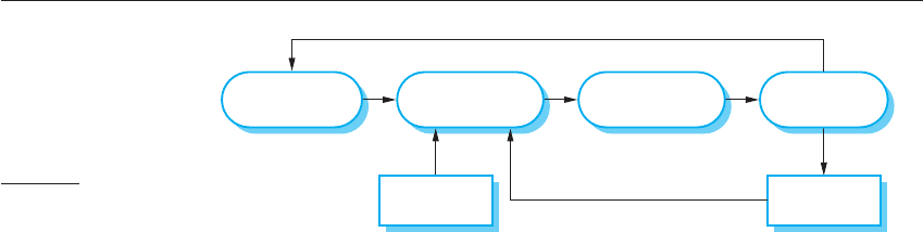
Assess Existing
Systems
Define System
Requirements
Propose System
Changes
Modify
Systems
New
System
Existing
Systems
Figure 2.8 System
evolution
2.3 ■ Coping with change 45
2.3.1 Prototyping
A prototype is an initial version of a software system that is used to demonstrate
concepts, try out design options, and find out more about the problem and its possi-
ble solutions. Rapid, iterative development of the prototype is essential so that costs
are controlled and system stakeholders can experiment with the prototype early in
the software process.
A software prototype can be used in a software development process to help
anticipate changes that may be required:
1. In the requirements engineering process, a prototype can help with the elicita-
tion and validation of system requirements.
2. In the system design process, a prototype can be used to explore particular soft-
ware solutions and to support user interface design.
System prototypes allow users to see how well the system supports their work.
They may get new ideas for requirements, and find areas of strength and weakness in
the software. They may then propose new system requirements. Furthermore, as the
prototype is developed, it may reveal errors and omissions in the requirements that
have been proposed. A function described in a specification may seem useful and well
defined. However, when that function is combined with other functions, users often
find that their initial view was incorrect or incomplete. The system specification may
then be modified to reflect their changed understanding of the requirements.
A system prototype may be used while the system is being designed to carry out
design experiments to check the feasibility of a proposed design. For example, a
database design may be prototyped and tested to check that it supports efficient data
access for the most common user queries. Prototyping is also an essential part of the
user interface design process. Because of the dynamic nature of user interfaces, tex-
tual descriptions and diagrams are not good enough for expressing the user interface
requirements. Therefore, rapid prototyping with end-user involvement is the only
sensible way to develop graphical user interfaces for software systems.
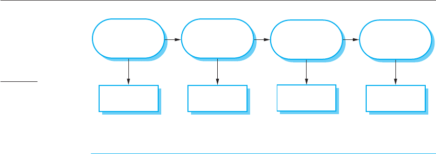
A process model for prototype development is shown in Figure 2.9. The objec-
tives of prototyping should be made explicit from the start of the process. These may
be to develop a system to prototype the user interface, to develop a system to validate
functional system requirements, or to develop a system to demonstrate the feasibility
Establish
Prototype
Objectives
Define
Prototype
Functionality
Develop
Prototype
Evaluate
Prototype
Prototyping
Plan
Outline
Definition
Executable
Prototype
Evaluation
Report
Figure 2.9 The process
of prototype
development

46 Chapter 2 ■ Software processes
of the application to managers. The same prototype cannot meet all objectives. If the
objectives are left unstated, management or end-users may misunderstand the func-
tion of the prototype. Consequently, they may not get the benefits that they expected
from the prototype development.
The next stage in the process is to decide what to put into and, perhaps more
importantly, what to leave out of the prototype system. To reduce prototyping costs
and accelerate the delivery schedule, you may leave some functionality out of the
prototype. You may decide to relax non-functional requirements such as response
time and memory utilization. Error handling and management may be ignored unless
the objective of the prototype is to establish a user interface. Standards of reliability
and program quality may be reduced.
The final stage of the process is prototype evaluation. Provision must be made
during this stage for user training and the prototype objectives should be used to
derive a plan for evaluation. Users need time to become comfortable with a new sys-
tem and to settle into a normal pattern of usage. Once they are using the system nor-
mally, they then discover requirements errors and omissions.
A general problem with prototyping is that the prototype may not necessarily be
used in the same way as the final system. The tester of the prototype may not be typ-
ical of system users. The training time during prototype evaluation may be insuffi-
cient. If the prototype is slow, the evaluators may adjust their way of working and
avoid those system features that have slow response times. When provided with bet-
ter response in the final system, they may use it in a different way.
Developers are sometimes pressured by managers to deliver throwaway proto-
types, particularly when there are delays in delivering the final version of the soft-
ware. However, this is usually unwise:
1. It may be impossible to tune the prototype to meet non-functional requirements,
such as performance, security, robustness, and reliability requirements, which
were ignored during prototype development.
2. Rapid change during development inevitably means that the prototype is undoc-
umented. The only design specification is the prototype code. This is not good
enough for long-term maintenance.
3. The changes made during prototype development will probably have degraded
the system structure. The system will be difficult and expensive to maintain.
4. Organizational quality standards are normally relaxed for prototype development.
Prototypes do not have to be executable to be useful. Paper-based mock-ups of
the system user interface (Rettig, 1994) can be effective in helping users refine an
interface design and work through usage scenarios. These are very cheap to develop
and can be constructed in a few days. An extension of this technique is a Wizard of
Oz prototype where only the user interface is developed. Users interact with this
interface but their requests are passed to a person who interprets them and outputs
the appropriate response.
2.3 ■ Coping with change 47
2.3.2 Incremental delivery
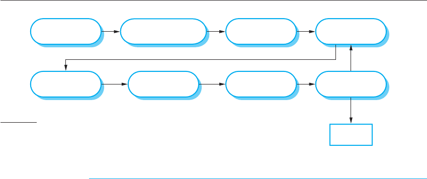
Incremental delivery (Figure 2.10) is an approach to software development where
some of the developed increments are delivered to the customer and deployed for use
in an operational environment. In an incremental delivery process, customers iden-
tify, in outline, the services to be provided by the system. They identify which of the
services are most important and which are least important to them. A number of
delivery increments are then defined, with each increment providing a sub-set of the
system functionality. The allocation of services to increments depends on the service
priority, with the highest-priority services implemented and delivered first.
Once the system increments have been identified, the requirements for the serv-
ices to be delivered in the first increment are defined in detail and that increment is
developed. During development, further requirements analysis for later increments
can take place but requirements changes for the current increment are not accepted.
Once an increment is completed and delivered, customers can put it into service.
This means that they take early delivery of part of the system functionality. They can
experiment with the system and this helps them clarify their requirements for later sys-
tem increments. As new increments are completed, they are integrated with existing
increments so that the system functionality improves with each delivered increment.
Incremental delivery has a number of advantages:
1. Customers can use the early increments as prototypes and gain experience that
informs their requirements for later system increments. Unlike prototypes, these
are part of the real system so there is no re-learning when the complete system is
available.
2. Customers do not have to wait until the entire system is delivered before they
can gain value from it. The first increment satisfies their most critical require-
ments so they can use the software immediately.
3. The process maintains the benefits of incremental development in that it should
be relatively easy to incorporate changes into the system.
4. As the highest-priority services are delivered first and increments then inte-
grated, the most important system services receive the most testing. This means
Design System
Architecture
Define Outline
Requirements
Assign Requirements
to Increments
System
Incomplete?
Final
System
Develop System
Increment
Validate
Increment
Integrate
Increment
Validate
System
Deploy
Increment
System
Complete?
Figure 2.10 Incremental
delivery

48 Chapter 2 ■ Software processes
that customers are less likely to encounter software failures in the most impor-
tant parts of the system.
However, there are problems with incremental delivery:
1. Most systems require a set of basic facilities that are used by different parts of the
system. As requirements are not defined in detail until an increment is to be
implemented, it can be hard to identify common facilities that are needed by all
increments.
2. Iterative development can also be difficult when a replacement system is being
developed. Users want all of the functionality of the old system and are often
unwilling to experiment with an incomplete new system. Therefore, getting use-
ful customer feedback is difficult.
3. The essence of iterative processes is that the specification is developed in conjunc-
tion with the software. However, this conflicts with the procurement model of
many organizations, where the complete system specification is part of the system
development contract. In the incremental approach, there is no complete system
specification until the final increment is specified. This requires a new form of
contract, which large customers such as government agencies may find difficult to
accommodate.
There are some types of system where incremental development and delivery is
not the best approach. These are very large systems where development may involve
teams working in different locations, some embedded systems where the software
depends on hardware development and some critical systems where all the require-
ments must be analyzed to check for interactions that may compromise the safety or
security of the system.
These systems, of course, suffer from the same problems of uncertain and chang-
ing requirements. Therefore, to address these problems and get some of the benefits
of incremental development, a process may be used in which a system prototype is
developed iteratively and used as a platform for experiments with the system
requirements and design. With the experience gained from the prototype, definitive
requirements can then be agreed.
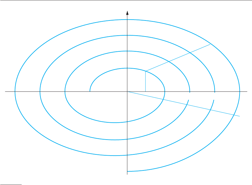
2.3.3 Boehm’s spiral model
A risk-driven software process framework (the spiral model) was proposed by
Boehm (1988). This is shown in Figure 2.11. Here, the software process is repre-
sented as a spiral, rather than a sequence of activities with some backtracking from
one activity to another. Each loop in the spiral represents a phase of the software
process. Thus, the innermost loop might be concerned with system feasibility, the
next loop with requirements definition, the next loop with system design, and so on.
The spiral model combines change avoidance with change tolerance. It assumes that
2.3 ■ Coping with change 49
changes are a result of project risks and includes explicit risk management activities
to reduce these risks.
Each loop in the spiral is split into four sectors:
1. Objective setting Specific objectives for that phase of the project are defined.
Constraints on the process and the product are identified and a detailed manage-
ment plan is drawn up. Project risks are identified. Alternative strategies,
depending on these risks, may be planned.
2. Risk assessment and reduction For each of the identified project risks, a detailed
analysis is carried out. Steps are taken to reduce the risk. For example, if there is a
risk that the requirements are inappropriate, a prototype system may be developed.
3. Development and validation After risk evaluation, a development model for the
system is chosen. For example, throwaway prototyping may be the best devel-
opment approach if user interface risks are dominant. If safety risks are the main
consideration, development based on formal transformations may be the most
appropriate process, and so on. If the main identified risk is sub-system integra-
tion, the waterfall model may be the best development model to use.
4. Planning The project is reviewed and a decision made whether to continue with
a further loop of the spiral. If it is decided to continue, plans are drawn up for the
next phase of the project.
Figure 2.11 Boehm’s
spiral model of the
software process
(©IEEE 1988)
Risk
Analysis
Risk
Analysis
Risk
Analysis
Risk
Analysis
Proto-
type 1
Prototype 2
Prototype 3
Operational
Prototype
Concept of
Operation
S/W
Requirements
Requirement
Validation
Design
V&V
Product
Design
Detailed
Design
Code
Unit Test
Integration
Test
Acceptance
Test
Service
Develop, Verify
Next-Level Product
Evaluate Alternatives,
Identify, Resolve Risks
Determine Objectives,
Alternatives, and
Constraints
Plan Next Phase
Integration
and Test Plan
Development
Plan
Requirements Plan
Life-Cycle Plan
REVIEW
Simulations, Models, Benchmarks

50 Chapter 2 ■ Software processes
The main difference between the spiral model and other software process models is
its explicit recognition of risk. A cycle of the spiral begins by elaborating objectives
such as performance and functionality. Alternative ways of achieving these objec-
tives, and dealing with the constraints on each of them, are then enumerated. Each
alternative is assessed against each objective and sources of project risk are identi-
fied. The next step is to resolve these risks by information-gathering activities such
as more detailed analysis, prototyping, and simulation.
Once risks have been assessed, some development is carried out, followed by a plan-
ning activity for the next phase of the process. Informally, risk simply means something
that can go wrong. For example, if the intention is to use a new programming language,
a risk is that the available compilers are unreliable or do not produce sufficiently effi-
cient object code. Risks lead to proposed software changes and project problems such as
schedule and cost overrun, so risk minimization is a very important project management
activity. Risk management, an essential part of project management, is covered in
Chapter 22.
2.4 The Rational Unified Process
The Rational Unified Process (RUP) (Krutchen, 2003) is an example of a modern
process model that has been derived from work on the UML and the associated Unified
Software Development Process (Rumbaugh, et al., 1999; Arlow and Neustadt, 2005).
I have included a description here, as it is a good example of a hybrid process model.
It brings together elements from all of the generic process models (Section 2.1), illus-
trates good practice in specification and design (Section 2.2) and supports prototyping
and incremental delivery (Section 2.3).
The RUP recognizes that conventional process models present a single view of
the process. In contrast, the RUP is normally described from three perspectives:
1. A dynamic perspective, which shows the phases of the model over time.
2. A static perspective, which shows the process activities that are enacted.
3. A practice perspective, which suggests good practices to be used during the process.
Most descriptions of the RUP attempt to combine the static and dynamic perspec-
tives in a single diagram (Krutchen, 2003). I think that makes the process harder to
understand, so I use separate descriptions of each of these perspectives.
The RUP is a phased model that identifies four discrete phases in the software
process. However, unlike the waterfall model where phases are equated with process
activities, the phases in the RUP are more closely related to business rather than
technical concerns. Figure 2.11 shows the phases in the RUP. These are:
1. Inception The goal of the inception phase is to establish a business case for the
system. You should identify all external entities (people and systems) that will
2.4 ■ The Rational Unified Process 51
interact with the system and define these interactions. You then use this infor-
mation to assess the contribution that the system makes to the business. If this
contribution is minor, then the project may be cancelled after this phase.
2. Elaboration The goals of the elaboration phase are to develop an understanding
of the problem domain, establish an architectural framework for the system,
develop the project plan, and identify key project risks. On completion of this
phase you should have a requirements model for the system, which may be a set
of UML use-cases, an architectural description, and a development plan for the
software.
3. Construction The construction phase involves system design, programming, and
testing. Parts of the system are developed in parallel and integrated during this
phase. On completion of this phase, you should have a working software system
and associated documentation that is ready for delivery to users.
4. Transition The final phase of the RUP is concerned with moving the system
from the development community to the user community and making it work in
a real environment. This is something that is ignored in most software process
models but is, in fact, an expensive and sometimes problematic activity. On
completion of this phase, you should have a documented software system that is
working correctly in its operational environment.
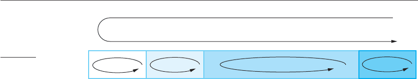
Iteration within the RUP is supported in two ways. Each phase may be enacted in
an iterative way with the results developed incrementally. In addition, the whole set
of phases may also be enacted incrementally, as shown by the looping arrow from
Transition to Inception in Figure 2.12.
The static view of the RUP focuses on the activities that take place during the
development process. These are called workflows in the RUP description. There are
six core process workflows identified in the process and three core supporting work-
flows. The RUP has been designed in conjunction with the UML, so the workflow
description is oriented around associated UML models such as sequence models,
object models, etc. The core engineering and support workflows are described in
Figure 2.13.
The advantage in presenting dynamic and static views is that phases of the devel-
opment process are not associated with specific workflows. In principle at least, all
of the RUP workflows may be active at all stages of the process. In the early phases
of the process, most effort will probably be spent on workflows such as business
modelling and requirements and, in the later phases, in testing and deployment.
Inception Elaboration Construction
Phase Iteration
Transition
Figure 2.12 Phases in
the Rational Unified
Process
52 Chapter 2 ■ Software processes
The practice perspective on the RUP describes good software engineering prac-
tices that are recommended for use in systems development. Six fundamental best
practices are recommended:
1. Develop software iteratively Plan increments of the system based on customer
priorities and develop the highest-priority system features early in the develop-
ment process.
2. Manage requirements Explicitly document the customer’s requirements and
keep track of changes to these requirements. Analyze the impact of changes on
the system before accepting them.
3. Use component-based architectures Structure the system architecture into com-
ponents, as discussed earlier in this chapter.
4. Visually model software Use graphical UML models to present static and
dynamic views of the software.
5. Verify software quality Ensure that the software meets the organizational quality
standards.
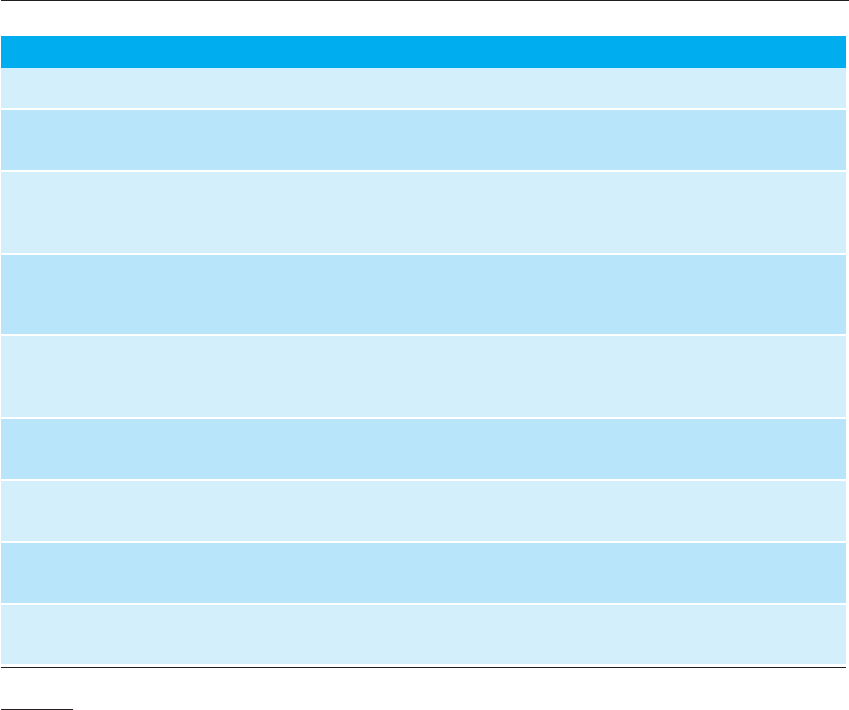
Figure 2.13 Static
workflows in the
Rational Unified
Process
Workflow Description
Business modelling The business processes are modelled using business use cases.
Requirements Actors who interact with the system are identified and use
cases are developed to model the system requirements.
Analysis and design A design model is created and documented using architectural
models, component models, object models, and sequence
models.
Implementation The components in the system are implemented and
structured into implementation sub-systems. Automatic code
generation from design models helps accelerate this process.
Testing Testing is an iterative process that is carried out in conjunction
with implementation. System testing follows the completion of
the implementation.
Deployment A product release is created, distributed to users, and installed
in their workplace.
Configuration and change management This supporting workflow manages changes to the system (see
Chapter 25).
Project management This supporting workflow manages the system development
(see Chapters 22 and 23).
Environment This workflow is concerned with making appropriate software
tools available to the software development team.

Chapter 2 ■ Key points 53
K E Y P O I N T S
■ Software processes are the activities involved in producing a software system. Software process
models are abstract representations of these processes.
■ General process models describe the organization of software processes. Examples of these general
models include the waterfall model, incremental development, and reuse-oriented development.
■ Requirements engineering is the process of developing a software specification. Specifications
are intended to communicate the system needs of the customer to the system developers.
■ Design and implementation processes are concerned with transforming a requirements
specification into an executable software system. Systematic design methods may be used as
part of this transformation.
■ Software validation is the process of checking that the system conforms to its specification and
that it meets the real needs of the users of the system.
■ Software evolution takes place when you change existing software systems to meet new
requirements. Changes are continuous and the software must evolve to remain useful.
■ Processes should include activities to cope with change. This may involve a prototyping phase
that helps avoid poor decisions on requirements and design. Processes may be structured for
iterative development and delivery so that changes may be made without disrupting the system
as a whole.
■ The Rational Unified Process is a modern generic process model that is organized into phases
(inception, elaboration, construction, and transition) but separates activities (requirements,
analysis, and design, etc.) from these phases.
6. Control changes to software Manage changes to the software using a change
management system and configuration management procedures and tools.
The RUP is not a suitable process for all types of development, e.g., embedded
software development. However, it does represent an approach that potentially com-
bines the three generic process models discussed in Section 2.1. The most important
innovations in the RUP are the separation of phases and workflows, and the recogni-
tion that deploying software in a user’s environment is part of the process. Phases are
dynamic and have goals. Workflows are static and are technical activities that are not
associated with a single phase but may be used throughout the development to
achieve the goals of each phase.