Schweitzer P.A. Fundamentals of corrosion. Mechanisms, causes, and preventative methods
Подождите немного. Документ загружается.

Corrosion of Metallic Coatings 259
ηη η=+
ac
The activation overpotential·η
w
results from the potential energy barrier
to overcome for a charge to cross the electrical double layer at the interface (
that Is, M ↔ M
n+
+ ne
−
) and is given as follows:
In the anodic reaction,
ηβ
a
a
a
= log
i
i
a
oa
β
a
RT
nF
=
∝
23.
Log Current Density
i
corr.
i
L
i
oa
i
oc
E
a
E
corr.
Concentration
overpotential
Activation
overpotential
Activation
overpotential
M
M
n+
+ ne
Electrode Potential
E
corr.
E
c
O
2
+ 2H
2
O + 4e
4OH
–
η
c
α
η
a
a
η
c
c
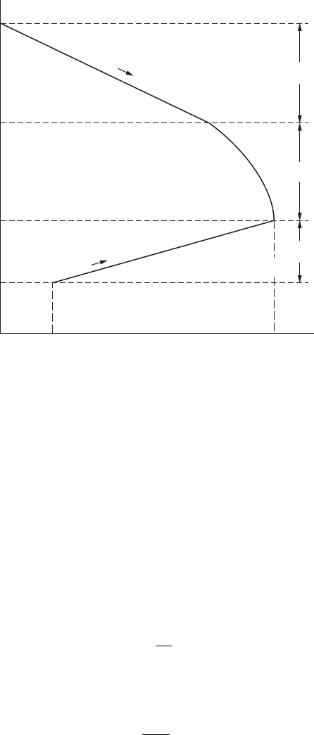
FigurE 8.3
Activation and. concentration overpotentials in a typical corrosion process.

260 Fundamentals of Corrosion
In the cathodic reaction,
ηβ
c
a
c
= log
i
i
c
oc
β
c
=
−∝
()
23
1
i RT
nF
where
η
a
a
and
η
c
a
are the activation overpotentials in the anodic and cathodic
reactions, β
a
and β
c
are the anodic and cathodic Tafel coefcients,
∝
is the
transfer coefcient, i
a
and i
c
are the anodic and cathodic current densities,
and i
oa
and i
oc
are the exchange current densities of the anodes and cathodes,
respectively. The energy transfer factor,
∝
, indicates the degree of contribu-
tion of electrical energy for the activation energy in the electrode reaction
01<∝<
()
. In most cases,
∝
is 0.3 to 0.7. The exchange current density, i
oa
or i
oc
, is the ux of charge that passes through the electrical double layer at
the single-equilibrium potential, E
a
or E
c
. Other factors have been mentioned
already. There is a linear relationship between η
a
and log i
a
or i
c
. Tafel coef-
cient β
a
or β
c
is the slope, dη
a
/d(log i
a
or i
c
), of the polarization curve, so that
β is one of the important factors that control the corrosion rate.
Generally, activation overpotential controls the electrode reaction at the
low reaction rate. The cathodic reaction 2H
+
+ 2e
−
→ H
2
is, in the acid solu-
tion, one of the processes controlled by the activation overpotential. Table 8.2
shows hydrogen overpotentials of various metals. The activation overpo-
tential varies with the kind of metal and the electrolytic condition. In most
cases, metal dissolution and metal-ion deposition are controlled by the acti-
vation overpotential.
Therefore, the anodic overpotential η
a
is usually given by:
ηβ
aa
= log
i
i
a
oa
On the other hand, the concentration overpotential becomes the control-
ling factor in the electrode reaction at high reaction rate; in this case the elec-
trode reaction is controlled by the mass transfer process, that is, the diffusion
rate of reactive species. According to the diffusion layer concept, the diffu-
sion current is given as:
i
nFDC–C
o
=
()
δ
(8.1)

Corrosion of Metallic Coatings 261
where i is the current density, D is the diffusion coefcient, C is the con-
centration of reactive species in the bulk solution, C
o
is the concentration of
the reactive species at the interface, and δ is the thickness of diffusion layer.
When the concentration of reactive species at the interface is zero (C
o
= 0),
the current density shows some critical values, i
L
(called the limiting current
density); that is,
i
nFDC
L
=
δ
(8.2)
From Equations 8.1 and 8.2,
C
C
i
i
o
L
=−1
(8.3)
while the concentration overpotential η
c
is given as:
η
c
=
23.log
RT
nF
C
C
O
(8.4)
From Equations 8.3 and 8.4,
TabLE 8.2
Hydrogen Overpotentials of Various Metals
Metal
Temperature
(°C) Solution
Hydrogen
Overpotential
η
c
V/mA/cm
2
()
Tafel
Coefcient
β
c
V
()
Exchange
Current
Density
iA/cm
oc
2
()
Pt (smooth) 20 1 N HCl 0.00 0.03 10
−3
Mo 20 1 N HCl 0.12 0.04 10
−6
Au 20 1 N HCl 0.15 0.05 10
−6
Ag 20 0.1 N HCl 0.30 0.09 5 × 10
−7
Ni 20 0.1 N HCl 0.31 0.10 8 × 10
−7
Bi 20 1 N HCl 0.40 0.10 10
−7
Fe 16 1 N HCl 0.45 0.15 10
–6
Cu 20 0.1 N HCl 0.44 0.12 2 × 10
−7
Al 20 2 N H
2
SO
4
0.70 0.10 10
−10
Sn 20 1 N HCl 0.75 0.15 10
–8
Cd 16 1 N HCl 0.80 0.20 10
−7
Zn 20 1 N H
3
SO
4
0.94 0.12 1.6 × 10
−11
Pb 20 0.01–8 N HCl 1.16 0.12 2 × 10
−13

262 Fundamentals of Corrosion
η
c
=−
23
1
.
log
RT
nF
i
i
L
(8.5)
Equation 8.5 shows that the concentration overpotential increases rapidly as
i approaches i
L
, as shown in Figure 8.3.
In general, the cathodic reaction is controlled by the activation overpoten-
tial
η
c
a
and the concentration overpotential
η
c
c
. The cathodic overpotential is
ηηη
CC
q
C
C
=+
(8.6)
Therefore, from Equations 8.4 and 8.5 the cathodic overpotential is written
in the general form:
ηβ
CC
=+ −
log
.
log
i
i
RT
nF
i
i
C
OC
C
CL
23
1
(8.7)
In most cases, the importance of anodic and cathodic overpotentials is
to determine the corrosion rate. That is, the rate-determining process is
determined by the slopes of two polarization curves. Figure 8.3 shows the
schematic illustration of activation and concentration overpotentials in the
typical corrosion process.
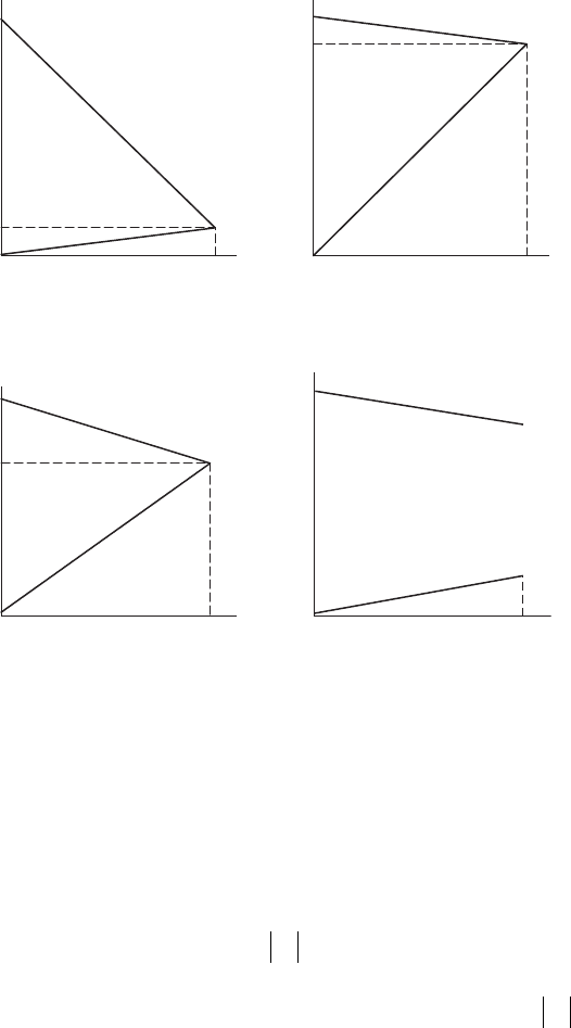
Corrosion control processes are classied into four types by the patterns of
anodic and cathodic polarization curves: anodic, mixed, cathodic, and resis-
tance controls, as shown in Figure 8.4.
The role of a coating is to isolate the substrate from the atmosphere. The iso-
lating action is based on two characteristics of coating materials: (1) the cor-
rosion resistance or the stability of coating material when coating is formed
by the defect-free continuous layer, and (2) the electrochemical action of the
coating material when the coating has some defect, such as pore and crack.
This action for a coating layer can be explained by applying the mechanism
of the corrosion cell. For better understanding, the equation
EE
Ca Ca
−= ++ηηiR
corr.
is rewritten as
I
corr.
=
−
()
−−EE
R
Ca Ca
ηη
(8.8)
although η
a
and η
c
are functions of the current.
Corrosion of Metallic Coatings 263
Therefore, a corrosion-resistant coating is achieved by considering ve surface
treatment methods to decrease i
corr
on the basis of Equation 8.8. Specically,
1. Decrease in electromotive force (E
C
– E
a
): EMF control protection
2. Increase in cathodic overpotential:
η
C
cathodic control protection
3. Increase in anodic overpotential: η
a
anodic control protection
4. Increases in both anodic and cathodic overpotential: η
a
and
η
C
,
mixed control protection
5. Increase in resistance of corrosion cell: R resistance control
protection.
Resistance Control
Log Current Density
Mixed Control
Cathodic Control
Electrode Potential
Anodic Control
i
corr
i
corr
i
corr
i
corr
E
corr
E
corr
E
corr
FigurE 8.4
Four types of corrosion controls.

264 Fundamentals of Corrosion
8.2 EMF Control Protection by Noble Metals
Noble coating metals that provide corrosion protection by means of EMF
control include copper, silver, platinum, gold, and their alloys. The standard
single potentials of these metals are more noble than those of hydrogen (refer
to Table 8.2). Therefore, the oxidizer in corrosion cells formed on these metals
in a natural environment, containing no other oxidizers, is dissolved oxygen.
Consequently, the electromotive force that causes corrosion is so small that
coating with noble metals is an effective means of providing corrosion pro-
tection. With the exception of copper, the other members of this group are
precious metals and are used primarily for electrical conduction and decora-
tive appearance.
8.2.1 Mechanism of Control Protection
8.2.1.1 Copper Coatings
Although copper is soft, it has many engineering applications in addition
to its decorative function. One such application is the corrosion protection
of steel. It can be used as an alternative to nickel to prevent fretting and
scaling corrosion. Copper can be deposited electrochemically from various
aqueous solutions. The properties of the deposit will depend on the chosen
bath and the applied procedures. The hardness of the layers varies from 40
to 160 HV.
Because copper is very noble, it causes extreme galvanically induced local
corrosion of steel and aluminum substrates. Because of this, extreme care
must be taken to produce well-adhering nonporous layers.
The corrosion protection provided by copper coating is twofold, consist-
ing of an original barrier action of the coating layer and a secondary barrier
action of corrosion products. The low EMF of copper is responsible for the
formation of the original barrier action. The electrochemical reactions in the
corrosion cell on copper are as follows:
Anodic reaction: Cu → Cu
+
+ e
−
Cu → Cu
2+
+ 2e
−
Cathodic reaction: O
2
+ H
2
O → 4e
−
+ 4OH
−
Chloride ions in a natural environment stabilize cuprous ions. Cupric ions
are more stable. Because the EMF of corrosion on copper is less than that on
iron, the reactivity of a steel surface decreases by coating it with copper.
Over a period of time, corrosion products gradually build up a secondary
layer against corrosion. Initially, a cuprous layer is formed, followed by the
copper surface covered with basic copper salts. Pollutants in the atmosphere
determine the formation of basic copper salts as follows:
Corrosion of Metallic Coatings 265
Mild atmosphere: Malachite CuCO
3
:Cu(OH)
2
SO
x
atmosphere: Brochonite CuSO
4
:3Cu(OH)
2
Chloride atmosphere: Atacamite CuCl
2
:3Cu(OH)
2
In most coastal areas, the amount of sulfates in the atmosphere exceeds
the amount of chlorides. As a layer of copper salt grows on the surface of
the corrosion product layer, the protective ability of the corrosion layer
increases. As the exposure time increases, the average corrosion rate of
copper gradually decreases. After 20 years, the corrosion rate of copper is
reduced to half the value of the rst year as a result of the secondary barrier
of corrosion products.
The initial corrosion rate of a copper coating depends on atmospheric con-
ditions such as time of wetness, and type and amount of pollutants. Time of
wetness is the most important factor affecting the corrosion rate of copper.
The corrosion rate of copper usually obeys parabolic law:
M
2
= kt
where M is the mass increase, k is a constant, and t is the exposure time.
Accordingly, the average corrosion rate decreases with increased exposure
time, which means that the surface of the copper is covered with basic salts
by degrees and thereafter the corrosion rate approaches a constant value.
Twenty-year exposure tests found the average corrosion rate of copper to
be as follows:
0.0034 mil/yr in dry rural atmospheres
0.143 mil/yr in rural atmospheres
0.0476–0.515 mil/yr in industrial atmospheres
0.0198–0.0562 mil/yr in marine atmospheres
Until the base metal is exposed, the corrosion process of a copper-coated
layer is similar to that of copper plate. Galvanic corrosion of copper-coated
steel is induced when the steel substrate is exposed. However, in the case of
copper-coated stainless steel, the occurrence of galvanic action depends on
the composition of the stainless steel.
In chloride atmospheres, galvanic pitting takes place at the pores in cop-
per layers and galvanic tunneling at cut edges on types 409 and 430 stainless
steels; whereas in SO
x
atmospheres, uniform corrosion takes place on the
copper coating.
Copper coatings are used for both decorative purposes and for corrosion
protection from the atmosphere. Copper-coated steels are used as roofs,
ashings, leaders, gutters, and architectural trim. Copper undercoat also
improves the corrosion resistance of multilayered coatings, specically in
the plating of nickel and chromium.
266 Fundamentals of Corrosion
8.2.1.2 Gold Coatings
Gold electrodeposits are primarily used to coat copper in electronic applica-
tions to protect the copper connectors and other copper components from
corrosion. It is desirable to obtain the corrosion protection with the mini-
mum thickness of gold because of the cost of the gold. As the thickness of
the electrodeposit decreases, there is a tendency for the deposit to provide
inadequate coverage of the copper. For this reason it is necessary that there
be a means whereby the coverage of the copper can be determined. Such
a test using corrosion principles as a guide has been developed. In a 0.1 M
NH
4
Cl solution, gold serves as the cathode and copper serves as the anode.
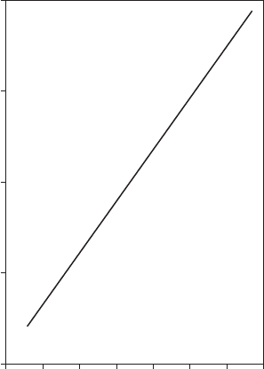
At a high cathode/anode surface area fraction, the corrosion potential is lin-
early related to the area fraction of copper exposed, as shown in Figure 8.5.
By measuring the corrosion potential of the gold-plated copper in a 0.1 M
NH
4
Cl solution, the area fraction of copper exposed is determined.
Gold coatings can also be deposited by means of electroless plating.
Borohydride or DMAB is used as the reducer with a stable gold cyanide com-
plex. Thin gold coatings can be deposited on plastics by an aerosol method
using gold complexes with amines and hydrazine as a reducer. A relatively
thick coat can be obtained.
–100–80–60–40–20
Corrosion Potential, mV (vs SCE)
Bath 0.1 M NH
4
Cl
2040
10
–7
10
–6
10
–5
Area Fraction Copper
10
–4
10
–3
0
FigurE 8.5
Data showing that the fractional exposed area of copper in a copper-gold system is linearly
related to the corrosion potential at low exposed copper areas.
Corrosion of Metallic Coatings 267
8.3 Anodic Control Protection by Noble Metals
Coating metals that provide protection by means of anodic control include
nickel, chromium, tin, lead, and their alloys.
They protect the substrate metal as a result of their resistance to corrosion
insofar as they form a well-adhering and nonporous barrier layer. However,
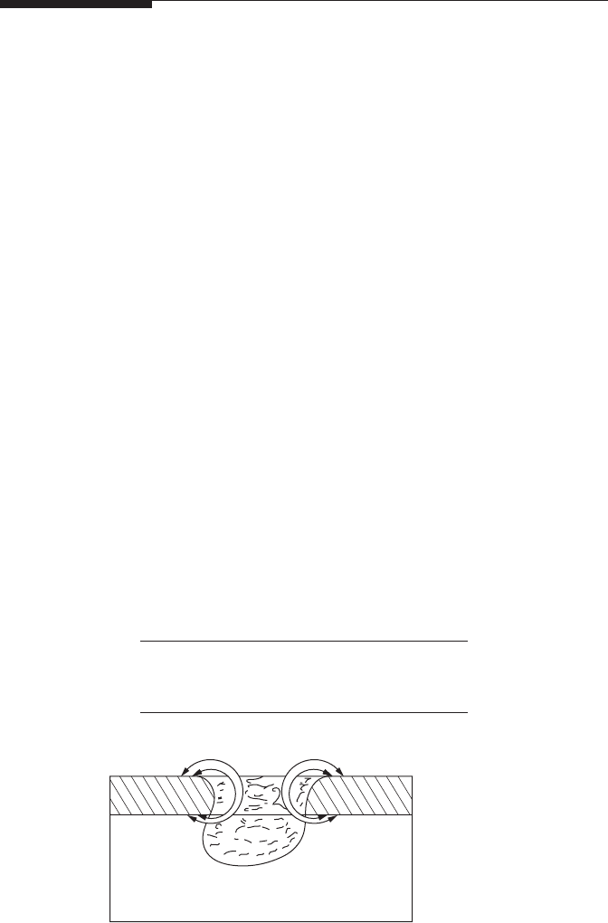
when the coating is damaged, galvanically induced corrosion will lead to
severe attack. This corrosion process is extremely fast for coated systems due
to the high current density effect as a result of the large ratio between the
surface areas and the cathodic outer surface and the anodic effect, as shown
in Figure 8.6. To compensate for these defects in the coating, multilayer
coating systems have been developed. The corrosion resistance of a single
noble layer metal coating results from the original barrier action of the noble
metal, the surface of the noble metal being passivated. With the exception of
lead, a secondary barrier of corrosion products is formed. Noble metals do
not provide cathodic protection for steel substrates because their corrosion
potential is more noble than those of iron and steel in a natural environment
(see Table 8.1). In multilayer coating systems, a small difference in potential
between coating layers results in galvanic action in coating layers.
8.3.1 Mechanisms of Control Protection
8.3.1.1 Nickel Coatings
There are three types of nickel coatings: bright, semibright, and dull bright.
The difference between the coatings is in the quantity of sulfur contained in
them, as shown:
Nickel Coating
Sulfur Content
(%)
Bright nickel deposits >0.04
Semibright nickel deposits <0.005
Dull bright nickel deposits <0.001
Substrate
e
–
e
–
Metallic film
Me
n+
FigurE 8.6
Dissolution of substrate metal in coating defect.
268 Fundamentals of Corrosion
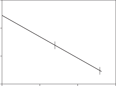
The corrosion potentials of the nickel deposits depend on the sulfur con-
tent. Figure 8.7 shows the effect of sulfur content on the corrosion potential
of a nickel deposit. A single-layer nickel coating must be greater than 30 μm
to ensure the absence of defects.
As the sulfur content increases, the corrosion potential of a nickel deposit
becomes more negative. A bright nickel coating is less protective than a semi-
bright or dull nickel coating. The difference in the potential of bright nickel
and semibright nickel deposits is more than 50 mV.
Use is made of the differences in the potential in the application of multi-
layer coatings. The more negative bright nickel deposits are used as sacri-
cial intermediate layers. When bright nickel is used as an intermediate layer,
the corrosion behavior is characterized by sideways diversion. Pitting cor-
rosion is diverted laterally when it reaches the more noble semibright nickel
deposit. Thus, the corrosion behavior of bright nickel prolongs the time for
pitting penetration to reach the base metal.
The most negative of all nickel deposits is trinickel. In this triplex layer
coating system, a coating of trinickel approximately 1 μm thick, containing
0.1 to 0.25% sulfur, is applied between bright nickel and semibright nickel
deposits. The high-sulfur nickel layer dissolves preferentially, even when pit-
ting corrosion reaches the surface of the semibright nickel deposit. Because
the high-sulfur layer reacts with the bright nickel layer, pitting corrosion
does not penetrate the high-sulfur nickel layer in the tunneling form. The
application of a high-sulfur nickel strike denitely improves the protective
ability of a multilayer nickel coating.
In the duplex nickel coating system, the thickness ratio of semibright nickel
deposit to bright nickel deposit is nominally 3:1, and a thickness of 20 to 25
Sulfur Content, wt. %
0.01 0.1 1.0
Bright nickel coating
Semibright
nickel coating
Dull
nickel
coating
0.001
Corrosion Potential of Nickel mV, SCE
–350
–400
–450
–300
FigurE 8.7
Effect of sulfur content on corrosion protection of nickel.