Rohling H. (Ed.) OFDM: Concepts for Future Communication Systems
Подождите немного. Документ загружается.

46 3 Link-Level Aspects
[33] T.Wo,C.Liu,andP.A.Hoeher,“Graph-based soft channel and data estimation
for MIMO systems with asymmetric LDPC codes,” in Proc. IEEE International
Conference on Communications (ICC), Beijing, China, May 2008, pp. 620-624.
[34] Ch. Knievel, Z. Shi, P.A. Hoeher, and G. Auer, “2D graph-based soft chan-
nel estimation for MIMO-OFDM,” in Proc. IEEE International Conference on
Communications (ICC), Capetown, South Africa, May 2010.
[35] F.R. Kschischang, B.J. Frey, and H.-A. Loeliger, “Factor graphs and the sum-
product algorithm,” IEEE Transactions on Information Theory, vol. 47, no. 2,
pp. 498-519, Feb. 2001.
[36] H.A. Loeliger, J. Dauwels, J. Hu, S. Korl, L. Ping, and F.R. Kschischang, “The
factor graph approach to model-based signal processing,” Proceedings of the
IEEE, vol. 95, no. 6, pp. 1295-1322, June 2007.
[37]T.Wo,C.Liu,andP.A.Hoeher,“Graph-based iterative Gaussian detection
with soft channel estimation for MIMO systems,” in Proc. ITG Conference on
Source and Channel Coding (SCC), Ulm, Germany, Jan. 2008.
[38] T. Wo, J.Ch. Fricke, and P.A. Hoeher, “A graph-based iterative Gaussian detec-
tor for frequency-selective MIMO channels,” in Proc. IEEE Information Theory
Workshop (ITW), Chengdu, China, Oct. 2006, pp. 581-585.
[39] H.-A. Loeliger, “An introduction to factor graphs,” IEEE Signal Processing
Magazine, vol. 21, no. 1, pp. 28-41, Jan. 2004.
3.2 Spreading 47
3.2 Spreading
J. Lindner, University of Ulm, Germany
3.2.1 Introduction
Spreading is a well known technique which can cope with the frequency-selective
behavior of common wireless transmission channels. At the transmit side no knowl-
edge of the current channel is needed. For OFDM this means that the energy of the
symbols to be transmitted is spread across subcarriers. If subcarriers are faded out
by the channel, then the receiver can still recover the symbols on the remaining un-
affected subcarriers, i.e., the frequency diversity of the channel can be exploited. In
1993 various system variants based on these ideas came up, see, e.g., [1] and also [2].
It is straightforward to apply the spreading concept to MIMO-OFDM to get access
to both, spatial and frequency diversity, while keeping the transmission rate con-
stant. For spreading there is no rate loss like in case of orthogonal space-time codes,
see, e.g., [3]. The drawback is that spreading causes mutual interference between
subcarriers and antenna signals and powerful detection methods must be used in the
receiver [4]. This project dealt with finding proper spreading schemes for MIMO-
OFDM allowing to achieve best BER performance while keeping the complexity in
limits.
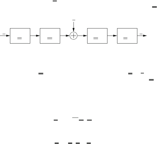
Spreading can be represented by a multiplication of the symbol vector to be trans-
mitted with a spreading matrix U. Figure 3.6 shows this as part of a vector trans-
mission model. Further blocks represent the MIMO-OFDM channel matrix H and
x
H
H
U
H
H
˜x
n
U
Figure 3.6: Block transmission model with spreading.
its matched filter matrix H
H
as well as the despreading matrix U
H
. n is a sam-
ple vector of the assumed additive white Gaussian noise vector process. H is an
(Nn
R
) × (Nn
T
) matrix containing the transfer functions of channel impulse re-
sponses between all n
T
transmit and n
R
receive antennas, and N is the number of
OFDM subcarriers [6]. The influence of the MIMO-OFDM channel including the
matched filter matrix can be described by an equivalent channel matrix (on symbol
basis)
R
MO
=
1
n
R
H
H
H. (3.15)
Spreading and despreading can be included by defining
R
S
= U
H
R
MO
U. (3.16)
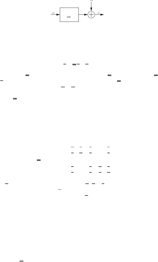
48 3 Link-Level Aspects
n
c
˜xx
R
Figure 3.7: Transmission model using the equivalent channel matrix on symbol basis.
This leads to an equivalent matrix vector transmission model which is given by
˜x = R x + n
c
. (3.17)
In the following R belongs either to the unspread case (R
MO
)orspreadcase(R
S
),
and n
c
is the colored noise vector with correlation matrix 2N
0
R. Figure 3.7 shows in
a qualitative way an example for R = R
MO
(i.e. for the unspread case). Spreading
techniques do not eliminate the interference between symbol vector components, so
in general R is not a diagonal matrix. Thus vector equalization is needed.
3.2.2 MC-CDM and MC-CAFS
For MC-CDM the symbols are spread only in frequency direction. The spreading
matrix can be described as
U
MC−CDM
=
⎛
⎜
⎜
⎜
⎜
⎜
⎜
⎜
⎝
S 0 0 ··· 0
0 S 0 ··· 0
.
.
.
.
.
.
.
.
.
.
.
.
.
.
.
0 ··· 0 S 0
0 ··· 0 0 S
⎞
⎟
⎟
⎟
⎟
⎟
⎟
⎟
⎠
, (3.18)
where S is an N × N spreading matrix with S
H
S = I,whichisrepeatedn
T
times
on the main diagonal, i.e., each S block corresponds to one transmit antenna. One
example for an orthogonal spreading matrix S is the normalized Walsh Hadamard
matrix. As can be seen in (3.18), each symbol is spread only over the subcarriers of
one transmit antenna. Therefore the maximum achievable diversity for MC-CDM
is Ln
R
,whereL denotes the number of channel taps. The scheme can easily be
adapted to any number of transmit antennas.
Multi-carrier cyclic antenna frequency spreading (MC-CAFS) defines a family of
spreading matrices that make use of the frequency as well as the spatial dimension
offered by the MIMO channel [7]. The spreading matrices spread over all transmit
antennas, and in addition, each symbol is spread over a set of subcarriers (frequen-
cies) for each transmit antenna. The frequency sets are different for each antenna.
MC-CAFS can achieve full diversity, which is n
T
n
R
L. The structure of the spread-
ing matrices U
MC−CAFS
can be found in [6] [7]. To exploit full diversity while
maintaining the orthogonality of the spreading matrix, the number of frequencies
3.2 Spreading 49
subchannel #
subchannel #
5
10
15
20
25
30
5
10
15
20
25
30
a)
5
10
15
20
25
30
0
0.2
0.4
0.6
0.8
1
1.2
1.4
1.6
subchannel #
|diag(R)|
b)
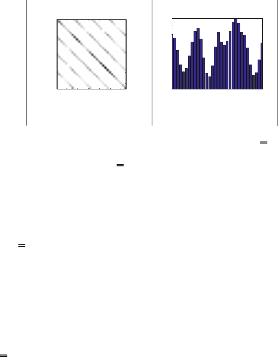
Figure 3.8: Equivalent channel matrix for unspread MIMO-OFDM. a) R
MO
for n
T
=
n
R
=4,N = 8 subcarriers, and L = 4 paths. (b) Absolute value of the
diagonal elements of R
MO
.
B, over which each symbol is spread, should fulfill the following conditions:
L ≤ B ≤ N/n
T
. (3.19)
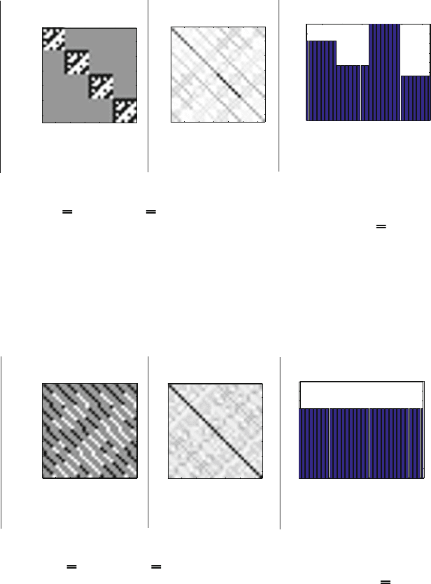
Figures 3.8 to 3.10 demonstrate the effect of spreading on the equivalent channel
matrix R for a frequency-selective time-invariant channel with L = 4 taps. Figure
3.8 is for the unspread case. Although the probability of a deep fade is reduced by
the multiple receive antennas and maximum ratio combining, the elements on the
main diagonal have a large variance. With MC-CDM spreading (see Fig. 3.9) we
can observe that the diagonal elements have the same value within each transmit
antenna block, but vary from block to block. This is due to the fact that the symbol
energy is spread over all frequencies of each antenna separately, but no spreading in
antenna direction is applied. The new scheme, i.e., MC-CAFS, includes spreading in
frequency and space direction. If the parameters of the spreading matrix are chosen
properly, it is possible to achieve constant diagonal elements on the main diagonal
of R as can be seen in Fig. 3.10. This means, the matched filter bound (MFB)
coincides with the AWGN performance.
3.2.3 Simulation Results
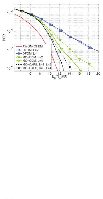
Figures 3.11 and 3.12 show a comparison of different spreading schemes for uncoded
and coded transmissions, respectively. The channel was a block fading channel
staying constant during one OFDM symbol block, but changes independently from
block to block. For equalization, a soft Cholesky equalizer (SCE) [8] was used. The
results for uncoded transmission in Fig. 3.11 show that exploiting additional diversity
by spreading improves the performance substantially compared to unspread OFDM.
MC-CAFS outperforms MC-CDM both for a channel length of L =2andL =4
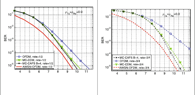
due to the additional transmit antenna diversity. Figure 3.12 shows the results
for coded transmissions using a convolutional code with memory 2 and iterative
equalization and decoding. The results for code rate 3/4 in Fig. 3.12 b) were obtained
50 3 Link-Level Aspects
subchannel #
subchannel #
5
10
15
20
25
30
5
10
15
20
25
30
a)
subchannel #
subchannel #
5
10
15
20
25
30
5
10
15
20
25
30
b)
5
10
15
20
25
30
0
0.1
0.2
0.3
0.4
0.5
0.6
0.7
0.8
0.9
1
subchannel #
|diag(R)|
c)
Figure 3.9: Equivalent channel matrix for MC-CDM: a) spreading matrix
U
MC−CDM
;b)R
MC−CDM
for n
T
= n
R
=4,N = 8 subcarriers, and
L = 4 paths; c) absolute value of the diagonal elements of R
MC−CDM
.
subchannel #
subchannel #
5
10
15
20
25
30
5
10
15
20
25
30
a)
subchannel #
subchannel #
5
10
15
20
25
30
5
10
15
20
25
30
b)
5
10
15
20
25
30
0
0.1
0.2
0.3
0.4
0.5
0.6
0.7
0.8
0.9
1
subchannel #
|diag(R)|
c)
Figure 3.10: Equivalent channel matrix for MC-CAFS: a) spreading matrix
U
MC−CAFS
;b)R
MC−CAFS
for n
T
= n
R
=4,N = 8 subcarriers, and
L = 4 paths; c) absolute value of the diagonal elements of R
MC−CAFS
.
3.2 Spreading 51
by puncturing the rate 1/2 mother code from Fig. 3.12 a). The gain obtained
through spreading increases as the code rate increases. Also the BER reduction of
MC-CAFS compared to MC-CDM is larger for code rate 3/4. These results show
that the channel code alone cannot exploit the maximum diversity even though the
symbols of the codewords are interleaved over the whole codeword, covering many
MIMO-OFDM symbols. More results and further details can be found in [6], where
also the case of precoding in the transmitter is considered.
Figure 3.11: BER for MIMO-OFDM with spreading and equalization using SCE,
4PSK, N = 32, and n
T
= n
R
=4.
3.2.4 Concluding Remarks
Spreading can help to exploit frequency as well as spatial diversity, but the spreading
scheme must be designed properly. Multi-carrier cyclic antenna frequency spreading
(MC-CAFS) can achieve excellent performance with higher transmission rates than
with channel coding only (i.e. pure COFDM), but powerful detection schemes must
be applied in the receiver, e.g., an SCE equalizer in a turbo loop with soft-in-soft-
out decoding. Compared to orthogonal space-time codes, where the rate is at most
1, the rate of MC-CAFS is – independent of the current channel – the maximum
rate, which is identical to the number n
T
of transmit antennas. If the MIMO-OFDM
channel does not have the potential for spatial multiplexing, zero or small eigenvalues
of the channel matrix R occur. As a result, the BER performance decreases, but
the transmission rate remains always constant. This is comparable to MC-CDM (or
MC-CDMA) if subchannels are faded out, because the subchannel gains of OFDM
correspond directly to the eigenvalues in case of MIMO-OFDM. Spreading is a very
general concept. This contribution is based on the work of Doris Yacoub [5–7]. More
about this topic and its relation to general space-time or space-frequency coding
and also dispersion codes can be found in [9]. The author thanks Matthias Wetz for
preparing some parts of this text.
52 3 Link-Level Aspects
E /N [dB]
b0
a) code rate 1/2
E /N [dB]
b0
b) code rate 3/4
Figure 3.12: BER of MIMO-OFDM 4PSK with convolutional code, memory 2, n
T
=
n
R
=4,N = 32, and L =4.
Bibliography
[1] K. Fazel. “Performance of CDMA/OFDM for Mobile Communication Systems,”
Proc. ICUPC ’93, pp. 975-979, 1993.
[2] J. Lindner, “MC-CDMA in the context of general multiuser/multisubchannel
transmission methods,” ETT, European Transactions on Telecommunications,
vol. 10, no. 4, pp. 351-367, 1999.
[3] V. Tarokh, H. Jafarkhani, and A.R. Calderbank, “Space-time block codes from
orthogonal designs,” IEEE Trans. Inform. Theory, vol. 45, no 5, 1999.
[4] D. Y. Yacoub, W. G. Teich, and J. Lindner, “Effect of Antenna Correlations on
Interference and Performance of a Spread MIMO-OFDM System (MC-CAFS),”
11th International OFDM-Workshop 2006, Hamburg / Germany, Aug. 2006.
[5] D. Y. Yacoub, W. G. Teich, and J. Lindner, “Precoding and Spreading for
MIMO-OFDM in the Presence of Antenna Correlations,” 12th International
OFDM-Workshop 2007, Hamburg / Germany, Aug. 2007.
[6] D.Y.Yacoub,Spreading and Coding for Wireless MIMO-OFDM Systems, Dis-
sertation, Institute for Information Technology, University of Ulm, June 2008.
[7] D. Y. Yacoub, W. G. Teich, and J. Lindner, “MC-Cyclic Antenna Frequency
Spread: A Novel Space-Frequency Spreading for MIMO-OFDM,” 8th Inter-
national Symposium on Communication Theory and Applications (ISCTA ’05),
Ambleside, Lake District / UK, July 2005.
[8] J. Egle, C. Sgraja, and J. Lindner, “Iterative soft Cholesky block decision feed-
back equalizer - a promising approach to combat interference,” in Proc. IEEE
Bibliography 53
Vehicular Technology Conference (VTC Spring), vol. 3, Rhodes / Greece, May
2001, pp. 1604-1608.
[9] C. Pietsch, Coherent Space Time Block Codes from Sets of Subspaces, Disserta-
tion, Institute for Information Technology, University of Ulm, October 2008.
54 3 Link-Level Aspects
3.3 Iterative Diversity Reception for Coded
OFDM Transmission Over Fading Channels
M. Matuszak, R. Urbansky, University of Kaiserslautern, Germany
3.3.1 Introduction
Time- and frequency-selective fading resulting from time-variant multipath propaga-
tion can be mitigated by forward error correction (FEC) channel coding in combina-
tion with time and frequency interleaving. In broadband systems coded orthogonal
frequency-division multiplexing (COFDM) is a well-known implementation of this
concept, which is applied, e.g., in digital terrestrial video broadcasting (DVB-T),
Digital Audio Broadcasting (DAB), and Digital Radio Mondiale (DRM) [1] [4].
A bandwidth of 1.5 MHz for DAB or 8 MHz for DVB-T enables efficient frequency
interleaving to mitigate fading. However, DRM is restricted to a bandwidth of up
to 20 kHz for compatibility to existing services [3]. In addition, DRM transmission
especially in short-wave bands is characterized by time varying ionospheric fading.
Whereas fast fading is covered by time interleaving, long-term frequency-selective
fading severely affects transmission, since a narrow bandwidth results in a high
percentage of subcarriers with low signal-to-noise ratio (SNR), which may exceed
FEC capabilities.
Diversity techniques also allow to mitigate fading [5]. COFDM systems, e.g., can
inherently utilize delay diversity or path diversity in single frequency networks, pro-
vided the OFDM guard interval covers the maximum path or delay spread [1]. In
addition, for narrow-band systems like DRM, antenna diversity, polarization diver-
sity and especially frequency diversity may also be taken into account. Receiver
concepts for frequency or antenna diversity usually apply combining techniques, like
selection combining, equal gain combining or maximum ratio combining (MRC).
In general, these methods combine the properly equalized and synchronized analog
signals before FEC decoding.
We proposed a different approach: since diversity transmission of FEC encoded
data can be regarded as a parallel concatenated coding scheme which allows for
turbo decoding, we combine the received and appropriately equalized signals in an
iterative decoding process, see Fig. 3.13 [3].
Propagating extrinsic information in terms of log-likelihood-ratio (LLR), the turbo
diversity (TD) scheme delivers additional iteration gains compared to MRC [2].
This requires that the constituent component codes, usually punctured convolutional
codes (CC), have to be chosen appropriately by applying extrinsic information trans-
fer (EXIT) chart methods. Instead of CC, codes can be also applied, where again
these methods have been used [7]. The project focuses mainly on LDPC codes as
constituent codes, because they are known to approach the Shannon limit as close
as Turbo codes (TC) [8] and efficient soft-input soft-output decoding algorithms
are available.
3.3 Iterative Diversity Reception for Coded OFDM Transmission 55
O F D M
M o d u l a t o r
O F D M
M o d u l a t o r
R F
B
1
R F
B
1
R F
B
2
R F
B
2
s
1
s
2
D i v e r s i t y T r a n s m i t t e r
R F
B
1
R F
B
1
R F
B
2
R F
B
2
D
1
(
J
)
+
D
2
(
J
)
+
n
1
n
2
O F D M
M o d u l a t o r
O F D M
M o d u l a t o r
O F D M
D e m o d u l a t o r
O F D M
D e m o d u l a t o r
O F D M
D e m o d u l a t o r
O F D M
D e m o d u l a t o r
D e c o d e r 1
D e c o d e r 2
2
1
1
P
-
1
1
2
P
-
1
2
-
D
1
e s t i m a t i o n
D
2
e s t i m a t i o n
T u r b o D i v e r s i t y O F D M R e c e i v e r
y
1
y
2
+
+
C o d e 1
C o d e 2
1
2
u
-
-
F a d i n g C h a n n e l
û
P
P
P
P
P
Figure 3.13: Iterative diversity receiver for OFDM systems.
3.3.2 Turbo Diversity
A soft-input soft-output (SISO) decoder which allows for propagating extrinsic in-
formation is the key element of the turbo decoding principle [6]. Therefore, an
optimum maximum-a-posteriori symbol-by-symbol estimator like the Bahl-Cocke-
Jelinek-Raviv (BCJR) algorithm for turbo codes or the sum-product algorithm [7]
for LDPC codes have be applied, calculating for each bit c
k
the LLR conditioned on
the received sequence
Λ (c
k
|r)=ln(P (c
k
=1|r) /P (c
k
=0|r)) (3.20)
According to the turbo decoding principle, extrinsic information Λ
e
is exchanged
between the decoding stages, where for Λ
e
any a-priori information has to be sub-
tracted from the BCJR output reliability information, see Fig. 3.13.
The iteration process can be visualized by EXIT charts, where the mutual infor-
mation (MI) of one decoder is plotted versus its a-priori input, i.e., the MI of the
other decoder [9]. Using optimum decoders, the knowledge of the MI contained in
its a-priori information is sufficient to derive the MI of Λ
e
delivered by this decoder.
Figure 3.13 motivates the similarity of TC and TD. Consequently, EXIT chart
methods considering the constituent LDPC codes allow for analyzing the iteration
process of TD. In this case EXIT functions are derived from the parameters of LDPC
codes, namely coefficients of degree distributions of variable nodes λ(x)andofcheck