Robertson C.R. Fundamental electrical and electronic principles
Подождите немного. Документ загружается.

Alternating Quantities
201
frequency, period, and value at any instant. The last is normally
called the instantaneous value. However, presenting the information
in this way is not always very convenient. Firstly, the graph has to be
plotted accurately, on graph paper. This in itself is a time-consuming
procedure. In addition, obtaining precise information from the graph
is diffi cult. The degree of accuracy depends on the suitability of
the scales chosen, and the individual ’ s interpretation. For example,
if several people are asked to obtain a particular value from the
graph, their answers are likely to differ slightly from one another. To
overcome these diffi culties, the a.c. needs to be expressed in a more
convenient form. This results in an equation, sometimes referred to as
the algebraic form of the a.c. More correctly, it should be called the
trigonometric form. Since many students are put off by these terms, we
shall refer to it simply as the standard expression for a waveform.
The emf for an N -turn coil is:
eNBv
eNBv
2
2
sin volt, where is in degrees
or, sin(
tt) volt, where is in radians
and the emf is at its maximum value when sin( t ), or sin u is equal
to 1. Therefore, E
m
2 NBv volt, so the expression becomes:
eE
m
sin volt
(6.5)
or, sin( ) volteE t
m
(6.6)
or, sin( ) volteE ft
m
2
(6.7)
All three of the above equations are the so-called standard expressions
for this a.c. voltage. Equations (6.6), and (6.7) in particular, are
those most commonly used. Using these, all the relevant information
concerning the waveform is contained in a neat mathematical
expression. There is also no chance of ambiguity.
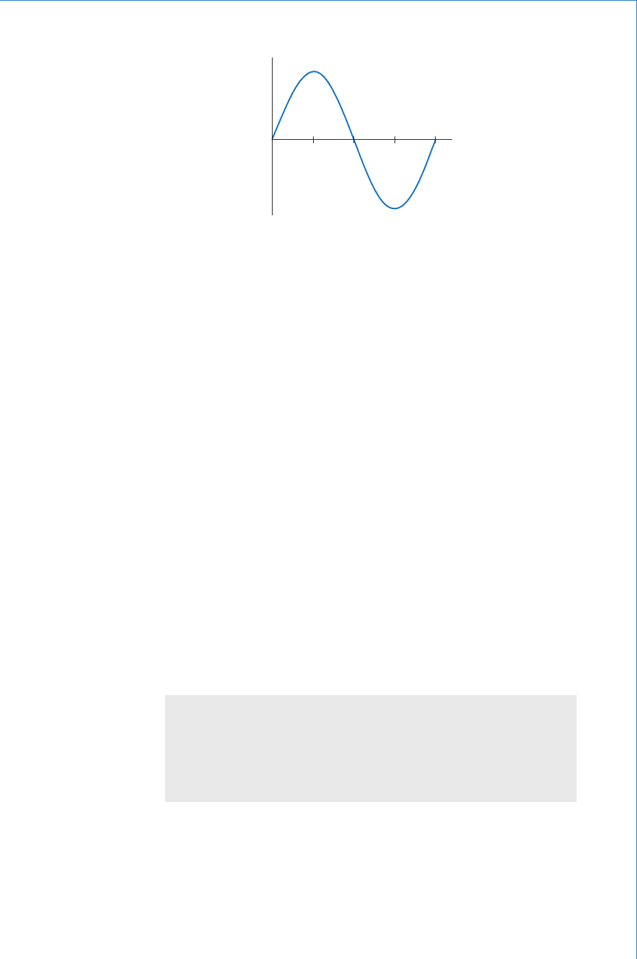
T/4
/2
3 /2 2
T/2
3 T/4 T t (s)
t (rad)
emf (V)
0
Fig. 6.3

202
Fundamental Electrical and Electronic Principles
Worked Example 6.1
Q An alternating voltage is represented by the expression v 35 sin(314.2 t ) volt. Determine, (a) the
maximum value, (b) the frequency, (c) the period of the waveform, and (d) the value 3.5 ms after it
passes through zero, going positive.
A
(a) v 35 sin(314.2t) volt
and comparing this to the standard,
vV ft
V
m
m
sin( ) volt we can see that:
V
2
35
Ans
(b) Again, comparing the two expressions:
2342
342
2
50
f
f
1
1
.
.
so, Hz Ans
(c)
T
f
T
11
50
20
second
so, ms Ans
(d)
When ms; then:
sin( ) volt
sin(
t
v
35
35 2 50 3 5 0
35
3
.
.
.
1
1 0099
35 0 89
39
)*
.
therefore, V
1
11v . Ans
*The term inside the brackets is an angle in RADIAN. You must therefore
remember to switch your calculator into the RADIAN MODE.
So far, we have dealt only with an alternating voltage. However, all
of the terms and defi nitions covered are equally applicable to any
alternating quantity. Thus, exactly the same techniques apply to a.c.
currents, fl uxes, etc. The same applies to mechanical alternating
quantities involving oscillations, vibrations, etc.
Worked Example 6.2
Q For a current, i 75 sin(200 t ) milliamp, determine (a) the frequency, and (b) the time taken for it to
reach 35 mA, for the rst time, after passing through zero.
A
(a)
it
ift
m
75 200
2
sin( ) milliamp
sin( ) amp
I
so,
and Hz
2 200
200
2
00
f
f
1 Ans
Alternating Quantities
203
(b)
35 75 200
35
75
200 0 4667
sin( ) milliamp
sin( )
t
t .
therefore, sin *
rad
so,
200 0 4667
0 4855
0 4855
200
t
t
1
.
.
.
00 773. ms Ans
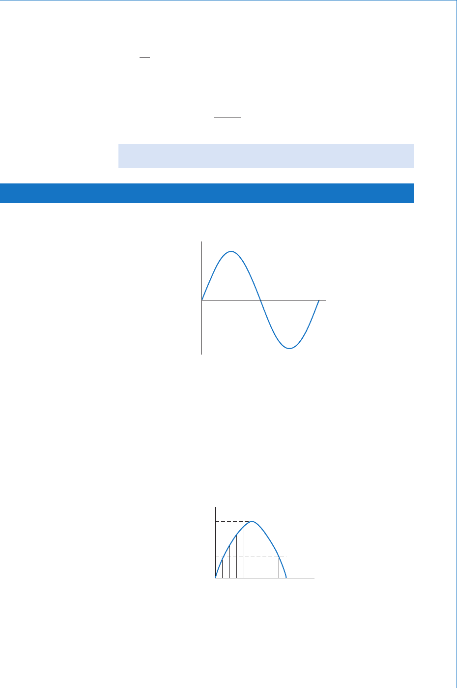
t (s)
0
Fig. 6.4
i
1
i
3
I
av
I
m
i
n
t (s)
Fig. 6.5
6.4 Average Value
Figure 6.4 shows one cycle of a sinusoidal current.
A number of equally spaced intervals are selected, along the time axis of
the graph. At each of these intervals, the instantaneous value is determined.
* Remember , use RADIAN mode on your calculator.
From this it is apparent that the area under the curve in the positive half
is exactly the same as that for the negative half. Thus, the average value
over one complete cycle must be zero. For this reason, the average
value is taken to be the average over one half cycle. This average may
be obtained in a number of ways. These include, the mid-ordinate rule,
the trapezoidal rule, Simpson ’ s rule, and integral calculus. The simplest
of these is the mid-ordinate rule, and this will be used here to illustrate
average value; see Fig. 6.5 .

204
Fundamental Electrical and Electronic Principles
This results in values for a number of ordinates, i
1
, i
2
, …, i
n
, where n is the
number of ordinates chosen. The larger the number of ordinates chosen,
the more accurate will be the fi nal average value obtained. The average is
simply found by adding together all the ordinate values, and then dividing
this fi gure by the number of ordinates chosen, thus
I
iii i
n
av
n
123
The average value will of course depend upon the shape of the
waveform, and for a sinewave only it is
II I
av m m
2
0 637
. (6.8)
Worked Example 6.3
Q A sinusoidal alternating voltage has an average value of 3.5 V and a period of 6.67 ms. Write down the
standard (trigonometrical) expression for this voltage.
A
V
av
3.5 V; T 6.67 10
3
s
The standard expression is of the form v V
m
sin (2 ft) volt
VV
V
V
VV
f
T
av m
m
av
m
0 637
0 637
35
0 637
55
.
.
.
.
.
volt
so, volt
h
1
eertz Hz
and, Hz
sin ( ) volt
so,
1
1
1
667 10
50
55 2 50
3
.
.
f
vt
vvt 5 5 300. sin ( )volt Ans
Worked Example 6.4
Q For the waveform speci ed in Example 6.3 above, after the waveform passes through zero, going
positive, determine its instantaneous value (a) 0.5 ms later, (b) 4.5 ms later, and (c) the time taken for
the voltage to reach 3 V for the rst time.
A
(a) t 0.5 10
3
s; (b) t 4.5 10
3
s; (c) v 3 V
(a)
vV
m
sin ( ) volt
sin
thus
300 0 5 0
55 047 2
55 0454
3
.
..
..
1
1
,, V v 25. Ans
Alternating Quantities
205
(b)
v
55 300 45 0
55 424
55 089
3
..
..
..
sin ( ) volt
sin
()
a
1
1
1
nnd, V v 49. Ans
Note: Remember that the expression inside the brackets is an angle in RADIAN.
(c)
3 5 5 300
300
3
55
0 5455
300
.
.
.
sin ( ) volt
so, sin ( )
sin
t
t
t
1
11
1
rad
and, ms
0 5455 0 5769
0 5769
300
62 0
06 2
4
..
.
.
.
t
t
AAns
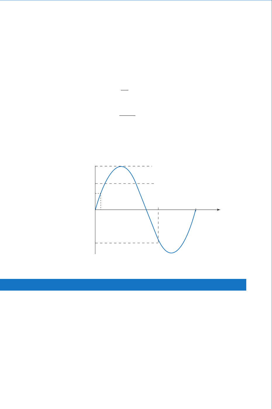
A sketch graph illustrating these answers is shown in Fig. 6.6 .
4.5
V
av
V
m
5.5
3.5
6.67
2.5
0.5
4.9
0
t (ms)
v (V)
Fig. 6.6
6.5 r.m.s. Value
The r.m.s. value of an alternating current is equivalent to that value of
direct current, which when passed through an identical circuit, will
dissipate exactly the same amount of power. The r.m.s. value of an a.c.
thus provides a means of making a comparison between a.c. and d.c.
systems.
The term r.m.s. is an abbreviation of the square Root of the Means
Squared. The technique for fi nding the r.m.s. value may be based
on the same ways as were used to fi nd the average value. However,
the r.m.s. value applies to the complete cycle of the waveform. For
simplicity, we will again consider the use of the mid-ordinate rule
technique.
206
Fundamental Electrical and Electronic Principles
Considering Fig. 6.5 , the ordinates would be selected and measured
in the same way as before. The value of each ordinate is then squared.
The resulting values are then summed, and the average found. Finally,
the square root of this average (or mean) value is determined. This is
illustrated below:
I
iii i
n
rms
n
1
2
2
2
3
22
…
and, for a sinewave only, II I
rms m m
1
2
0 707. (6.9)
Other waveforms will have a different ratio between r.m.s. and peak values.
Note: The r.m.s. value of an a.c. is the value normally used and quoted.
For example, if reference is made to a 240 V a.c. supply, then 240 V i s
the r.m.s. value. In general therefore, if an unqualifi ed value for an a.c.
is given, then the assumption is made that this is the r.m.s. value. Since
r.m.s. values are those commonly used, the subscript letters r.m.s. are
not normally included. I
rms
has been used above, simply for emphasis.
The following convention is used:
i, v, e, represent instantaneous values
I
av
, V
av
, E
av
, represent average values
I
m
, V
m
, E
m
, represent maximum or peak values, or amplitude
I, V, E, represent r.m.s. values
peak factor
maximum value
r.m.s. value
or
V
V
m
m
0 707
2 1 414
.
.
Worked Example 6.5
Q Calculate the amplitude of the household 240 V supply.
A
Since this supply is sinusoidal, then the peak factor will be
2
, so
VV
V
m
m
2 2 240
339 4
volt
so, V . Ans
6.6 Peak Factor
This is defi ned as the ratio of the peak or maximum value, to the r.m.s.
value, of a waveform. Thus, for a sinewave only

Alternating Quantities
207
Worked Example 6.6
Q A non-sinusoidal waveform has a peak factor of 2.5, and an r.m.s. value of 240 V. It is proposed to use
a capacitor in a circuit connected to this supply. Determine the minimum safe working voltage rating
required for the capacitor.
A
peak factor ; V
volt
so, V
2 5 240
25 25 240
600
.
..
V
VV
V
m
m
Thus the absolute minimum working voltage must be 600 V Ans
In practice, a capacitor having a higher working voltage would be
selected. This would then allow a factor of safety.
6.7 Form Factor
As the name implies, this factor gives an indication of the form or
shape of the waveform. It is defi ned as the ratio of the r.m.s. value to
the average value.
Thus, for a sinewave ,
form factor
r.m.s. value
average value
so, form f
0 707
0 637
.
.
aactor 111.
For a rectangular waveform (a squarewave), form factor 1,
since the r.m.s. value, the peak value, and the average value are all
the same.
Worked Example 6.7
Q A rectangular coil, measuring 25 cm by 20 cm, has 80 turns. The coil is rotated, about an axis
parallel with its longer sides, in a magnetic eld of density 75 mT. If the speed of rotation is
3000 rev/min, calculate, from rst principles, (a) the amplitude, r.m.s. and average values of
the emf, (b) the frequency and period of the generated waveform, (c) the instantaneous value,
2 ms after it is zero.
A
0 25 0 2 80 0 075
3000
60
20
3
.. .m; m; ; T
rev/s; s
dNB
nt1
(a) e 2 NBℓv sin (2 ft ) volt
Now, we know the rotational speed n , but the above equation requires the
tangential velocity, v , in metre per second. This may be found as follows.

208
Fundamental Electrical and Electronic Principles
r
o
t
a
t
i
o
n
d
v
Fig. 6.7
Consider Fig. 6.7 ,
which shows the path travelled by the coil sides.
The circumference of rotation d metre 0.2 metre.
The coil sides travel this distance in one revolution.
The rotational speed n 3000/60 50 rev/s.
Hence the coil sides have a velocity, v 50 0.2 m/s.
Therefore, e 2 80 0.075 0.25 50 0.27 sin (2 ft ) volt
and emf is a maximum value when sin (2 ft ) 1
so,
V
E
E
m
m
28000750255002
94 25
.. .
.
Ans
Assuming a sinusoidal waveform:
EE
E
EE
m
av m
0 707 0 707 94 25
66 64
0 637 0 637 9
...
.
..
so, V
Ans
4425
60 04
.
.so, V E
av
Ans
Assuming a 2-pole eld system, then f n therefore f 5 0 H z Ans
(b)
T
f
T
11
50
20
s
so ms Ans
(c)
eE ft
m
sin( ) volt
sin ( )
s
2
94 25 2 50 2 0
94 25 0 5878
3
.
..
1
oo, V e 55 4. Ans
6.8 Recti ers
A rectifi er is a circuit which converts a.c. to d.c. The essential
component of any rectifi er circuit is a diode. This is a semiconductor
device, which allows current to fl ow through it in one direction only.
Alternating Quantities
209
It is the electronic equivalent of a mechanical valve, for example the
valve in a car tyre. This device allows air to be pumped into the tyre,
but prevents the air from escaping.
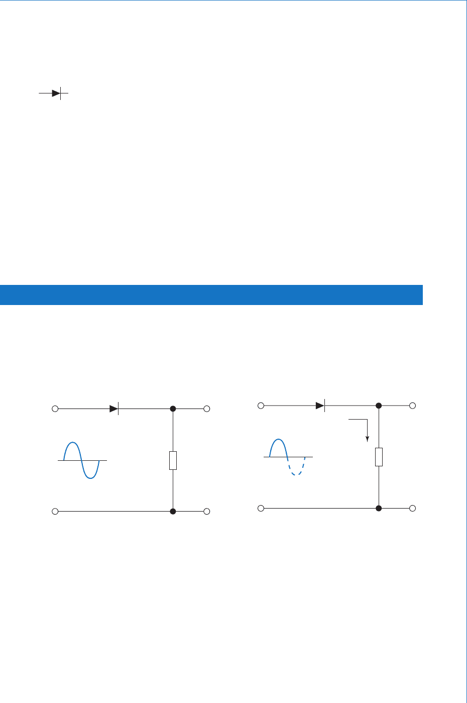
The circuit symbol for a diode is shown in Fig. 6.8 . The ‘ arrow head ’
part of the symbol is known as the anode. This indicates the direction
in which conventional current can fl ow through it. The ‘ plate ’ part
of the symbol is the cathode, and indicates that conventional current
is prevented from entering at this terminal. Thus, provided that the
anode is more positive than the cathode, the diode will conduct. This
is known as the forward bias condition. If the cathode is more positive
than the anode, the diode is in its blocking mode, and does not conduct.
This is known as reverse bias.
Note: The potentials at anode and cathode do not have to be positive
and negative. Provided that the anode is more positive than the cathode,
the diode will conduct. So if the anode potential is (say) 10 V, and the
cathode potential is 8 V, then the diode will conduct. Similarly, if
these potentials are reversed, the diode will not conduct.
6.9 Half-wave Recti er
This is the simplest form of rectifi er circuit. It consists of a single
diode, placed between an a.c. supply and the load, for which d.c. is
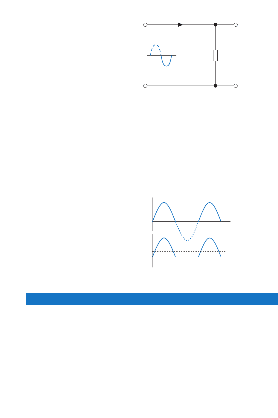
required. The arrangement is shown in Fig. 6.9 , where the resistor R
represents the load.
Fig. 6.8
Let us assume that, in the fi rst half cycle of the applied voltage, the
instantaneous polarities at the input terminals are as shown in Fig. 6.10 .
Under this condition, the diode is forward biased. A half sinewave of
current will therefore fl ow through the load resistor, in the direction
shown.
In the next half cycle of the input waveform, the instantaneous
polarities will be reversed. The diode is therefore reverse biased, and
no current will fl ow. This is illustrated in Fig. 6.11 .
R
output
input
Fig. 6.9
R
output
input
l
Fig. 6.10
210
Fundamental Electrical and Electronic Principles
R
output
input
Fig. 6.11
The graphs of the applied a.c. voltage, and the corresponding load
current, are shown in Fig. 6.12 . The load p.d. will be of exactly the
same waveshape as the load current. Both of these quantities are uni-
directional, and so by defi nition, are d.c. quantities. The ‘ quality ’ of the
d.c. so produced is very poor, since it exists only in pulses of current.
The average value of this current is determined over the time period,
0 to t
2
. The average value from 0 to time t
1
will be 0.637 I
m
. From t
1
to t
2
it will be zero. The average value of the d.c. will therefore be,
I
av
0.318 I
m
.
0
input
0
I
m
I
av
t
1
t
2
t (s)
t (s)
Fig. 6.12
6.10 Full-wave Bridge Recti er
Both the ‘ quality ’ and average value of the d.c. need to be improved.
This may be achieved by utilising the other half cycle of the a.c.
supply. The circuit consists of four diodes, connected in a ‘ bridge ’
confi guration, as shown in Fig. 6.13 .
We will again assume the instantaneous polarities for the fi rst half
cycle as shown. In this case, diodes D
1
and D
4
will be forward biased.
Diodes D
2
and D
3
will be reverse biased. Thus, D
1
and D
4
allow
current to fl ow, as shown. In the next half cycle, the polarities are
reversed. Hence, D
2
and D
3
will conduct, whilst D
1
and D
4
are reverse
biased. Current will therefore fl ow as shown in Fig. 6.14 . Notice that
