Pump Handbook by Igor J. Karassik, Joseph P. Messina, Paul Cooper, Charles C. Heald - 3rd edition
Подождите немного. Документ загружается.

13 PUMP TESTING 13.31
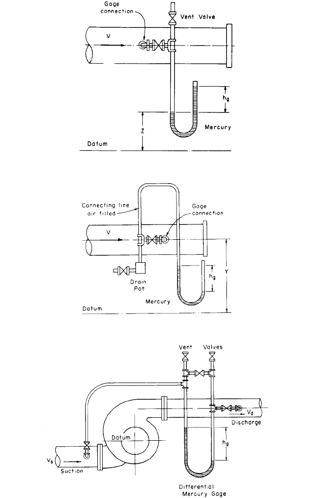
FIGURE 24 Head measurement
FIGURE 25 Head measurement
FIGURE 26 Head measurement
13.32 CHAPTER THIRTEEN
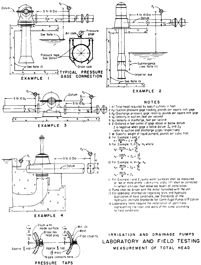
FIGURE 27 Head measurement. In SI units, hd = [(0.102 P
d
/W) Z
d
(/2g)]; h
s
= [(0.102 P
s
/W) Z
s
(/2g). (ft 0.3048 = m; psi 6.894 = kPa; pcf .016 = kg/liter)V
2
s
V
2
d
to avoid errors due to the difference between the temperature of the water in the gage and
that of the water in the pump.
DEFINITIONS AND SYMBOLS The symbols used throughout this section for expressing and
computing head are those used by the ASME Power Test Code
1
for pumps and the
Hydraulic Institute ANSI/HI 2000 Edition Pump Standards (Reference 13). The following
symbols apply to Figures 21 to 27 where temperature effects are negligible:

13 PUMP TESTING 13.33
H total head or dynamic head, ft (m) the energy increase per pound
(kilogram) of liquid imparted to the liquid by the pump and therefore the
algebraic difference between total discharge head and total suction head
(H h
d
h
s
);h
d
and h
s
are negative if the corresponding values at the
datum elevation are below atmospheric pressure
h
gd
discharge gage reading, ft (m) H
2
O
h
gs
suction gage reading, ft (m) H
2
O
Both the discharge gage and the suction gage can be direct-reading water manometers,
converted mercury manometers, or calibrated bourdon pressure gages.
Z
d
elevation of discharge gage, zero above datum elevation, ft (m)
Z
s
elevation of suction gage, zero above datum elevation, ft (m)
The quantities Z
d
and Z
s
are negative if the gage zero is below the datum elevation.
Y
d
elevation of discharge gage connection to discharge pipe above datum
elevation, ft(m)
Y
s
elevation of suction gage connection to suction pipe above datum eleva-
tion, ft (m)
The quantities Y
d
and Y
s
are negative if the gage connection to the pipe lies below the
datum elevation.
V
d
average water velocity in discharge pipe at discharge gage connection,
ft/s (m/s)
V
s
average water velocity in suction pipe at suction gage connection, ft/s (m/s)
h
d
total discharge head above atmospheric pressure at datum elevation, ft (m)
h
s
total suction head above atmospheric pressure at datum elevation, ft (m)
h
vs
velocity head in suction pipe ( ), ft (m)
h
vd
velocity head in discharge pipe ( ), ft (m)
NPSHA net positive suction head available total suction head in feet (meters) of
liquid absolute, determined at suction nozzle and referred to datum less
absolute vapor pressure of the liquid in feet (meters) of liquid pumped
(NPSHA h
a
H
vpa
h
s
)
h
sa
total suction head absolute (h
a
h
s
)
H
vpa
vapor pressure of liquid, ft (m) abs
h
a
atmosphere pressure, ft (m) abs
MEASURING HEAD WITH WATER GAGES The following examples illustrate how to calculate the
head in a centrifugal pump arrangement with gages either above or below atmospheric
pressure.
EXAMPLE The pressure at gage connection a in Figure 21 is above atmospheric pres-
sure, and the line between either the discharge or suction pipe and the corresponding
gage is filled completely with water. The following equations apply:
h
s
h
gs
Z
s
V
s
2
2g
h
d
h
gd
Z
d
V
d
2
2g
V
2
d
>2g
V
2
s
>2g

13.34 CHAPTER THIRTEEN
*Note: The use of mercury is restricted because of its toxicity. Alternative liquids or alternative measuring devices
are commonly used to avoid mercury contamination.
Note: The word water is used to represent the liquid being pumped. The provisions
are applicable to the pumping of other liquids, provided the gages and connecting lines
contain the liquid being pumped.
EXAMPLE The pressure at gage connection a in Figure 22 is below atmospheric pres-
sure. The following equation applies:
The negative sign of Z
s
indicates that the gage zero is located below the datum.
EXAMPLE
The pressure at gage connection a in Figure 23 is below atmospheric pres-
sure, and the line between either the discharge or suction pipe and the corresponding
gage is filled completely with air. The following equations apply:
Note: If a connecting pipe is air-filled, it must be drained before a reading is made.
Water cannot be used in the U tube if either h
dg
or h
ds
exceeds the height of the ris-
ing loop.
MEASURING HEAD WITH MERCURY GAGES*
The following examples illustrate the use of mer-
cury gages for measuring head in a centrifugal pump arrangement.
EXAMPLE
In Figure 24, the gage pressure is above atmospheric pressure and the con-
necting line is completely filled with water. The following equation applies:
where W
m
specific weight (mass) of mercury, lb/ft
3
(kg/liter)
W specific weight (mass) of liquid pumped, lb/ft
3
(kg/liter)
h
g
suction or discharge gage reading, ft (m) Hg
The quantities h,Z,Y, and V without subscripts apply equally to suction and dis-
charge head measurements.
EXAMPLE The gage pressure in Figure 25 is below atmospheric pressure, and the con-
necting line is completely filled with air, with a rising loop to prevent water from pass-
ing to the mercury column. The following equation applies
MEASURING HEAD WITH DIFFERENTIAL MERCURY GAGES* Figure 26 indicates a centrifugal
pump arrangement in which a differential mercury gage is used to measure head. When
h
W
m
W
h
g
Y
V
2
2g
h
W
m
W
h
g
Z
V
2
2g
h
s
h
gs
Y
s
V
s
2
2g
h
d
h
gd
Y
d
V
d
2
2g
h
s
h
gs
Z
s
V
s
2
2g

13 PUMP TESTING 13.35
this type of gage is used and the connecting lines are completely filled with water, the cor-
rect equation is
In addition to the differential gage, a separate suction gage can be used, as shown in
Figures 22 and 25. The equation in this case is
MEASURING HEAD WITH BOURDON GAGES An example of a centrifugal pump arrangement that
uses calibrated bourdon gages for head measurement is shown in Example 3 of Figure 27,
with the gage pressure above atmospheric pressure. The distances Z
s
and Z
d
are measured
to the center of the gage and are negative if the center of the gage lies below the datum line.
MEASURING HEAD ON VERTICAL SUCTION PUMPS IN SUMPS AND CHANNELS
In vertical-shaft
pumps drawing water from large open sumps and having inlet passages whose length
does not exceed about three inlet opening diameters, such inlet pieces having been fur-
nished as part of the pump, the total head should be the reading of the discharge con-
nection in feet (meters) plus the vertical distance from the gage centerline to the free
water level in the sump in feet (meters) (Example 2 of Figure 27).
Power Measurement The pump input power may be determined with a calibrated
motor, a transmission dynamometer, or a torsion dynamometer. The Hydraulic Institute
ANSI/HI 2000 Edition Pump Standards (Reference 13) are generally used as the basis for
most power measurement procedures.
CALIBRATED MOTORS
When pump input power is to be determined with a calibrated motor,
the power input should be measured at the terminals of the motor to exclude any line
losses that may occur between the switchboard and the driver. Certified calibration curves
of the motor must be obtained. The calibration should be conducted on the motor in ques-
tion and not on a similar machine. Such calibrations must indicate the true input-output
value of motor efficiency and not some conventional method of determining an arbitrary
efficiency. Calibrated laboratory-type electric meters and transformers should be used to
measure power input to all motors.
TRANSMISSION DYNAMOMETERS The transmission, or torque-reaction, dynamometer con-
sists of a cradled electric motor with its frame and field windings on one set of bearings
and the rotating element on another set, so the frame is free to rotate but is restrained
by means of some weighting or measuring device.
When pump input power is to be determined with a transmission dynamometer, the
unloaded and unlocked dynamometer must be properly balanced prior to the test at the
same speed at which the test is to be run.The balance should be checked against standard
weights. After the test the balance must be rechecked to assure that no change has taken
place. In the event of an appreciable change, the test should be rerun. An accurate mea-
surement of speed is essential and should not vary from the pump rated speed by more
than 1%. Power input is calculated as shown later in this section under “Computations.”
TORSION DYNAMOMETERS The torsion dynamometer consists of a length of shafting whose
torsional strain when rotating at a given speed and delivering a given torque is measured
by some standard method. When pump input power is to be determined with a torsion
dynamometer, the unloaded dynamometer should be statically calibrated prior to the test.
This is done by measuring the angular deflection for a given torque.
Immediately before and after the test, the torsion dynamometer must be calibrated
dynamically at the rated speed. The best and simplest method to accomplish this is to use
the actual job driver to supply power and use a suitable method of loading the driver over
the entire range of the pump to obtain the necessary calibrations. The calibration of the
h
s
W
m
W
h
gs
Z
V
s
2
2g
H a
W
m
W
1bh
g
V
d
2
2g
V
s
2
2g

13.36 CHAPTER THIRTEEN
torsion dynamometer after the pump tests should be within 0.5% of the original calibra-
tion. During the test runs the speed should not vary from the pump rated speed by more
than 1%. The temperature of the torsion dynamometer during the test runs must be
within 10°F (6°C) of the temperature when the dynamic calibrations were made. All tor-
sion dynamometer calibrations should be witnessed and approved by all parties to the
test. In the event of a variation greater than allowed, a rerun of the test must be made.
Power input calculations are shown in the following text.
Speed Measurement The speed of the pump under test is determined by one of the fol-
lowing methods:
Revolution counter (manual or automatic)
Tachometer
Stroboscopic device
Electronic counter
In all cases, the instruments used must be carefully calibrated before the test to demon-
strate that they will produce the required speed readout to within the desired accuracy.
Accepted accuracy is usually ;0.1%. Should cyclic speed change result in power fluctuations,
at least five equally spaced, timed readings should be taken to give a satisfactory mean speed.
COMPUTATIONS _____________________________________________________
Pump Power
POWER OUTPUT The water power, or useful work, done by the pump is found by the formula
in USCS units
in SI units
If the liquid has a specific gravity of 1 and the specific weight of the liquid is 62.3 lb/ft
3
(1.0 kg/liter) at 68°F (20°C), the formula is
in USCS units
in SI units
POWER INPUT The brake power required to drive the pump is found by the formula
in USCS units
in SI units
where pump efficiency is obtained from the formula
(used as a decimal)
The electric power input to the motor is
Pump efficiency
output
input
whp
bhp
wkW
bkW
bkW
9.8 m
3
>h total head in m
pump efficiency
bhp
gpm total head in ft
3960 pump efficiency
wkW 9.8 m
3
>h head in m
whp
gpm head in ft
3960
wkW
kg of liquid pumped>min total head in m of liquid
6131
whp
lb of liquid pumped>min total head in ft of liquid
33,000

13 PUMP TESTING 13.37
in USCS units
in SI units
The kilowatt input to the motor is
Pump Efficiency The pump efficiency is
For an electric-motor-driven pumping unit, the overall efficiency is
In many specifications, it is required that the actual job motor be used to drive the
pump during shop or field testing. Using this test setup, the overall efficiency then becomes
what is commonly called “wire-to-water” efficiency, which is expressed by the formula
Speed Adjustments The best and standard practice in testing pump speed is to use
the actual job motor to drive the pump under test. However, for purposes of plotting test
results, it becomes necessary to correct the test values at test speed to rated pump speed.
The rated pump speed should always be less than the test speed because even a small
increase in speed beyond the test speed may result in going into an unstable zone of the
pump. Also, it is recommended that the speed change from test speed to rated or specified
speed not be greater than 3%.
To adjust pump flow rate, head, power, and NPSH from the values recorded during test
to another speed, the following formulas
(10)
should be used:
Capacity:
where Q
1
flow rate at test speed, gpm (m
3
/h)
Q
2
flow rate at rated speed, gpm (m
3
/h)
N
1
test speed, rpm
N
5
rated speed, rpm
Head:
where H
1
head at test speed, ft (m)
H
2
head at rated speed, ft (m)
Power:
in USCS units hp
2
a
N
2
N
1
b
3
hp
1
H
2
a
N
2
N
1
b
2
H
1
Q
2
N
2
N
1
Q
1
Overall efficiency
water power
electric power input
whp
ehp
wkW
kW
Overall efficiency pump efficiency motor efficiency
Pump efficiency
output
input
whp
bhp
wkW
bkW
gpm head 0.746
3960 pump efficiency motor efficiency
kW input
bhp 0.746
motor efficiency
kW
9.8 m
3
>h head in m
pump efficiency motor efficiency
ehp
bhp
motor efficiency
gpm head in ft
3960 pump efficiency motor efficiency

13.38 CHAPTER THIRTEEN
in SI units
where hp
1
power at test speed, hp
hp
2
power at rated speed, hp
kW
1
power at test speed, kW
kW
2
power at rated speed, kW
Net positive suction head:
where NPSH
1
net positive suction head at test speed, ft (m)
NPSH
2
net positive suction head at rated speed, ft (m)
Shop or field testing at either reduced or increased speed should be permitted only
when absolutely no alternatives are available. It is recommended, if reduced or increased
speed tests are used as official performance tests, that the specifications state the test
head and speed and that the performance warranties be based on the specified head and
speed conditions.
If reduced or increased speed tests are considered, certain affinity laws must be
observed to maintain hydraulic similarity between actual and test conditions.These affin-
ity law relationships can be expressed by
where test Q
1
flow rate and H
1
head at N
1
rpm
actual Q flow rate and H head at N rpm
RECORDS __________________________________________________________
Data
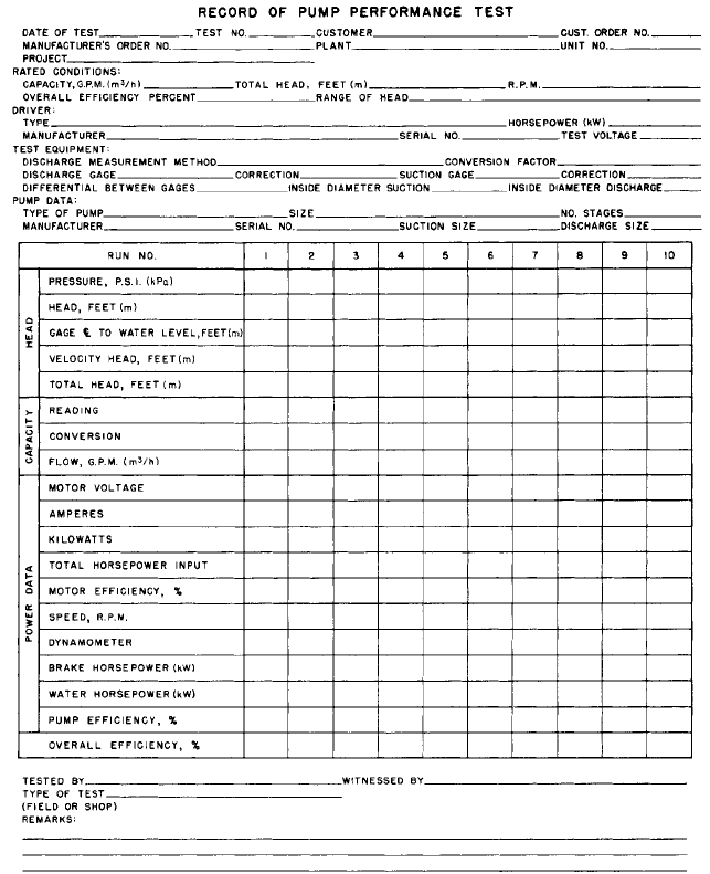
There probably are as many test data forms as there are test laboratories. Each
may or may not have an advantage for its particular application. A form for recording
pump performance data is shown in Figure 28.
The manufacturer’s serial number, type, and size or other means of identification of
each pump and driver involved in the test should be carefully recorded in order that mis-
takes in identity may be avoided. The dimensions and physical conditions not only of the
machine tested but of all associated parts of the plant which have any important bearing
on the outcome of a test, should be noted.
Normal practice suggests that one test run be either at or as near as possible to the
rated condition and that at least three runs be within the specified range of heads.
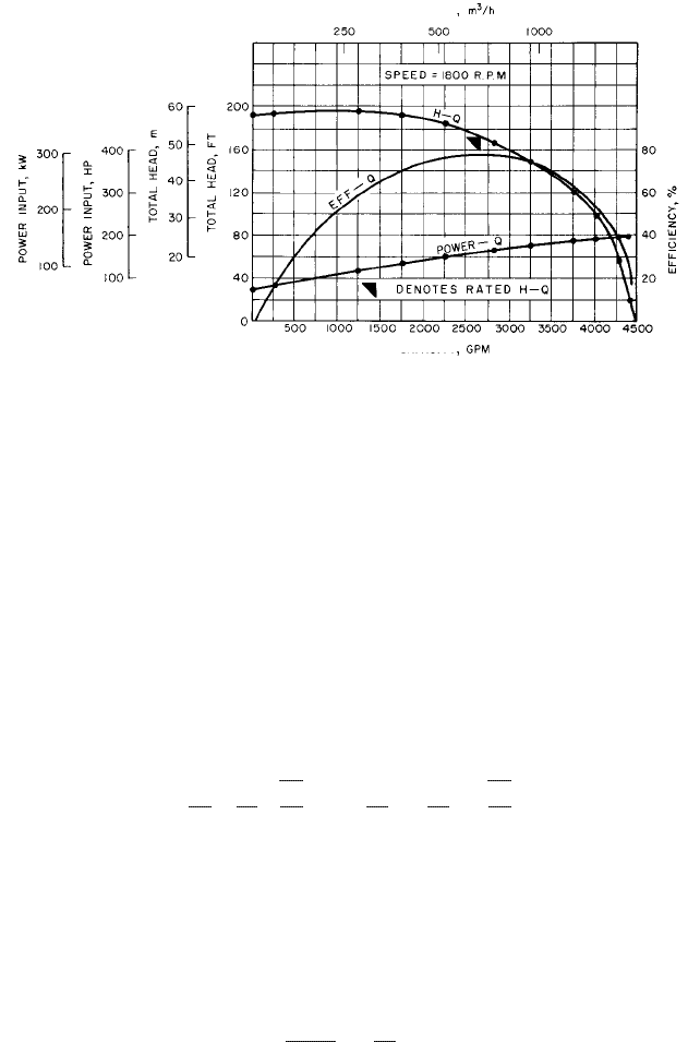
Plotting Test Results In plotting curves from the test results, it should be kept in mind
that any one point may be in error but that all the points should establish a trend.
Unless some external factor is introduced to cause an abrupt change, a smooth curve
can be drawn for the points plotted, not necessarily through each and every one. Figure 29
is a graphic representation showing the determination of pump performance with the total
head, power input, and efficiency in percent, all plotted on the same graph with the capac-
ity as the abscissa.
Reports In some instances a preliminary report may be issued as part of a contract
agreement. However, normally a final report is all that is required.
On shop tests of relatively small pumps, the test log and plotted results constitute the
entire report. Reports get progressively more involved as pumps become larger. Where
Q
1
Q
N
1
N
a
H
1
H
b
1>2
NPSH
2
a
N
2
N
1
b
2
NPSH
1
kW
2
a
N
2
N
1
b
3
kW
1
13 PUMP TESTING 13.39
FIGURE 28 Record of pump performance test
model testing is used, the final report is a complete record of the agreements, inspections,
personnel, calibration data, sample computations, tabulations, descriptions, discussions, etc.
MODEL TESTING _____________________________________________________
Models are tested for one or more of the following purposes:
1. To develop new ideas and new designs
2. To give the manufacturer a range of warranties for performance and efficiency
13.40 CHAPTER THIRTEEN
FLOW RATE
FLOW RATE
FIGURE 29 Plotted pump performance
3. To give the buyer some assurance that requirements are being met
4. To replace or supplement field testing of a prototype
5. To compare performances of several models
Model testing in advance of final design and installation of a large unit not only pro-
vides advance assurance of satisfactory performance but allows for alterations in time for
incorporation into the prototype.
Testing Procedures The model should have complete geometric similarity to the pro-
totype in all wetted parts between the intake and discharge sections of the pump. The
model should be tested in the same horizontal- or vertical-shaft position as the prototype.
The speed of the model should be such that, at the test head, the specific speed for each
test run is the same as that of the installed unit or prototype. Unless otherwise specified,
the suction head or suction lift should give the same (cavitation factor) value.
If model and prototype diameters are D
1
and D, respectively, then the model speed N
1
and capacity Q
1
under the test head H
1
must agree with the relations
and
In testing a model of reduced size under the previous conditions, complete hydraulic
similarity will not be secured unless the relative roughness of the impeller and pump cas-
ing surfaces are the same. With the same surface texture in model and prototype, the
model efficiency will be lower than that of the prototype, and greater relative clearances
and shaft friction in the model will also reduce its efficiency.
The efficiency of a pump model can conveniently be stepped up to match the prototype
efficiency by applying a formula of the same general form as the Moody formula used for
hydraulic turbines:
The exponent n should be determined for a given laboratory and given type of pump on
the basis of an adequate number of comparisons of the efficiencies of models and proto-
types, with consistent surface finish in model and prototype.The Hydraulic Institule Stan-
1 e
1
1 e
a
D
D
1
b
n
B
H
1
H
Q
1
Q
a
D
1
D
b
2
B
H
1
H
N
1
N
D
D
1