Pump Handbook by Igor J. Karassik, Joseph P. Messina, Paul Cooper, Charles C. Heald - 3rd edition
Подождите немного. Документ загружается.

12.6 CHAPTER TWELVE
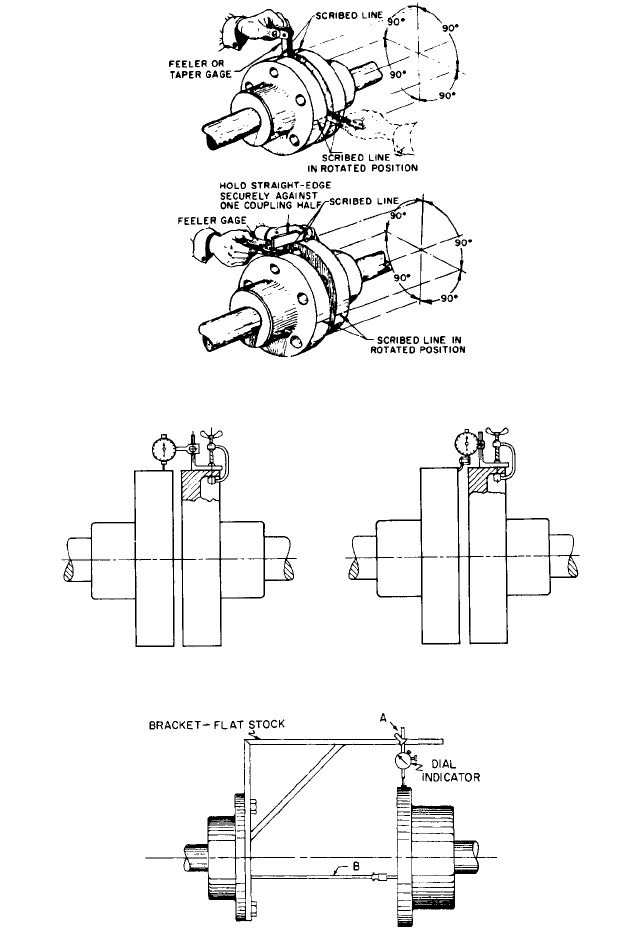
FIGURE 5 Coupling alignment using feeler gages
FIGURE 6 Use of dial indicator for face-and-rim alignment of standard coupling
FIGURE 7 Use of dial indicator for face-and-rim alignment of spacer-type coupling
to clamp a suitable extension arm or bracket long enough to extend across the space
between the coupling hubs. The dial indicator is mounted on this arm, and alignment is
checked for both concentricity of the hub diameters and parallelism of the hub faces.
12 INSTALLATION, OPERATION, AND MAINTENANCE 12.7
Changing the arm from one hub to the other provides an additional check. The dial exten-
sion bracket must be checked for sag, and readings must be corrected accordingly.
The clearance between the faces of the coupling hubs and the ends of the shafts should
be such that they cannot touch, rub, or exert a pull on either pump or driver. The amount
of this clearance may vary with the size and type of coupling used. Sufficient clearance will
allow unhampered endwise movement of the shaft of the driving element to the limit of its
bearing clearance. On motor-driven units, the magnetic center of the motor will determine
the running position of the motor half-coupling. This position should be checked by run-
ning the motor uncoupled. This will also permit checking the direction of rotation of the
motor. If current is not available at the time of installation, move the motor shaft in both
directions as far as the bearings will permit and adjust the shaft centrally between these
limits. The unit should then be assembled with the correct gap between the coupling
halves.
Large horizontal sleeve-bearing motors are not generally equipped with thrust bear-
ings. The motor rotor is permitted to float, and as it will seek its magnetic center, an axial
force of rather small magnitude can cause it to move off this center. Sometimes it will move
enough to cause the shaft collar to contact and possibly damage the bearing.To avoid this,
a limited-end-float coupling is used between the pump and the motor on all large units to
restrict the motor rotor (Subsection 6.3.1). The setting of axial clearances for such units
should be given by the manufacturer in the instruction books and elevation drawings.
When the pump handles a liquid at other than ambient temperature or when it is dri-
ven by a steam turbine, the expansion of the pump or turbine at operating temperature
will alter the vertical alignment. Alignment should be made at ambient temperature with
suitable allowances for the changes in pump and driver centerlines after expansion. The
final alignment must be made with the pump and driver at their normal temperatures
and adjusted as required before the pump is placed into permanent service.
For large installations, particularly with steam-turbine-driven pumps, more sophisti-
cated alignment methods are sometimes employed, using proximity probes and optical
instruments. Such procedures permit checking the effect of temperature changes and
machine strains caused by piping stresses while the unit is in operation. When such pro-
cedures are recommended, they are included with the manufacturer’s instructions.
When the unit has been accurately leveled and aligned, the hold-down bolts should be
gently and evenly tightened before grouting. The alignment must be rechecked after the
suction and discharge piping has been bolted to the pump to test the effect of piping
strains.This can be done by loosening the bolts and reading the movement of the pump, if
any, with dial indicators.
The pump and driver alignment should be occasionally rechecked because misalign-
ment may develop from piping strains after a unit has been operating for some time.This
is especially true when the pump handles hot liquids because there may be a growth or
change in the shape of the piping. Pipe flanges at the pump should be disconnected after
a period of operation to check the effect of the expansion of the piping, and adjustments
should be made to compensate for this.
For a further discussion of hot and cold alignment, face-and-rim versus reverse dial
methods measurement of dial bracket sag, and graphical alignment plotting procedure,
refer to Subsection 2.3.3.
Grouting Ordinarily, the baseplate is grouted before the piping connections are made
and before the alignment of the coupling halves is finally rechecked.The purpose of grout-
ing is to prevent lateral shifting of the baseplate, to increase the mass to reduce vibra-
tion, and to fill in irregularities in the foundation. Generally, it is recommended that all
permanently installed pumping equipment be supported by a reinforced concrete foun-
dation. Some pumps that require an elevated installation may be supported on structural
steel structures, but care must be taken to ensure that such structures are of adequate
stiffness and strength.
Foundation dimensions must consider the size and arrangement of the pump and dri-
ver, the piping arrangement and anticipated piping loads, anchor bolt placement, and min-
imum dimensions required for servicing the equipment. Vertically suspended canned

12.8 CHAPTER TWELVE
FIGURE 8 Application of grouting. Grout is added until the entire space under the base is filled. Holes in the
base (arrow) allow air to escape and permit working of the grout to release air pockets.
pump foundations should be designed so the pump can is directly attached to a mounting
plate and is removable without disturbing the grout.
Foundation materials must be properly resistant to chemicals and oils. If the envi-
ronment is aggressive, protective coatings or covers should be considered to protect the
foundation and reinforcing steel. Two types of grout are commonly used: epoxy and
cement-based. Epoxy grout, although usually more expensive, has significant advan-
tages in higher bond strength and nonporous finished surface characteristics that gen-
erally make it the material of choice for most pump installations.
When the foundation has been prepared, the grout material has been selected, and the
baseplate has been properly positioned on the foundation, a preliminary coupling align-
ment is made to ensure that final alignment is possible after the baseplate is finally
grouted. After this alignment check is successfully accomplished, the grout is added
through the holes in the baseplate. To retain the grout in place, a leak-tight form is built
around the outside of the baseplate. Grout is added until the entire space under the base-
plate is filled to the top of the underside (Figure 8). The grout holes and vent holes in the
baseplate allow air to escape as the grout fills the cavity. A stiff wire may be used through
the grout holes to work the grout and release any air pockets. It is usually best to start
at one end and force the air out as the grout proceeds toward the other end of the base-
plate. Leveling shims and wedges used to level the baseplate should be left in place after
grouting.
When the grout has properly cured, voids have been filled and forms have been
removed, the exposed surfaces of the grout and foundation can be properly finished. The
foundation anchor/hold-down bolts should be finally torqued to the proper values and the
coupling halves can be rechecked for alignment.
The pump and driver alignment must be rechecked thoroughly after the grout has
hardened permanently, and at reasonable intervals thereafter.
Doweling of Pump and Driver When the pump handles hot liquids, doweling of both
the pump and its driver should be delayed until the unit has been operated. A final
recheck of alignment with the coupling bolts removed and with the pump and driver at
operating temperature is advisable before doweling.
Large pumps handling hot liquids are usually doweled near the coupling end, allowing
the pump to expand from that end out. Sometimes the other end is provided with a key
and a keyway in the casing foot and the baseplate.
PIPING _____________________________________________________________
Suction Piping
The suction piping should be as direct and short as possible. If a long
suction line is required, the pipe size should be increased to reduce frictional losses. (The
exception to this recommendation is in the case of boiler-feed pumps, where difficulties
may arise during transient conditions of load change if the suction piping volume is exces-
sive. This is a special and complex subject, and the manufacturer should be consulted.)
Where the pump must lift the liquid from a lower level, the suction piping should be laid
out with a continual rise toward the pump, avoiding high spots in the line to prevent the
formation of air pockets. Where a static suction head will exist, the pump suction piping
should slope continuously downward to the pump.
12 INSTALLATION, OPERATION, AND MAINTENANCE 12.9
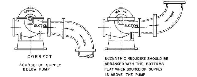
FIGURE 9 Recommended installation of reducers at pump suction
Generally, the suction line is larger than the pump suction nozzle and eccentric reduc-
ers should be used. If the source of supply is above the pump centerline, the reducer should
be installed straight side up. If the source of supply is above the pump, the straight side of
the reducer should be at the bottom (Figure 9). Installing eccentric reducers with a change
in diameters greater than 4 in (10 cm) could disturb the suction flow. If such a change is
necessary, it is advisable to use properly vented concentric reducers.
Elbows and other fittings next to the pump suction should be carefully arranged, or the
flow into the pump impeller will be disturbed. Long-radius elbows are preferred for suc-
tion lines because they create less friction and provide a more uniform flow distribution
than standard elbows.
It is extremely important to avoid the formation of vortices at the suction of both wet-
pit and dry-pit pump installations. For a discussion of this and other suction conditions
recommendations, see Sections 10.1 and 10.2.
Discharge Piping Generally both a check valve and a gate valve are installed in the
discharge line. The check valve is placed between the pump and the gate valve and pro-
tects the pump from reverse flow in the event of unexpected driver failure or from reverse
flow from another operating pump. The gate valve is used when priming the pump or
when shutting it down for inspection and repairs. Manually operated valves that are dif-
ficult to reach should be fitted with a sprocket rim wheel and chain. In many cases, dis-
charge gate valves are motorized and can be operated by remote control.
Piping Strains Cast iron pumps are never provided with raised face flanges. If steel suc-
tion or discharge piping is used, the pipe flanges should be of the flat-face and not the
raised-face type. Full-face gaskets must be used with cast iron pumps.
Piping should not impose excessive forces and moments on the pump to which it is con-
nected because these might spring the pump or pull it out of position. Piping flanges must
be brought squarely together before the bolts are tightened. The suction and discharge pip-
ing and all associated valves, strainers, and so on should be supported and anchored near
to but independent of the pump, so no strain will be transmitted to the pump casing.
There are four factors to be considered in determining the effect of nozzle loads: mate-
rial stress in pump nozzles resulting from forces and bending moments, distortion of inter-
nal moving parts affecting critical clearances, stresses in pump hold-down bolts, and
distortion in pump supports and baseplates resulting in driver coupling misalignment.
API Standard 610 (Centrifugal Pumps for Refinery, Heavy Duty Chemical, and Gas Indus-
try Services) provides guidelines for limiting the magnitude of nozzle loads and moments
on pumps with suction nozzles 16 in (41 cm) and smaller and with casings constructed of
steel or alloy steel.
With large pumps or when major temperature changes are expected, the pump manu-
facturer generally indicates to the user the maximum moments and forces that can be
12.10 CHAPTER TWELVE
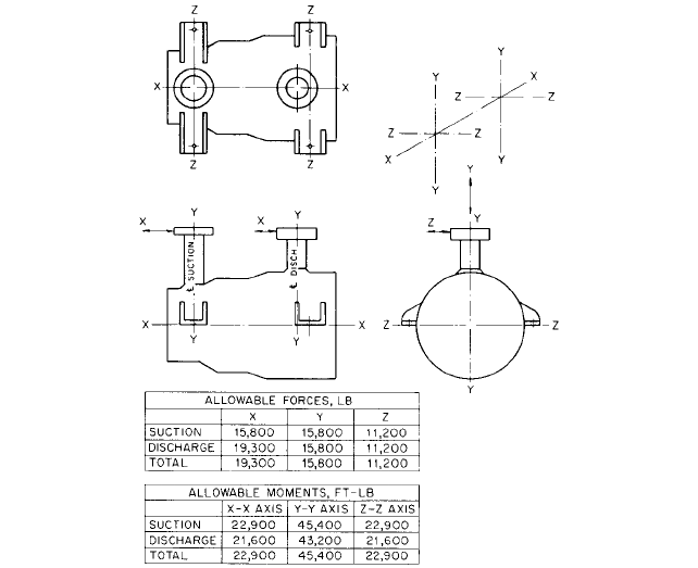
FIGURE 10 Diagram of typical permissible pipe stresses and moments for a radially split double-casing
multistage pump with top suction and discharge (1 N = 0.225 lb; 1 N
•
m = 0.737 ft
•
lb).
imposed on the pump by the piping.A typical diagram is illustrated in Figure 10 for a radi-
ally split double-casing multistage pump with top suction and discharge.
Expansion Joints Expansion joints are sometimes used in the discharge and suction
piping to avoid transmitting any piping strains caused by misalignment or by expansion
when hot liquids are handled. On occasion, expansion joints are formed by looping the
pipe. More often, they are of the slip-joint or corrugated-diaphragm type. However, they
transmit to the pump a force equal to the area of the expansion joint times the pressure
in the pipe. These forces can be of very significant magnitude, and it is impractical to
design the pump casings, baseplates, and so on to withstand them. Consequently, when
expansion joints are used, a suitable pipe anchor must be installed between them and the
pump proper. Alternately, tie rods can be used to prevent the forces from being transmit-
ted to the pump.
Suction Strainers Except for certain special designs, pumps are not intended to han-
dle liquid containing foreign matter. If the particles are sufficiently large, such foreign
matter can clog the pump, reduce its capacity, or even render it altogether incapable of
pumping. Small particles of foreign matter may cause damage by lodging between close
running clearances. Therefore, proper suction strainers may be required in the suction
lines of pumps not specially designed to handle foreign matter.
In such an installation, the piping must first be thoroughly cleaned and flushed. The
recommended practice is to flush all piping to waste before connecting it to the pump.
Then a temporary strainer of appropriate size should be installed in the suction line as
close to the pump as possible. This temporary strainer may have a finer mesh than the

12 INSTALLATION, OPERATION, AND MAINTENANCE 12.11
FIGURE 11 Arrangement for warm-up through pump casing drain connection
permanent strainer installed after the piping has been thoroughly cleaned of all possible
mill scale or other foreign matter. The size of the mesh is generally recommended by the
pump manufacturer. For further details on strainers, see Sections 8.1 and 10.1.
Venting and Draining Vent valves are generally installed at one or more high points
of the pump casing waterways to provide a means of escape for air or vapor trapped in
the casing. These valves are used during the priming of the pump or during operation if
the pump should become air- or vapor-bound. In most cases, these valves need not be piped
up away from the pump because their use is infrequent, and the vented air or vapors can
be allowed to escape into the surrounding atmosphere. On the other hand, vents from
pumps handling flammable, toxic, or corrosive fluids must be connected in such a way that
they endanger neither the operating personnel nor the installation. The suction vents of
pumps taking liquids from closed vessels under vacuum must be piped to the source of
the pump suction above the liquid level.
All drain and drip connections should be piped to a point where the leakage can be dis-
posed of or collected for reuse if worth reclaiming.
Warm-Up Piping When it is necessary for a pump to come up to operating temperature
before it is started up or to keep it ready to start at rated temperature, provision should
be made for a warm-up flow to pass through the pump. There are a number of arrange-
ments used to accomplish this. If the pump operates under positive pressure on the suc-
tion, the pumped liquid can be permitted to drain out through the pump casing drain
connection to some point at a pressure lower than the suction pressure (Figure 11). Alter-
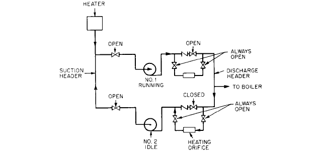
nately, some liquid can be made to flow back from the discharge header through a jumper
line around the check valve into the pump and out into the suction header (Figure 12).
An orifice is provided in this jumper line to regulate the amount of warm-up flow. Care
must be exercised in such an installation to maintain the suction valve open (unless the
warm-up line valve is closed, as when the pump is to be dismantled) lest the entire pump,
suction valve, and suction piping be subjected to full discharge pressure.
The manufacturer’s recommendations should be sought in all cases as to the best
means of providing an adequate warm-up procedure. Care must be taken to ensure that
the pump is warmed uniformly. Stratification of the warm-up flow, or inadequate warm-
up flow volume, can result in casing distortion or rotor bowing, or both.
4
RELIEF VALVES Positive displacement pumps, such as rotary and reciprocating pumps, can
develop discharge pressures much in excess of their maximum design pressures. To pro-
tect these pumps against excessive pressures when the discharge is throttled or shut off,
a pressure relief valve might be used. Some pumps are provided with internal integral
relief valves, but unless operation against a closed discharge is both infrequent and of very
12.12 CHAPTER TWELVE
FIGURE 12 Arrangement for warm-up through jumper line around discharge check valve
short duration, a relief valve with an external return connection must be used and the
liquid from the relief valve must be piped back to the source of supply.
Surge Chambers Generally, centrifugal pumps do not require surge chambers in their
suction or discharge piping. Reciprocating pumps may have a suction and discharge pip-
ing layout that does not require compensation for variations in the flow velocity in the
piping system. In many cases, however, reciprocating pump installations require surge
chambers when the suction or discharge lines are of considerable length, when there is
an appreciable static head on the discharge, when the liquid pumped is hot, or when it is
desirable to smooth out variations in the discharge flow. The type, size, and arrangement
of the surge chamber should be chosen on the basis of the manufacturer’s recommenda-
tions. For more details, see Section 3.4.
Instrumentation There are a number of instruments that are essential to maintaining
a close check on the performance and condition of a pump. A compound pressure gage
should be connected to the suction of the pump, and a pressure gage should be connected
to its discharge at the pressure taps that may be provided in the suction and discharge
flanges. The gages should be mounted in a convenient location so they can be easily
observed.
In addition, it is advisable to provide a flow-metering device. Depending upon the
importance of the installation, indicating meters may be supplemented by recording
attachments.
Whenever pumps incorporate various leakoff arrangements, such as a balancing device
or pressure-reducing labyrinths, a check should be maintained on the quantity of these
leakoffs by measuring orifices and differential gages installed in the leakoff lines.
Pumps operating in important or complex services or operating completely unattended
by remote control may have additional instrumentation, such as speed indicators, vibra-
tion monitors, and bearing or casing temperature indicators. For more detail, see Subsec-
tions 2.3.2, 2.3.3, and Section 3.4.
OPERATION _________________________________________________________
Pumps are generally selected for a given capacity and total head when operating at rated
speed. These characteristics are referred to as “rated conditions of service” and, with few
exceptions, represent those conditions at or near which the pump will operate the great-
est part of the time. Positive displacement pumps cannot operate at any greater flows than
12 INSTALLATION, OPERATION, AND MAINTENANCE 12.13
rated except by increasing their speed, nor can they operate at lower flows except by
reducing their operating speed or bypassing some of the flow back to the source of supply.
(See Section 3.5.)
On the other hand, centrifugal pumps can operate over a wide range of capacities,
from near zero flow to well beyond the rated capacity. Because a centrifugal pump will
always operate at the intersection of its head-capacity and system-head curves, the pump
operating capacity may be altered either by throttling the pump discharge (hence alter-
ing the system-head curve) or by varying the pump speed (changing the pump head-
capacity curve). This makes the centrifugal pump very flexible in a wide range of services
and applications that require the pump to operate at capacities and heads differing con-
siderably from the rated conditions. There are, however, some limitations imposed upon
such operation by hydraulic, mechanical, or thermodynamic considerations (Subsection
2.3.1).
Operation of Centrifugal Pumps at Reduced Flows There are certain minimum
operating flows that must be imposed on centrifugal pumps for either hydraulic or
mechanical reasons. Four limiting factors must be considered: radial thrust, temperature
rise, internal recirculation, and shape of the brake horsepower curve.
Radial thrust is discussed in Subsections 2.2.1 and 2.3.1. For sustained operation, it is
imperative to adhere to the minimum flow limits recommended by the pump manufac-
turer, which depend on the specific design of the pump casing and impeller.
The thermodynamic problem that arises when a centrifugal pump is operated at
extremely reduced flows is caused by the heating up of the liquid handled. The difference
between the brake horsepower consumed and the water horsepower developed repre-
sents the power losses in the pump, except for a small amount lost in the pump bearings.
These power losses are converted to heat and transferred to the liquid passing through
the pump.
If the pump were to operate against a completely closed valve, the power losses would
be equal to the shutoff brake horsepower, and because there would be no flow through the
pump, all this power would go into heating the small quantity of liquid contained in the
pump casing.The pump casing would heat up, and a certain amount of heat would be dis-
sipated by radiation and convection to the atmosphere. However, because the temperature
rise in the liquid pumped could be quite rapid, it is generally safer to ignore the dissipa-
tion of heat through radiation and the absorption of heat by the casing. Calculations for
determining the temperature rise in the pumped liquid are given in Subsection 2.3.1. The
maximum permissible temperature rise in a centrifugal pump varies over a wide range,
depending on the type of service and installation. For hot-water pumps, as on boiler-feed
service, it is generally advisable to limit the temperature rise to about 15°F (8°C).As a gen-
eral rule, the minimum permissible flow to hold the temperature rise in boiler-feed pumps
to this value is 30 gpm for each 100 bhp (9.13 m
3
/h per 100 kW) at shutoff. When the pump
handles cold water, the temperature rise may be permitted to reach 50 or even 100°F (28
or 56°C). The minimum capacity based on thermodynamic considerations is then estab-
lished as the capacity at which the temperature rise is the maximum permitted. Means
and controls used to provide the necessary minimum flows are described in Subsection
2.3.4.
There are also hydraulic considerations that may affect the minimum flow at which a
centrifugal pump can operate. In recent years, correlation has been developed between
operation at low flows and the appearance of hydraulic pulsations both in the suction and
in the discharge of centrifugal impellers. It has been proved that these pulsations are
caused by the development of an internal recirculation at the inlet and discharge of an
impeller at certain flows below the best-efficiency capacity. This subject is treated in Sub-
sections 2.3.1 and 2.3.2. The pump manufacturer’s recommendations on minimum flows
dictated by these considerations must be followed.
Priming With very few exceptions, no centrifugal pump should ever be started until it
is fully primed; that is, until it has been filled with the liquid pumped and all the air con-
tained in the pump has been allowed to escape.The exceptions involve self-priming pumps
12.14 CHAPTER TWELVE
and some special large-capacity, low-head, and low-speed installations where it is not prac-
tical to prime the pump prior to starting; the priming takes place almost simultaneously
with the starting in these cases. For further details, see Section 2.4.
Reciprocating pumps of the piston or plunger type are in principle self-priming. How-
ever, if quick starting is required, priming connections should be piped to a supply above
the pump.
Positive displacement pumps of the rotating type, such as rotary or screw pumps, have
clearances that allow the liquid in the pump to drain back to the suction. When pumping
low-viscosity liquids, the pump may completely dry out when it is idle. In such cases a foot
valve may be used to help keep the pump primed. Alternately, a vacuum device may be
used to prime the pump.When handling liquids of higher viscosity, foot valves are usually
not required because liquid is retained in the clearances and acts as a seal when the pump
is restarted. However, before the initial start of a rotating positive displacement pump,
some of the liquid to be pumped should be introduced through the discharge side of the
pump to wet the rotating element.
The various methods and arrangements used for priming pumps are described in Sec-
tion 2.4.
Final Checks Before Start-Up A few final checks are recommended before a pump is
placed into service for its initial start. For pumps with journal bearings, the bearing covers
should be removed, and the bearings should be flushed and thoroughly cleaned.They should
then be filled with new lubricant in accordance with the manufacturer’s recommendations.
With the coupling disconnected, the driver should be tested again for correct direction
of rotation. Generally an arrow on the pump casing indicates the correct rotation.
It must be possible to rotate the rotor of a centrifugal pump by hand, and in the case
of a pump handling hot liquids, the rotor must be free to rotate with the pump cold or hot.
If the rotor is bound or even drags slightly, do not operate the pump until the cause of the
trouble is determined or corrected.
Starting and Stopping Procedures The steps necessary to start a centrifugal pump
depend upon its type and upon the service on which it is installed. For example, standby
pumps are generally held ready for immediate starting. The suction and discharge gate
valves are held open, and reverse flow through the pump is prevented by the check valve
in the discharge line.
The methods followed in starting are greatly influenced by the shape of the power-
capacity curve of the pump. High- and medium-head pumps (low and medium specific
speeds) have power curves that rise from zero flow to the normal capacity condition. Such
pumps should be started against a closed discharge valve to reduce the starting load on
the driver. A check valve is equivalent to a closed valve for this purpose, as long as another
pump is already on the line. The check valve will not lift until the pump being started
comes up to a speed sufficient to generate a head high enough to lift the check valve from
its seat. If a pump is started with a closed discharge valve, the recirculation bypass line
must be open to prevent overheating.
Low-head pumps (high specific speed) of the mixed-flow and propeller type have power
curves that rise sharply with a reduction in capacity; they should be started with the dis-
charge valve wide open against a check valve, if required, to prevent backflow.
Assuming that the pump in question is motor-driven, that its shutoff power does not
exceed the safe motor power, and that it is to be started against a closed gate valve, the
starting procedure is as follows:
1. Prime the pump, opening the suction valve, closing the drains, and so on, to prepare
the pump for operation.
2. Open the valve in the cooling supply to the bearings, where applicable.
3. Open the valve in the cooling supply if the seal chambers are liquid-cooled.
4. Open the valve in the sealing liquid supply if the pump is so fitted.
12 INSTALLATION, OPERATION, AND MAINTENANCE 12.15
5. Open the warm-up valve of a pump handling hot liquids if the pump is not normally
kept at operating temperature. When the pump is warmed up, close the valve.
6. Open the valve in the recirculating line if the pump should not be operated against
dead shutoff.
7. Start the motor.
8. Open the discharge valve slowly.
9. For pumps equipped with mechanical seals, check for seal leakage: there should be none.
10. For pump with shelf packing, observe the leakage from the stuffing boxes and adjust
the sealing liquid valve for proper flow to ensure the lubrication of the packing. If the
packing is new, do not tighten up on the gland immediately, but let the packing run in
before reducing the leakage through the stuffing boxes.
11. Check the general mechanical operation of the pump and motor.
12. Close the valve in the recirculating line when there is sufficient flow through the
pump to prevent overheating.
If the pump is to be started against a closed check valve with the discharge gate valve
open, the steps are the same, except that the discharge gate valve is opened some time
before the motor is started.
In certain cases, cooling to the bearings and flush liquid to the mechanical seals or to
the packing seal cages is provided by the pump.This, of course, eliminates the need for the
steps listed for the cooling and sealing supply.
Just as in starting a pump, the stopping procedure depends upon the type and service
of the pump. Generally, the steps followed to stop a pump that can operate against a closed
gate valve are
1. Open the valve in the recirculating line.
2. Close the gate valve.
3. Stop the motor.
4. Open the warm-up valve if the pump is to be kept at operating temperature.
5. Close the valve in the cooling supply to the bearings and seal chambers.
6. If the sealing liquid supply is not required while the pump is idle, close the valve in
this supply line.
7. Close the suction valve, open the drain valves, and so on, as required by the particular
installation or if the pump is to be opened up for inspection.
If the pump is of a type that does not permit operation against a closed gate valve, steps
2 and 3 are reversed.
In general, the starting and stopping of steam-turbine-driven pumps require the same
steps and sequence prescribed for a motor-driven pump. As a rule, steam turbines have
various drains and seals that must be opened or closed before and after operation. Simi-
larly, many turbines require warming up before starting. Finally, some turbines require
turning gear operation if they are kept on the line ready to start up. The operator should
therefore follow the steps outlined by the turbine manufacturer in starting and stopping
the turbine.
Most of the steps listed for starting and stopping centrifugal pumps are equally applic-
able to positive displacement pumps. There are, however, two notable exceptions:
1. Never operate a positive displacement pump against a closed discharge. If the gate
valve on the discharge must be closed, always start the pump with the recirculation
bypass valve open.
2. Always open the steam cylinder drain cocks of a steam reciprocating pump before
starting, to allow condensate to escape and to prevent damage to the cylinder heads.