Phadke A.G., Thorp J.S. Synchronized Phasor Measurements and Their Applications
Подождите немного. Документ загружается.

Chapter 5 Phasor Measurement Units and Phasor
Data Concentrators
5.1 Introduction
The history of phasor measurement unit (PMU) evolution was discussed in
Chapter 1. In this chapter we will consider certain practical implementa-
tion aspects of the PMUs and the architecture of the data collection and
management system necessary for efficient utilization of the data provided
by the PMUs. One of the most important features of the PMU technology
is that the measurements are time-stamped with high precision at the
source, so that the data transmission speed is no longer a critical parameter
in making use of this data. All PMU measurements with the same time-
stamp are used to infer the state of the power system at the instant defined
by the time-stamp. It is clear that PMU data could arrive at a central loca-
tion at different times depending upon the propagation delays of the com-
munication channel in use. The time-tags associated with the phasor data
provide an indexing tool which helps create a coherent picture of the
power system out of such data. The Global Positioning System (GPS) has
become the method of choice for providing the time-tags to the PMU
measurements, and will be described briefly in the following sections. Other
aspects of the overall PMU data collection system such as “phasor data con-
centrators” (PDCs), communication systems, etc. will also be considered in
this Chapter.
The industry standards which define file structures for compliant PMUs
have been very important to ensure interoperability of PMUs made by dif-
ferent manufacturers, and will be considered in section 5.6.
5.2 A generic PMU
The PMUs manufactured by different manufacturers differ from each other
in many important aspects. It is therefore difficult to discuss the PMU
hardware configuration in a way which is universally applicable. However,
A.G. Phadke, J.S. Thorp, Synchronized Phasor Measurements and Their Applications,
DOI: 10.1007/978-0-387-76537-2_5, © Springer Science+Business Media, LLC 2008
94 Chapter 5 Phasor Measurement Units and Phasor Data Concentrators
it is possible to discuss a generic PMU, which will capture the essence of
its principal components.
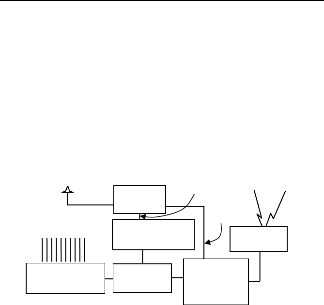
Figure 5.1 is based upon the configuration of the first PMUs built at
Virginia Tech (and shown in Figure 1.1). Remember that PMUs evolved
out of the development of the “symmetrical component distance relay”.
Consequently the structure shown in Figure 5.1 parallels that of a com-
puter relay. The analog inputs are currents and voltages obtained from the
secondary windings of the current and voltage transformers. All three-
phase currents and voltages are used so that positive-sequence measure-
ment can be carried out. In contrast to a relay, a PMU may have currents in
several feeders originating in the substation and voltages belonging to
various buses in the substation.
Fig. 5.1 Major elements of the modern PMU. All elements of the PMU with the
exception of the GPS receiver are to be found in computer relays as well.
The current and voltage signals are converted to voltages with appropri-
ate shunts or instrument transformers (typically within the range of ±10
volts) so that they are matched with the requirements of the analog-to-
digital converters. The sampling rate chosen for the sampling process dic-
tates the frequency response of the anti-aliasing filters. In most cases these
are analog-type filters with a cut-off frequency less than half the sampling
frequency in order to satisfy the Nyquist criterion. As in many relay de-
signs [1] one may use a high sampling rate (called oversampling) with cor-
responding high cut-off frequency of the analog anti-aliasing filters. This
step is then followed by a digital ‘decimation filter’ which converts the sam-
pled data to a lower sampling rate, thus providing a ‘digital anti-aliasing fil-
ter’ concatenated with the analog anti-aliasing filters. The advantage of such
a scheme is that the effective anti-aliasing filters made up of an analog
front end and a digital decimation filter are far more stable as far as aging
Anti-aliasing
filters
A/D conv.
GPS
receiver
Phase-locked
oscillator
Analog
Inputs
Phaso
r
m
icro-
p
rocesso
r
Modem
One pulse
per second
Second Of
Century
Counter

5.3 The global positioning system 95
and temperature variations are concerned. This ensures that all the analog
signals have the same phase shift and attenuation, thus assuring that the
phase angle differences and relative magnitudes of the different signals are
unchanged.
As an added benefit of the oversampling technique, if there is a possibil-
ity of storing raw data from samples of the analog signals, they can be of
great utility as high-bandwidth “digital fault recorders”.
The sampling clock is phase-locked with the GPS clock pulse (to be de-
scribed in the following section). Sampling rates have been going up stead-
ily over the years – starting with a rate of 12 samples per cycle of the
nominal power frequency in the first PMUs to as high as 96 or 128 samples
per cycle in more modern devices, as faster analog-to-digital converters and
microprocessors have become commonplace. Even higher sampling rates are
certainly likely in the future leading to more accurate phasor estimates, since
higher sampling rates do lead to improved estimation accuracy [1].
The microprocessor calculates positive-sequence estimates of all the
current and voltage signals using the techniques described in Chapters 2–4
earlier. Certain other estimates of interest are frequency and rate of change
of frequency measured locally, and these also are included in the output of
the PMU. The time-stamp is created from two of the signals derived from
the GPS receiver. This will be considered in greater detail in the next sec-
tion. For the moment, it is sufficient to say that the time-stamp identifies
the identity of the “universal time coordinated (UTC) second and the in-
stant defining the boundary of one of the power frequency periods as de-
fined in the IEEE standard to be considered in section 5.6 below.
Finally, the principal output of the PMU is the time-stamped measure-
ment to be transferred over the communication links through suitable mo-
dems to a higher level in the measurement system hierarchy. It is the speci-
fication of these output file structures which is the subject of the industry
standard for PMUs to be considered in section 5.6.
5.3 The global positioning system
The GPS was initiated with the launch of the first Block I satellites in 1978
by US Department of Defense.
1
By 1994 the complete constellation of 24
modern satellites was put in place. (In 2007 there are 30 active satellites in
1
There is great wealth of information about the GPS system available in various
technical publications. A highly readable account for the layman is available at the
web-site http://wikipedia.com. There the interested reader will also find links to
other source material.
96 Chapter 5 Phasor Measurement Units and Phasor Data Concentrators
orbit, the extra satellites providing for greater accuracy in estimation of
spatial coordinates of the receivers. Block I and II satellites have been re-
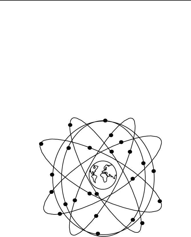
tired.) These are arranged in six orbital planes displaced from each other
by 60° and having an inclination of about 55° with respect to the equatorial
plane (see Figure 5.2). The satellites have an orbital radius of 16,500
miles, and go around the earth twice during one day. They are so arranged
that at least six satellites are visible at most locations on earth, and often as
many as 10 satellites may be available for viewing. The most common use
of the GPS system is in determining the coordinates of the receiver, al-
though for the PMUs the signal which is most important is the one pulse-
per-second. This pulse as received by any receiver on earth is coincident
with all other received pulses to within 1 microsecond. In practice much
better accuracies of synchronization – of the order of a few hundred nano-
seconds – have been realized.
Fig. 5.2 Representation of the GPS satellite disposition. There are four satellites in
each of the six orbits, which orbit around the earth with a period of half a day.
The GPS satellites keep accurate clocks which provide the one pulse-
per-second signal. The time they keep is known as the GPS time which
does not take into account the earth’s rotation. Corrections to the GPS time
are made in the GPS receivers to account for this difference (leap-second
correction) so that the receivers provide UTC clock time. The identity of
the pulse is defined by the number of seconds since the time that the clocks
5.4 Hierarchy for phasor measurement systems 97
began to count (January 6, 1980). It should be noted that the PMU standard
(see section 5.6) uses UNIX time base with a “second-of-century” (SOC)
counter which began counting at midnight on January 1, 1970.
At present there are a number of GPS-like systems being deployed by
other nations, with similar goals. It is expected that the GPS system will
remain the principal source of synchronization for PMUs for the foresee-
able future.
5.4 Hierarchy for phasor measurement systems
The PMUs are installed in power system substations. The selection of sub-
stations where these installations take place depends upon the use to be
made of the measurements they provide. The optimal placement of PMUs
will be considered in some of the following chapters which discuss some
of the applications of phasor measurements.
In most applications, the phasor data is used at locations remote from
the PMUs. Thus an architecture involving PMUs, communication links,
and data concentrators must exist in order to realize the full benefit of the
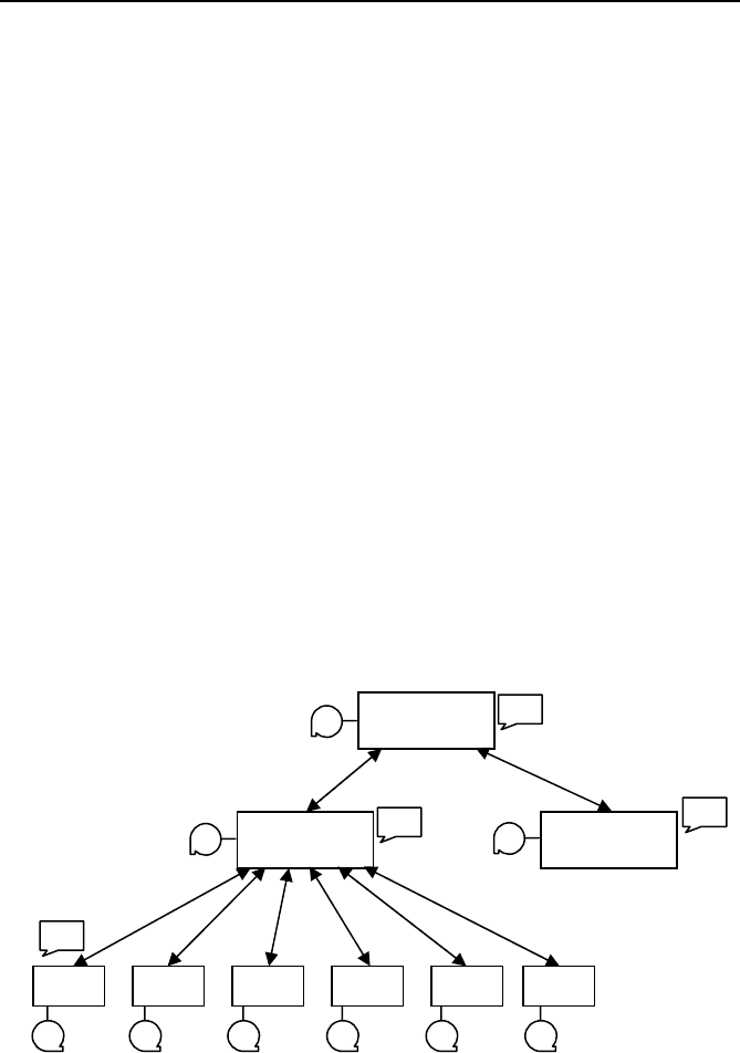
PMU measurement system. A generally accepted architecture of such a
system is shown in Figure 5.3.
Fig. 5.3 Hierarchy of the phasor measurement systems, and levels of phasor data
concentrators.
Super Data
Concentrator
Data
Concentrator
PMU PMU PMU PMU PMU PMU
Data
Concentrator
PMUs located in substations
Data storage
Applications

98 Chapter 5 Phasor Measurement Units and Phasor Data Concentrators
In Figure 5.3 the PMUs are situated in power system substations, and
provide measurements of time-stamped positive-sequence voltages and
currents of all monitored buses and feeders (as well as frequency and rate
of change of frequency). The measurements are stored in local data storage
devices, which can be accessed from remote locations for post-mortem or
diagnostic purposes. The local storage capacity is necessarily limited, and
the stored data belonging to an interesting power system event must be
flagged for permanent storage so that it is not overwritten when the local
storage capacity is exhausted. The phasor data is also available for real-
time applications in a steady stream as soon as the measurements are
made. There may well be some local application tasks which require PMU
data, in which case it can be made available locally for such tasks. How-
ever, the main use of the real-time data is at a higher level where data from
several PMUs is available.
The devices at next level of the hierarchy are commonly known as
“phasor data concentrators” (PDCs). Typical function of the PDCs is to
gather data from several PMUs, reject bad data, align the time–stamps, and
create a coherent record of simultaneously recorded data from a wider part
of the power system. There are local storage facilities in the PDCs, as well
as application functions which need the PMU data available at the PDC.
This can be made available by the PDCs to the local applications in real
time. (Clearly, the communication and data management delays at the
PDCs will create greater latency in the real-time data, but all practical
experience shows that this is not unmanageable. The question of data la-
tency will be further considered when applications are discussed in later
chapters.)
One may view the first hierarchical level of PDCs as being regional in
their data-gathering capability. On a systemwide scale, one must contem-
plate another level of the hierarchy (Super Data Concentrator in Figure
5.3). The functions at this level are similar to those at the PDC levels –
that is, there is facility for data storage of data aligned with time-tags (at a
somewhat increased data latency), as well as a steady stream of near real-
time data for applications which require data over the entire system.
Figure 5.3 shows the communication links to be bidirectional. Indeed,
most of the data flow is upward in the hierarchy, although there are some
tasks which require communication capability in the reverse direction.
Usually these are commands for configuring the downstream components,
requesting data in a particular form, etc. In general, the capacity for
downward communication is not as demanding as one in the upward direc-
tion. These issues will be considered in Section 5.6 where the prevailing
industry standard for PMUs [2] will be discussed.

5.5 Communication options for PMUs 99
5.5 Communication options for PMUs
Communication facilities are essential for applications requiring phasor data
at remote locations. Two aspects of data transfer are significant in any com-
munication task [3, 4]. Channel capacity is the measure of the data rate (in
kilobits per second or megabits per second) that can be sustained on the
available data link. The second aspect is the latency, defined as the time lag
between the time at which the data is created and when it is available for the
desired application. The data volume created by the PMUs is quite modest,
so that channel capacity is rarely a limiting factor in most applications. On
the other hand, some applications may require relatively small latency – in
particular, applications for real-time control of power systems. At the other
extreme are post-mortem analysis applications, which require PMU data to
help analyze the power system performance during major disturbances. These
applications are not affected by large delays in transferring the data. Several
applications of PMU data will be considered in the following chapters.
The communication options available for PMU data transfer may be
classified according to the physical medium used for communication [5].
Leased telephone circuits were among the first communication media used
for these purposes. Switched telephone circuits can be used when data
transfer latency is not of importance. More common electric utility commu-
nication media such as “power line carrier” and microwave links have also
been used, and continue to be used in many current applications. Of course,
the medium of choice now is fiber-optic links which have unsurpassed
channel capacity, high data transfer rates, and immunity to electromagnetic
interference. Figure 5.4 [5] shows typical construction of a fiber-optic cable
Fig. 5.4 Typical fiber optic cable construction. Such cables are in wide use on
electric utility systems.
Galvanized steel rods
Plastic tubes
Plastic jacket
Aluminum alloy tube
Kevlar strength members
Fibers
100 Chapter 5 Phasor Measurement Units and Phasor Data Concentrators
commonly used in electric utility industry. The most popular deployment
of fiber-optic cables is in the ground wires of transmission lines. The
ground wires may carry multiple fibers which may be used for other com-
munication, protection, and control applications for power system opera-
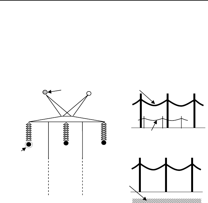
tion and management. Other configurations of fiber-optic links may in-
volve separate towers for the fiber cable in the electric utility right-of-way,
wrapping the fiber cable around the phase conductors, or direct burying the
fiber cable in the ground (see Figure 5.5).
Fig. 5.5 Arrangement of fiber-optic bundle commonly employed by electric utili-
ties. (a) The fiber is in the ground wire. (b) The fiber bundle is strung on separate
towers on transmission line right-of-way. (c) The fiber-optic cable is direct-buried.
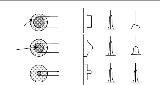
The technology of fiber-optics is changing very rapidly [6]. Fibers may
be single-mode (meaning that the entire fiber cross-section is homogene-
ous material) or multimode with graded index or step-index change in the
refractive index of the fiber and the cladding material (see Figure 5.6).
Multimode fibers tend to have greater loss per km, because of the partial
loss of energy due to refraction at the boundary between the fiber core and
the cladding. Single-mode fibers propagate optical waves along the axis of
the fiber, and have minimal loss during transmission. The wavelength of
light used in these systems ranges from 900 nm to 1800 nm. Typical loss
in the fibers may range from 0.5 db per km (single-mode fibers) to 4 db
per km (multimode fibers). In addition, loss in the connectors and repeaters
Fiber bundle wrapped around
Phase conductor
(a)
(b)
(c)
Fiber bundle in ground wire
Fiber bundle
direct-buried
Fiber bundle on
separate towers
Power line
Transmission
Tower
5.5 Communication options for PMUs 101
Fig. 5.6 Types of fibers used in fiber-optic communication, their relative dimen-
sions, and modes of transmission.
must also be taken into account. Depending upon the length of transmis-
sion path and allowed transmission loss-budget, an appropriate type of fi-
ber is selected for a given application.
One may also classify the communication facilities based upon the
communication protocols in use. Here also the field is rapidly changing,
and it is only possible to mention a few of the available protocols which
have been used in phasor measurement applications. The IEEE standard
applicable to PMU technology [2] discusses the general requirements for
communications with PMUs in Annexe I of the standard. When serial
communication over an RS-232 is used the entire data stream from the
PMU (as defined in the PMU Standard and discussed more fully in the
next section) is to be mapped in proper order on to the serial communica-
tion port. The communication system may apply any protocol, encryption,
or change the ordering of the data, as long as it is restored to its original
format at the receiver end.
PMU messages may also be mapped in their entity into transmission
control protocol (TCP) [7] or user datagram protocol (UDP) [8], and will
be accessed by using standard Internet Protocol (IP) functions. The (IP)
may be carried over Ethernet or other available transport means.
In recent years IEC Standard 61850 has been introduced to facilitate
electric utility substation automation including protection and control [9].
In its present version, this standard has not been identified as being useable
Single mode fiber
Graded index fiber
Step index fiber
~ 200
μ
m
cladding
~ 50-100
μ
m
core
~ 10
μ
m
Index of
Refraction
Input
pulse
Output
pulse
102 Chapter 5 Phasor Measurement Units and Phasor Data Concentrators
for PMUs. It may be that advances in the state-of-the-art in PMU technol-
ogy and substation communication technology will lead to the acceptance
of IEC 61850 by the PMU community.
5.6 Functional requirements of PMUs and PDCs
5.6.1 The evolution of “Synchrophasor” standard
In order to achieve interoperability among PMUs made by different manu-
facturers, it is essential that all PMUs perform to a common standard. Ref-
erence [7] is the current IEEE standard which defines requirements for
compliance.
A short account of the development of this standard may be of interest.
The “Synchrophasor” standard was first issued in 1995 [10]. PMUs of
early manufacture based on this standard were tested for interoperability,
and it was discovered that their performance at off-nominal frequencies
was not identical [11]. From the point of interoperability of equipment, this
was not acceptable. It was soon recognized that the then existing standard
[11] was not very clear on the topic of performance requirements for
PMUs at off-nominal frequencies. A working group of the Power System
Relaying Committee of IEEE undertook the revision of the standard, and
the result is the current standard [2] which clarified the requirements for
PMU response to off-nominal frequency inputs. The requirements for off-
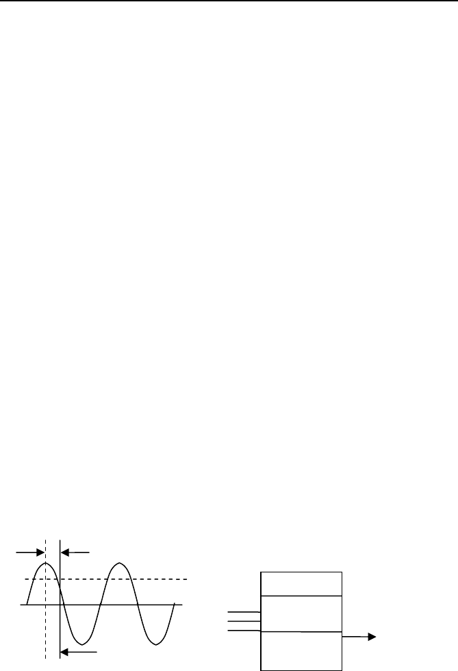
nominal frequencies can be explained with the help of Figure 5.7. As noted
in Chapter 1 the definition of a phasor is independent of its frequency;
thus, if the input signals connected to the PMU are pure sinusoids of any
frequency and the phasor estimate is reported at the time-tag as shown in
Figure 5.7, the output phasor must have a magnitude equal to the rms value
Fig. 5.7 PMU performance requirements for input signals of any frequency. (a)
Input signal connected to the PMU terminals, and (b) the required output phasor
estimate.
PMU
Input
wires
Phasor time-
tag (reporting
instant)
θ
X
rms
Filters
Sampled
Data
Phasor
Estimator
Phasor
X
r
+ j X
i
= X
rms
ε
jθ