NP 100 - Mariners Handbook
Подождите немного. Документ загружается.


CHAPTER 8
180
H.102 (Aug 2004)
HYDROGRAPHIC NOTE
(for instructions, see overleaf)
Date . . . . . . . . . . . . . . . . . . . . . . . . . . . . . . . . . . . . . . . . .
Ref. No. . . . . . . . . . . . . . . . . . . . . . . . . . . . . . . . . . . . . .
Name of ship or sender: . . . . . . . . . . . . . . . . . . . . . . . . . . . . . . . . . . . . . . . . . . . . . . . . . . . . . . . . . . . . . . . . . . . . . . . . . . . . .
Address of sender: . . . . . . . . . . . . . . . . . . . . . . . . . . . . . . . . . . . . . . . . . . . . . . . . . . . . . . . . . . . . . . . . . . . . . . . . . . . . . . . .
. . . . . . . . . . . . . . . . . . . . . . . . . . . . . . . . . . . . . . . . . . . . . . . . . . . . . . . . . . . . . . . . . . . . . . . . . . . . . . . . . . . . . . . . . . . . . . . . . .
. . . . . . . . . . . . . . . . . . . . . . . . . . . . . . . . . . . . . . . . . . . . . . . . . . . . . . . . . . . . . . . . . . . . . . . . . . . . . . . . . . . . . . . . . . . . . . . . . .
Tel/Fax/Telex No./ e-mail address of sender (if appropriate):. . . . . . . . . . . . . . . . . . . . . . . . . . . . . . . . . . . . . . . . . . . . . . . . .
General locality . . . . . . . . . . . . . . . . . . . . . . . . . . . . . . . . . . . . . . . . . . . . . . . . . . . . . . . . . . . . . . . . . . . . . . . . . . . . . . . . . .
Subject . . . . . . . . . . . . . . . . . . . . . . . . . . . . . . . . . . . . . . . . . . . . . . . . . . . . . . . . . . . . . . . . . . . . . . . . . . . . . . . . . . . . . . . . . . .
Position. Lat Long. . . . . . . . . . . . . . . . . . . . . . . . . . . . . . . . . . . . . . . . . . . . . . . . . . . . . . . . . . . . . . . . . . . . . . . . . . . . . . . . . .
British Admiralty Charts affected Edition dated. . . . . . . . . . . . . . . . . . . . . . . . . . . . . . . . . . . . . . . . . . . . . . . . . . . . . . . . . .
Position fixing system used Datum set. . . . . . . . . . . . . . . . . . . . . . . . . . . . . . . . . . . . . . . . . . . . . . . . . . . . . . . . . . . . . . . . . .
Latest Weekly Edition of Notice to Mariners held . . . . . . . . . . . . . . . . . . . . . . . . . . . . . . . . . . . . . . . . . . . . . . . . . . . . . . .
ENCs affected . . . . . . . . . . . . . . . . . . . . . . . . . . . . . . . . . . . . . . . . . . . . . . . . . . . . . . . . . . . . . . . . . . . . . . . . . . . . . . . . . . .
Latest Update disk held, week . . . . . . . . . . . . . . . . . . . . . . . . . . . . . . . . . . . . . . . . . . . . . . . . . . . . . . . . . . . . . . . . . . . . . . . .
Publications affected (Edition No., date of latest supplement, page and Light List No. etc.). . . . . . . . . . . . . . . .
. . . . . . . . . . . . . . . . . . . . . . . . . . . . . . . . . . . . . . . . . . . . . . . . . . . . . . . . . . . . . . . . . . . . . . . . . . . . . . . . . . . . . . . . . . . . . . . . . .
Details:−−
A replacement copy of Chart No is required, but see 4 overleaf.. . . . . . . . . . . . . . . . . . . . . . . . . . . . . . . . . . . . . .
Signature of observer/reporter . . . . . . . . . . . . . . . . . . . . . . . . . . . . . . . . . . . . . . . . . . . . . . . . . . . . . . . . . . . . .
Home
Contents
Index

CHAPTER 8
181
HYDROGRAPHIC NOTE
Forwarding information for British Admiralty Charts and
Hydrographic Publications
INSTRUCTIONS:
1. Mariners are requested to notify the United Kingdom Hydrographic Office, Admiralty Way, Taunton, Somerset, TA1 2DN, United
Kingdom, when new or suspected dangers to navigation are discovered, changes observed in aids to navigation, or corrections to
publications are seen to be necessary. The Mariner’s Handbook (NP 100) Chapter 8 gives general instructions. If practicable the
Mariner should contact the originating hydrographic office when navigating on non-UKHO ENCs. The provisions of international and
national laws should be complied with when forwarding such reports.
2. This form and its instructions have been designed to help both the sender and the recipient. It should be used, or followed closely,
whenever appropriate.
Copies of this Form may be obtained gratis from the United Kingdom Hydrographic Office at the above address or principal Chart
Agents (see Annual Notice to Mariners No. 2).
3. When a position is defined by sextant angles or bearings (true or magnetic being specified) more than two should be used in order to
provide a check. Distances observed by radar and the raw readings of the navigation system in use, should be quoted wherever
possible.
Latitude and longitude should only be used specifically to position the details when they have been fixed by astronomical observations
or GPS and a full description of the method, equipment and datum (where applicable) used should be given.
4. Paper charts: A cutting from the largest scale chart is the best medium for forwarding details, the alterations and additions being shown
thereon in red. When requested, a new copy will be sent in replacement of a chart that has been used to forward information, or when
extensive observations have involved defacement of the observer’s chart. If it is preferred to show the amendments on a tracing of the
largest scale chart (rather than on the chart itself) these should be in red as above, but adequate details from the chart must be traced in
black ink to enable the amendments to be fitted correctly.
ENCs: A screen dump of the largest scale usage band ENC with the alterations and additions being shown thereon in red.
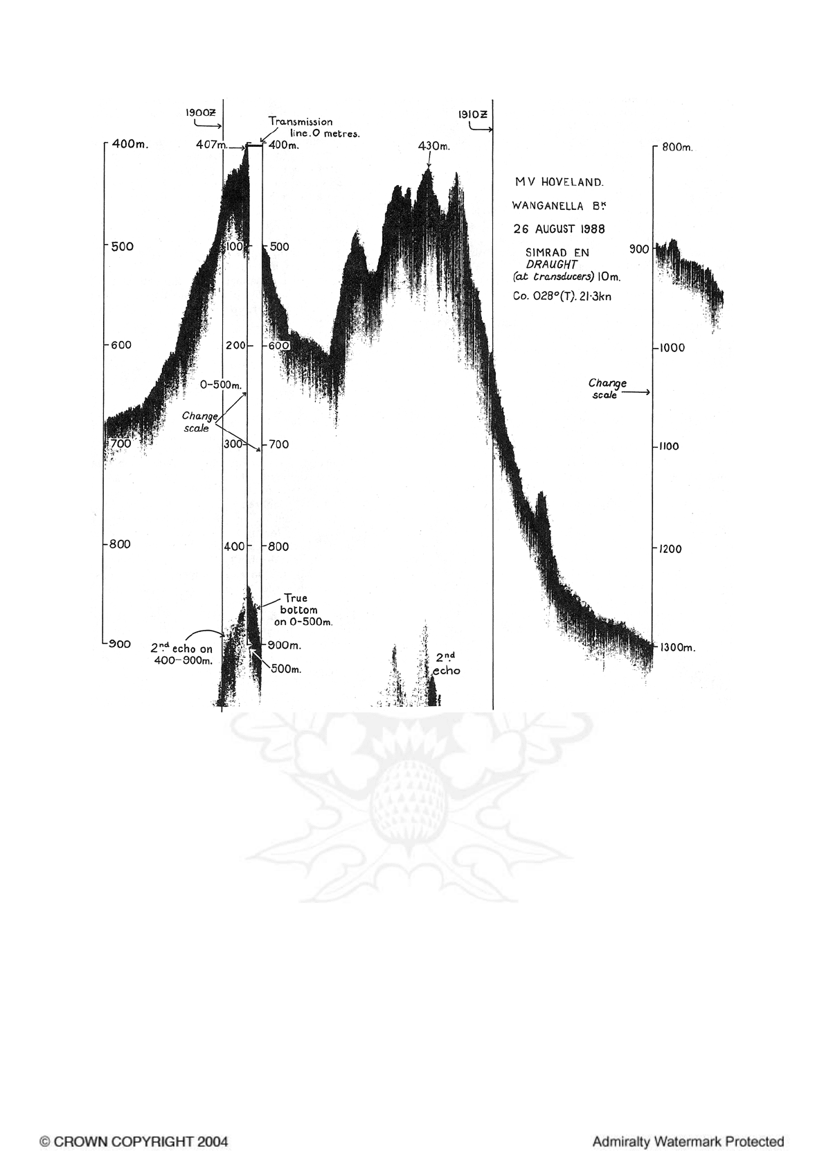
5. When soundings are obtained The Mariner’s Handbook (NP 100) should be consulted. The echo sounding trace should be marked
with times, depths, etc., and forwarded with the report. It is important to state whether the echo sounder is set to register depths below
the surface or below the keel; in the latter case the vessel’s draught should be given. Time and date should be given in order that
corrections for the height of the tide may be made where necessary. The make, name and type of set should also be given.
6. Modern echo sounders frequently record signals from echoes received back after one or more rotations of the stylus have been
completed. Thus with a set whose maximum range is 500m, an echo recorded at 50m may be from depths of 50m, 550m or even
1050m. Soundings recorded beyond the set’s nominal range can usually be recognised by the following:
(a) the trace being weaker than normal for the depth recorded,
(b) the trace passing through the transmission line,
(c) the feathery nature of the trace.
As a check that apparently shoal soundings are not due to echoes received beyond the set’s nominal range, soundings should be
continued until reasonable agreement with charted soundings is reached. However, soundings received after one or more rotations of
the stylus can still be useful and should be submitted if they show significant differences from charted depths.
7. Reports which cannot be confirmed or are lacking in certain details should not be withheld. Shortcomings should be stressed and any
firm expectation of being able to check the information on a succeeding voyage should be mentioned.
8. Reports of shoal soundings, uncharted dangers and navigational aids out of order should, at the mariner’s discretion, also be made by
radio to the nearest coast radio station. The draught of modern tankers is such that any uncharted depth under 30 metres or 15 fathoms
may be of sufficient importance to justify a radio message.
9. Port information should be forwarded on Form H.102a together with Form H.102. Form H.102a lists the information required for
Admiralty Sailing Directions and should be used as an aide memoire. Where there is insufficient space on the form an additional sheet
should be used.
10. Reports on ocean currents should be made in accordance with The Mariner’s Handbook.
Note. An acknowledgement or receipt will be sent and the information then used to the best advantage which may mean immediate
action or inclusion in a revision in due course. When a Notice to Mariners is issued, the sender’s ship or name is quoted as authority
unless (as sometimes happens) the information is also received from other authorities. An explanation of the use made of contributions
from all parts of the world would be too great a task and a further communication should only be expected when the information is of
outstanding value or has unusual features.
Home
Contents
Index

CHAPTER 8
182
Positions
Charts
8.6
1 The largest scale chart available, a plotting sheet
prepared to a suitable scale, or, for oceanic soundings, an
ocean plotting sheet (1.23), should be used to plot the
ship’s position during observations.
2 A cutting from a chart, with the alterations or additions
shown in red, is often the best way of forwarding detail. If
required, a replacement for a chart used for forwarding
information will be supplied gratis. If it is preferred to
show the amendments on a tracing of the chart, rather than
on the chart itself, they should be shown in red, but
adequate detail from the chart must be traced in black to
enable the tracing to be fitted correctly.
3 The chart used should be stated and described as at
1.52.
8.7
1 Geographical positions. Latitude and longitude should
only be used specifically to position details when they have
been fixed by astronomical observations or by a
position-fixing system which reads out in latitude and
longitude.
8.8
1 Astronomical positions. Observations should be
accompanied by the names and altitudes of the heavenly
bodies, and the times of the observations. A note of any
corrections not already applied, and an estimate of any
probable error due to conditions prevailing at the time,
should also be included.
8.9
1 Visual fixes. To ensure the greatest accuracy, a fix
defined by horizontal sextant angles, compass bearings (true
or magnetic being specified), or ranges, should consist if
possible of more than two observations. The observations
should be taken as nearly as possible simultaneously,
should be carefully recorded at the time and listed in the
report with any corrections that have been applied to them.
8.10
1 Positions from Electronic position-fixing systems.
Loran-C positions should be accompanied by the time and
full details of the fixes obtained. It should also be stated
whether any corrections have been applied, and if so their
values.
8.11
1 GPS positions. The report should include information on
whether the receiver was set to WGS84 Datum or was
outputting positions referred to another datum, or whether
any position shifts quoted on the chart have been applied.
Non essential extra information can be included such as the
receiver model, PDOP, HDOP or GDOP values (indications
of theoretical quality of position fixing depending upon the
distribution of satellites).
2 Mariners are requested to report observed differences
between positions referenced to chart graticule and those
from GPS, referenced to WGS84 Datum, using Form
H.102b (Form for Recording GPS Observations and
Corresponding Chart Positions). This form is available from
HDC (Geodesy) at the UKHO. The results of these
observations are examined and may provide evidence for
notes detailing approximate differences between WGS84
Datum and the datum of the chart.
8.12
1 Channels and passages. When information is reported
about one shore of a channel or passage, or of an island in
one, every endeavour should be made to obtain a
connection between the two shores by angles, bearings or
ranges.
Soundings
Sounder
8.13
1 The following information about the sounder should be
included in the report.
Make, name and type of set;
The number of revolutions per minute of the stylus
(checked by stop-watch).
Speed of sound in sea water in metres or fathoms per
second equivalent to the stylus speed.
2 Whether soundings have been corrected from
Echo-sounding Correction Tables (NP 139).
Setting of the scale zero. That is whether depths
recorded are from the sea surface or from the
underside of the keel. If from the keel, the ship’s
draught abreast the transducers at the time and the
height of the transducers above the keel should be
given.
3 Where the displacement of the transducers from the
fixing position is appreciable, the amount of this
displacement and whether allowance has been
made for it.
For methods of checking the accuracy of a sounder, see
2.97—2.99.
Trace
8.14
1 With the report, the trace should be forwarded. To be
used to full advantage, it should be marked as follows.
A line drawn across it each time a fix is taken, and
at regular time intervals.
The times of each fix and alteration of course
inserted, and times of interval marks at not more
than 15 minute intervals.
2 The position of each fix and other recorded events
inserted where possible, unless a GPS printout or
separate list of times and corresponding positions
is enclosed with the report.
The recorded depths of all peak soundings inserted.
The limits of the phase or scale range in which the
set is running marked, noting particularly when a
change is made.
3 Name of the ship, date, zone time used and scale
reading of the shoalest edge of the transmission
line should be marked on the trace.
Diagram 8.14 shows a specimen trace with all the
information required.
Investigations
8.15
1 In oceanic areas, when nearing a feature over which the
depth is within the range of the ship’s echo sounder, but
which is approached in depths greater than that range, it is
best after starting the sounder in the shoalest range scale, to
increase the range and leave it set to the maximum range
scale until the bottom echo appears, and then to change
scale as the depth decreases.
2 Whenever depths are found that are at variance with
charted depths, the value of the report will be much
enhanced by continuing to run the sounder until reasonable,
or even approximate, agreement with the chart is reached.
This will disclose shoal depths which are “round the clock”
(2.100) or similar false echoes. However, such false echoes
can still be useful if they show significant differences from
charted depths, and should be submitted.
Home
Contents
Index
CHAPTER 8
183
Marked-up trace (8.14)
3 If an unexpected shoal or seamount is encountered,
every endeavour should be made to run back over the same
ground on a reciprocal course to get a further sounding
with, if possible, an accurate fix of its position. If more
time can be spared, several lines of soundings across the
shoal area would make an even more useful report.
Particularly so if the least depth over the shoal is obtained
and the limits of the shoal area defined.
4 Care should be taken however not to hazard the ship
when attempting to delineate a newly-discovered shoal. In
oceanic areas, soundings may give little warning of the
presence of a dangerous pinnacle, see 2.14
Sandwaves
8.16
1 For remarks on sounding over areas of sandwaves, see
4.59—4.60.
Charting of reported shoals
8.17
1 When reports of shoals are received in the Hydrographic
Office they are carefully considered in the light of
accompanying or other evidence before any action is taken
to amend the charts. In the past much time and effort has
been wasted searching for non-existent shoals. When
unexpected shoal soundings are obtained in waters where
the chart gives no indication of them, even though
discoloured water may be seen, the only certain method of
confirming their existence is by taking a cast of the lead.
2 Where, however, the charted depth is nowhere more than
the scale reading of the set and the shoal is seen to rise
from the bottom on the trace, provided the speed and
setting of the set is correct, the shoal sounding is usually
accepted unconditionally.
Navigational marks
Lights
8.18
1 The simplest way to ensure a full report on lights is to
follow the columns in the Light List, giving the information
required under each heading. Some details may have to be
omitted for lack of data whilst others it may be possible to
amplify. Characteristics should be checked with a
stop-watch.
Home
Contents
Index

CHAPTER 8
184
Buoys
8.19
1 Details of buoys shown on the largest scale chart and
given in Sailing Directions should be verified. The position
of a buoy should be checked, where possible, by fixing the
ship and taking a range and bearing to the buoy, or by
another suitable method.
Beacons and daymarks
8.20
1 New marks should be fixed from seaward, and the
position verified where possible by responsible authorities
in the area, who should be quoted in the report.
Conspicuous objects
8.21
1 Reports on conspicuous objects are required frequently
since objects which were once conspicuous may later be
obscured by trees, or made less conspicuous by new
buildings or other developments. The positions of
conspicuous objects can sometimes be obtained from local
authorities, but more often must be fixed, like the new
marks above, from seaward.
Wrecks
8.22
1 Stranded wrecks (which are wrecks any part of whose
hull dries) or wrecks which dry should be fixed by the best
available method and details recorded. The measured or
estimated height of a wreck above water, or the amount
which it dries, should be noted. The direction of heading
and the extremities of large wrecks should be fixed if the
scale of the chart is sufficiently large.
Tidal streams
Reporting
8.23
1 Reports of unexpected tidal streams should be obtained
wherever possible. If only a general description of the
direction can be given, it is preferable to use terms such as
“east-going” and “west-going”, rather than “flood” and
“ebb” streams which can be ambiguous.
2 The time of the change of stream should always be
referred to the time of local high water, or if this in not
known, to the time of high water at the nearest port for
which predictions are given in Admiralty Tide Tables.
Port facilities
General information
8.24
1 Form H.102a is designed as an aide-memoire for
checking and collecting port information, and for rendering
with Form H.102.
2 When opportunity occurs, Sailing Directions should be
checked for inaccuracies, out-of-date information and
omissions. Port regulations, pilotage, berthing provisions
and water and other facilities are frequently subject to
change. It is often only by reports from visitors that charts
and publications can be kept up-to-date for such
information. The value of such reports is enhanced if they
can be accompanied by the local Port Handbook or a point
of contact for further information.
3 When dredging operations or building work, such as that
on breakwaters, wharves, docks and reclamations are
described, a clear distinction should be made between work
completed, work in progress, and work projected. An
approximate date for the completion of unfinished or
projected work is valuable.
4 Though all dimensions of piers or wharves are useful,
the depths at the outer end and alongside are the most
important items.
Where dredged channels exist, the date of the last
dredging and the depth obtained should be reported if
found to be different from those charted.
Offshore reports
Ocean currents
8.25
1 Much useful knowledge of ocean currents (4.17—4.29)
can be obtained by ships on passage. Form H.568 — Sea
Surface Current Observations is designed for the collection
of such information and is obtainable gratis from the
Hydrographic Office, or through any Admiralty Chart
Agent.
2 Instructions for rendering the form, which are carried on
it, call mainly for a record of courses and distances run
through the water, together with accurate observations of
the wind to enable this component of the ship’s drift to be
eliminated in analysis, and sea surface temperature readings
to enable the observed current to be related to different
water masses.
3 Though primarily intended for reporting unexpected
currents, the form can usefully be maintained on a routine
basis for all passages outside coastal waters to give
valuable information regarding predicted currents.
Discoloured water
8.26
1 The legend “discoloured water” (see 4.46) appears on
many charts, particularly those of the Pacific Ocean where
shoals rise with alarming abruptness from great depths.
Most of these legends remain on the charts from the last
century when very few deep sea soundings were available,
and less was known of the causes of discoloured water.
Only a few of the reports of discoloured water have proved
on examination to be caused by shoals.
2 Today, such reports can be compared with the
accumulated information for the area concerned, a more
thorough assessment made, and as a result this legend is
now seldom inserted on charts.
3 Mariners are therefore encouraged, whilst having due
regard to the safety of their vessels, to approach sightings
of discoloured water to find whether or not the
discoloration is due to shoaling.
4 If there is good reason to suppose the discoloration is
due to shoal water, a hydrographic note, accompanied by
an echo sounder trace and any other supporting evidence,
should be rendered. If there is no indication of a shoal, a
report should be forwarded to the Meteorological Office,
Exeter, Devon EX1 3PB and a copy sent to the
Hydrographic Office.
Home
Contents
Index

CHAPTER 8
185
H.102a (April 1990)
HYDROGRAPHIC NOTE FOR PORT
INFORMATION
(To accompany Form H.102)
Name of ship or sender: . . . . . . . . . . . . . . . . . . . . . . . . . . . . . . . . . . . . . . . . . . . . . . . . . . . . . . . . . . . . . . . . . . . . . . . . . . . . . . . .
Address: Ref. No.. . . . . . . . . . . . . . . . . . . . . . . . . . . . . . . . . . . . . . . . . . . . . . . . . . . . . . . . . . . . . . . . . . . . . . . .
Date: . . . . . . . . . . . . . . . . . . . . . . . . . . . . . . . . . . . . . . . . . . . . . . . . . . . . . . . . . . . . . . . . . . . . . . . . . . . . . . . . . .
. . . . . . . . . . . . . . . . . . . . . . . . . . . . . . . . . . . . . . . . . . . . . . .
1. NAME OF PORT
2. GENERAL REMARKS
Principal activities and trade.
Latest population figures and date.
Number of ships or tonnage
handled per year.
Maximum size of vessel handled.
Copy of Port Handbook
if available.
3. ANCHORAGES
Designation, depths, holding ground,
shelter afforded.
4. PILOTAGE
Authority for requests.
Embarkation position.
Regulations.
5. DIRECTIONS
Entry and berthing information.
Tidal Streams.
Navigational aids.
6. TUGS
Number available and
max. hp.
7. WHARVES
Names, numbers or positions.
Lengths.
Depths alongside.
Heights above Chart Datum.
Facilities available.
8. CARGO HANDLING
Containers, lighters,
Ro-Ro etc.
Home
Contents
Index

CHAPTER 8
186
9. CRANES
Brief details and
max. capacity.
10. REPAIRS
Hull, machinery and
underwater.
Ship and boat yards.
Docking or slipping
facilities.
Give size of vessels
handled or dimensions.
Hards and ramps.
Divers.
11. RESCUE AND DISTRESS
Salvage, lifeboat,
Coastguard, etc.
12. SUPPLIES
Fuel with type and quantities
available.
Fresh water with rate
of supply.
Provisions.
13. SERVICES
Medical.
De-ratting.
Consuls.
Ship chandlery,
compass adjustment,
tank cleaning,
hull painting.
14. COMMUNICATIONS
Road, rail and air
services available.
Nearest airport or airfield.
Port radio and information
service with frequencies
and hours of operating.
15. PORT AUTHORITY
Designation, address
and telephone number.
16. SMALL CRAFT FACILITIES
Information and facilities
for small craft (eg yachts)
visiting the port.
Yacht Clubs, berths, etc.
17 VIEWS
Photographs (where permitted)
of the approaches, leading
marks, the entrance to the
harbour, etc.
Picture postcards may also
be useful.
Signature of observer/reporter . . . . . . . . . . . . . . . . . . . . . . . . . . . . . . . . . . . . . . . . . . . . . . . . . . . . . . . . . . . . . . . . .
Home
Contents
Index

CHAPTER 8
187
Bioluminescence
8.27
1 Forms of bioluminescence are discussed at 4.47—4.48.
Details required in reports are as follows:
Name of vessel and observer
Date, time and period of day (for example; early
evening, night, or dawn.)
Position of sighting
Colour of phenomenon
Description of phenomenon
Approximate extent of phenomenon
Means of stimulation (if any)
2 Reports should be rendered to the United Kingdom
Hydrographic Office whenever possible. They can be
submitted on a Marine Bioluminescence Observations
Reporting Form (H.636), available from the Royal Navy
Technical Author at the UKHO, or made as a standard
Hydrographic Note (H.102).
Underwater volcanoes and earthquakes
8.28
1 When tremors or shocks attributable to underwater
volcanoes and earthquakes or (4.39—4.40) are experienced,
reports made to the United Kingdom Hydrographic Office,
on Form H.102 or by radio, are of considerable value.
Reports should give a brief description of the
occurrence, its time and date, the ship’s position, and the
depth of water at that position.
Whales
8.29
1 Given the importance of cetacean conservation, reports
of whales, porpoises and dolphins are of considerable
interest.
For identifying species, useful publications are Guide to
the Identification of Whales, Dolphins and Porpoises in
European Seas (by P G H Evans) and Whales, Dolphins
and Porpoises — The visual guide to all the world’s
cetaceans (by M Carwardine).
2 Details required in reports are as follows:
Name of vessel and observer
Date, time and period of day (for example; early
evening, night, or dawn.)
Position of sighting
Identification and supportive description
Number sighted
3 Reports should be rendered to the United Kingdom
Hydrographic Office whenever possible. They can be
submitted on a Marine Life Reporting Form (H.637),
available from the Maritime Environment Information
Centre of the UKHO, or made as a standard Hydrographic
Note (H.102).
Turtles in British waters
8.30
1 Reports detailing sightings of turtles are of considerable
interest. For identifying species, a useful publication is The
Turtle Code (by Scottish Natural Heritage).
Reports should be made and forwarded in the same way
as those described above for whales.
Ornithology
8.31
1 Those interested in ornithology can often make useful
additions to the existing knowledge of bird behaviour and
migration; details required can be obtained from the Hon
Secretary, RN Birdwatching Society, 19 Downland Way,
South Wonston, Winchester, Hants SO21 3HS.
Magnetic variation
Reporting
8.32
1 In many parts of the world there is a continuous need
for more data for the plotting of isogonic curves on
Admiralty Magnetic Variation charts.
All observations are valuable, but there is a particular
requirement for data S of latitude 40°S, or in areas where
the isogonic curves are close together, or where there are
local magnetic anomalies (4.62).
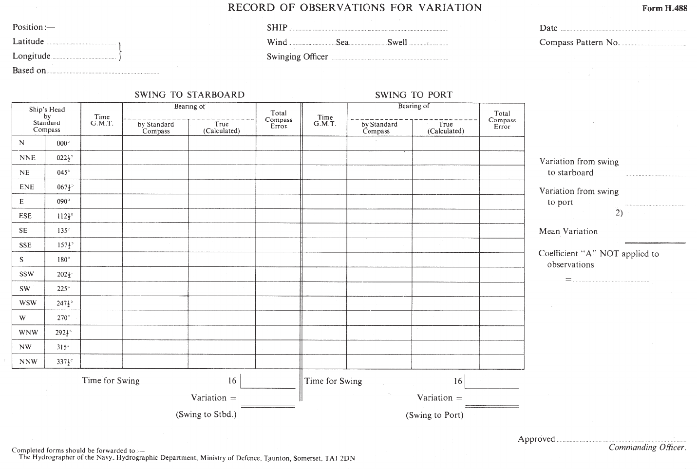
2 Form H.488 — Record of Observations for Variation
(page 188) which can be obtained from the Hydrographic
Office, is designed for rendering the observations. The
method to be used for making the observations is described
on the back of the form.
Local magnetic anomalies
Reporting
8.33
1 Whenever a ship passes over a local magnetic anomaly
(4.62), the position, extent of the anomaly, and the amount
and direction of the deflection of the compass needle,
should be reported, or confirmed if it is already charted, on
Form H.102 to the United Kingdom National Hydrographer.
VIEWS
Introduction
8.34
1 The general availability of modern aids to navigation has
reduced the need for long-range coastal views for landfalls
and coastal passages, although this remains just as
important for vessels not fitted with an
electronic-position-fixing system. However, the need to
change from instrument to visual navigation still occurs at
some stage for all mariners, and for this change good
views are still invaluable for the quick recognition of
features.
2 New photographs should be obtained where views
published in Admiralty Sailing Directions or on Admiralty
charts are out-of-date or inadequate, or where a new view
would help the mariner, if circumstances permit and
national regulations do not prohibit.
3 The following description aims to rationalise the
requirement for views and to set out the manner in which
new data should be produced in order to give the best
assistance both to the chart compiler and to the mariner.
4 When it is not possible to comply with the exact
requirements, it is extremely important to bear in mind that
even an imperfect photograph, correctly annotated, can
often be used to produce a view of considerable help to the
mariner. All material received is evaluated accordingly.
Types of view
8.35
1 The various types of view are given the following
names.
Panoramic. A composite view made up from a series
of overlapping photographs. This type of view is
intended to show the offshore aspect including
hinterland.
2 Aerial oblique. A single view taken from the air,
which shows a combination of plan and elevation.
Pilotage. A single or composite view from the
approach course to a harbour or narrows, showing
any leading marks or transits. It may be combined
with a close-up of the mark if necessary for
positive identification.
Home
Contents
Index
CHAPTER 8
188
Home
Contents
Index

CHAPTER 8
189
Form H.488
OBSERVATION OF VARIATION AT SEA
In many parts of the world it is difficult to compute the probable position
of the isogonic curves shown on Admiralty variation charts; the correct
value may be doubtful within several degrees. Observations for magnetic
variation, obtained by swinging the ship in deep water, are of particular
value for the correction of these charts. The resulting observations should be
rendered to the Hydrographer on this form.
Method of obtaining the Variation
Observations should be made with the standard compass on eight or
sixteen equidistant headings, the ship being steadied for at least four minutes
on each heading while bearings are obtained of the sun or other heavenly
body, or of distant object.
If the azimuth of the heavenly body is calculated, the difference between
this true bearing and compass bearing will give the total compass error.
The mean of the compass errors should give the variation.
Two sets of observations should be obtained—one set with the ship
swinging to starboard and the other set with the ship swinging to port. The
mean of the results should be used.
EXAMPLE
The following observations of the Sun were made:
Ship’s head Compass True Compass
(compass) bearing bearing error
N 250°C 260° 10°E
NE 250°C 2602° 102°E
E 250°C 261° 11°E
SE 251°C 2612° 102°E
S 2512°C 2613° 101°E
SW 253°C 262° 9°E
W 2532°C 2621° 83°E
NW 254°C 2622° 82°E
8 ) 782°
Mean compass error = 93°E
N Variation = 93°E
Note: Coefficient A should not exist in a well placed compass and has therefore not been
considered in the above example. If however this coefficient does exist its value should be
stated. It will then be applied subsequently to Mean compass error to obtain a corrected value
for variation.
Home
Contents
Index