Murray J.D. Mathematical Biology: I. An Introduction
Подождите немного. Документ загружается.


226 7. Biological Oscillators and Switches
7.3 Oscillators and Switches Involving Two or More Species:
General Qualitative Results
We have already seen in Chapter 3 that two-species models of interacting populations
can exhibit limit cycle periodic oscillations. Here we derive some general results as
regards the qualitative character of the reaction kinetics which may exhibit such periodic
solutions.
Let the two species u and v satisfy reaction kinetics given by
du
dt
= f (u,v),
dv
dt
= g(u,v), (7.10)
where, of course, f and g are nonlinear. Steady state solutions (u
0
,v
0
) of (7.10) are
given by
f (u
0
,v
0
) = g(u
0
,v
0
) = 0, (7.11)
of which only the positive solutions are of interest. Linearising about (u
0
,v
0
) we have,
in the usual way (see Chapter 3),
d(u − u
0
)
dt
d(v −v
0
)
dt
= A
u − u
0
v − v
0
, A =
f
u
f
v
g
u
g
v
u
0
,v
0
. (7.12)
The linear stability of (u
0
,v
0
) is determined by the eigenvalues λ of the stability matrix
A,givenby
| A −λI |=0 ⇒ λ
2
−(trA)λ +|A |=0.
⇒ λ =
1
2
trA ±[(trA)
2
−4| A |]
1/2
.
(7.13)
Necessary and sufficient conditions for stability are
trA = f
u
+ g
v
< 0, | A |=f
u
g
v
− f
v
g
u
> 0, (7.14)
where here, and in what follows unless stated otherwise, the derivatives are evaluated at
the steady state (u
0
,v
0
).
Near the steady state S(u
0
,v
0
) in the (u,v)phase plane the null clines f (u,v) = 0
and g(u,v) = 0 locally can intersect in different ways, for example, as illustrated in
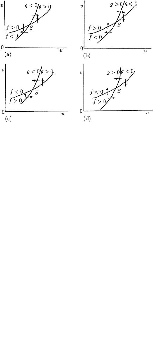
Figure 7.2. Note that Figure 7.2(b) is effectively equivalent to Figure 7.2(a): it is simply
Figure 7.2(a) rotated. Figure 7.2(c) is qualitatively different from the others.
Let us assume that the kinetics f (u,v)and g(u,v) are such that (7.10) has a con-
fined set in the positive quadrant. Then, by the Poincar
´
e–Bendixson theorem, limit cy-
cle solutions exist if (u
0
,v
0
) is an unstable spiral or node, but not if it is a saddle point

7.3 Oscillators and Switches with Two or More Species 227
Figure 7.2. Local behaviour of the reaction null clines f = 0, g = 0 at a steady state S(u
0
,v
0
).
(see Appendix A). For an unstable node or spiral to occur, we require
trA > 0, | A | > 0,(trA)
2
>
<
4| A |⇒unstable
node
spiral
. (7.15)
Consider now Figure 7.2(a). At the steady state (u
0
,v
0
) on each of f = 0and
g = 0 the gradient dv/du > 0 with dv/du]
g=0
> dv/du]
f =0
,so
dv
du
g=0
=−
g
u
g
v
>
dv
du
f =0
=−
f
u
f
v
> 0
⇒|A |=f
u
g
v
− f
v
g
u
> 0,
provided f
v
and g
v
have the same sign. Since dv/du > 0italsomeansthatatS, f
u
and f
v
have different signs, as do g
u
and g
v
. Now from (7.13), trA > 0 requires at least
that f
u
and g
v
are of opposite sign or are both positive. So, the matrix A (the stability
matrix or community matrix in interaction population terms) in (7.12) has terms with
the following possible signs for the elements,
A =
+−
+−
or
−+
−+
(7.16)
with each of which it is possible to have tr A > 0. We have already shown that | A | > 0.
To proceed further we need to know individually the signs of f
u
, f
v
, g
u
and g
v
at the
steady state. With Figure 7.2(a) there are 4 possibilities as illustrated in Figure 7.3.
These imply that the elements in the matrix A in (7.12) have the following signs,
A =
−+
+−
(a)
or
−+
−+
(b)
or
+−
+−
(c)
or
+−
−+
(d)
. (7.17)
For example, to get the sign of f
u
at S in Figure 7.3(a) we simply note that as we move
along a line parallel to the u-axis through S, f decreases since f > 0onthelower
u-side and f < 0 on the higher u-side. If we now compare these forms with those in
(7.16) we see that the only possible forms in (7.17) are (b) and (c). With (d), | A | < 0
228 7. Biological Oscillators and Switches
Figure 7.3. The various possible signs of the kinetics functions f (u,v) and g(u,v) on either side of their
null clines for the case illustrated in Figure 7.2(a). The arrows indicate, qualitatively, directions of typical
trajectories in the neighbourhood of the steady state S.
which makes S a saddle point (which is unstable, of course) and so there can be no limit
cycle solution enclosing S (see Appendix A).
For any given kinetics functions it is easy to determine from the null clines the
qualitative behaviour in the neighbourhood of a steady state, and hence the signs in the
matrix A in (7.12). If the null clines look locally like those in Figures 7.2(b) and (c)
similar results can easily be obtained for the allowable type of kinetics which can admit
periodic solutions for (7.10).
Let us now consider two typical examples which illustrate the qualitative approach
we have just described. Let us suppose a parameter λ of the kinetics is such that the null
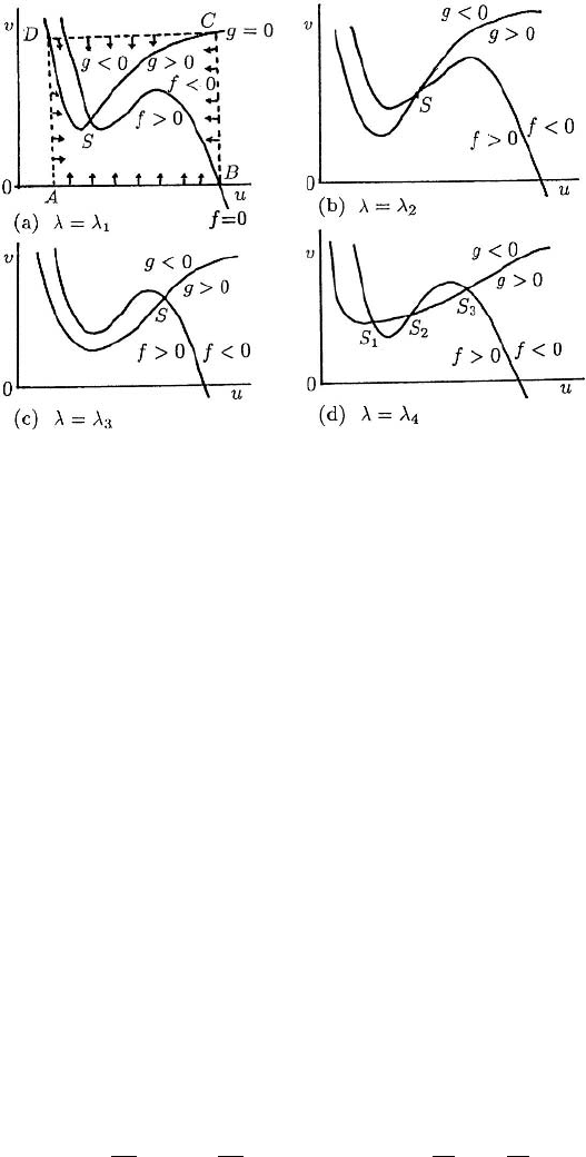
clines for (7.10) look like those in Figure 7.4 for different ranges of the parameter λ.
(This is in fact the null cline situation for the real biological oscillator, Thomas 1975,
briefly discussed in Chapter 6, Section 6.7.) To be specific we choose specific signs for f
and g on either side of the null clines as indicated (these are in accord with the practical
Thomas 1975 kinetics situation). Note that there is a confined set on the boundary of
which the vector (du/dt, dv/dt) points into the set: one such set is specifically indicated
by ABCDA in Figure 7.4(a).
Let us now consider each case in Figure 7.4 in turn. Figure 7.4(a) is equivalent to
that in Figure 7.2(c). Here, in the neighbourhood of S,
dv
du
f =0
=−
f
u
f
v
< 0, f
u
< 0, f
v
< 0,
dv
du
g=0
=−
g
u
g
v
> 0, g
u
> 0, g
v
< 0.
7.3 Oscillators and Switches with Two or More Species 229
Figure 7.4. Qualitative form of the null clines for a specimen kinetics in (7.10) as a parameter λ varies:
λ
1
= λ
2
= λ
3
= λ
4
. With the signs of f and g as indicated, there is a confined set for (7.10): it is, for
example, the rectangular box ABCDA as indicated in (a).
So, the stability matrix A in (7.12) has the signs
A =
−−
+−
⇒ trA < 0, | A | > 0
which does not correspond to any of the forms in (7.16); from (7.13), Re λ<0andso
the steady state in Figure 7.4(a) is always stable and periodic solutions are not possi-
ble for (7.10) in this situation. This case, however, is exactly the same as that in Fig-
ure 7.4(c) and so the same conclusion also holds for it. By a similar analysis we get for
Figure 7.4(b)
A =
+−
+−
which is the same as (c) in (7.17), and is one of the possible forms for (7.10) to admit
periodic solutions.
If we now consider the multi-steady state situation in Figure 7.4(d), we have already
dealt with S
1
and S
3
, which are the same as in Figures 7.4(a) and (c)—they are always
linearly stable. For the steady state S
2
we have
f
u
> 0, f
v
< 0, g
u
> 0, g
v
< 0
0 <
dv
du
g=0
<
dv
du
f =0
⇒ 0 < −
g
u
g
v
< −
f
u
f
v
⇒|A |=f
u
g
v
− f
v
g
u
< 0,
230 7. Biological Oscillators and Switches
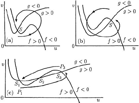
Figure 7.5. Threshold phenomena for various kinetics for (7.10). In (c) a suitable perturbation from one
linearly stable steady state can effect a permanent change to the other stable steady state.
which, from (7.15), shows that the steady state is a saddle point, and although it means
S
2
is unstable, it is the type of singularity which does not admit periodic solutions for
(7.10) according to the Poincar
´
e–Bendixson theorem (Appendix A).
This last case, Figure 7.4(d), is of considerable general importance. Recall the
threshold phenomenon described in the last chapter in Section 6.7. There we saw that
in a situation similar to that in Figures 7.4(a) and (c) that, although the steady state
is linearly stable, if a perturbation is sufficiently large the values of u and v can un-
dergo large perturbations before returning to the steady state (refer to Figure 6.10). This
phenomenon is illustrated in Figures 7.5(a) and (b).
Now consider Figure 7.4(d). S
1
and S
3
are respectively equivalent to the S in Fig-
ures 7.5(a) and (b). We now see, in Figure 7.5(c), that if we perturb (u,v)from say, S
1
to P
1
, the solution trajectory will be qualitatively as shown. Now, instead of returning to
S
1
the solution moves to S
3
, the second stable steady state. In this way a switch has been
effected from S
1
to S
3
. In a similar way a switch can be effected from S
3
to S
1
by, for
example, a perturbation from the steady state S
3
to P
3
. It is possible that a parameter in
the kinetics function g, say, can be varied in such a way that the null cline is translated
vertically as the parameter is, for example, increased. In this case it is possible for the
system to exhibit hysteresis such as we discussed in detail in Chapter 1, Section 1.2
and Chapter 6, Section 6.7. If the reaction kinetics give rise to mushrooms and isolas,
even more baroque dynamic, threshold and limit cycle behaviour is possible. Biological
switches, not only those exhibiting hysteresis and more exotic behaviour, are of consid-
erable importance in biology. We discuss one important example below in Section 7.5.
We also see a specific example of its practical importance in the wave phenomenon ob-
served in certain eggs after fertilization, a process and mechanism for which is discussed
in detail in Chapter 13, Section 13.6 below and Chapter 6, Volume II, Section 6.8.
It is clear from the above that the qualitative behaviour of the solutions can often
be deduced from a gross geometric study of the null clines and the global phase plane
7.3 Oscillators and Switches with Two or More Species 231
behaviour of trajectories. We can carry this approach much further, as has been done,
for example by Rinzel (1986), to predict even more complex solution behaviour of such
differential equation systems. Here I only want to give a flavour of what can be found.
Let us suppose we have a general system governed by
du
dt
= f(u,α),
dα
dt
= εg(u,α), (7.18)
where 0 <ε 1, u is a vector of concentrations and α is a parameter, which is
itself governed by an equation, but which changes only slowly. The fast subsystem
of (7.18) is the O(1) system, as ε → 0, in which α is simply a constant parameter,
since dα/dt ≈ 0. The slow dynamics governs the change in α with time. We analyse
some specific systems like this in the following chapter, when we discuss relaxation
oscillators.
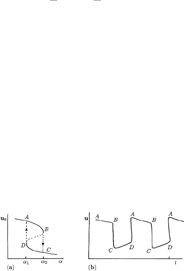
Suppose a uniform steady state u
0
depends on α as indicated schematically in Fig-
ure 7.6(a). That is, there is a region α
1
<α<α
2
where three possible steady states u
0
exist; recall also the discussion in Section 6.7 in the last chapter. To be more specific let
us suppose that α varies periodically in such a way that in each cycle it sweeps back and
forth through the window which gives three solutions for u
0
, the one on the dashed line
in Figure 7.6(a) being unstable as to be expected. At the start suppose α = α
1
and u
0
is
at A in Figure 7.6(a). Now as α increases, u
0
slowly varies until α passes through α
2
.
At α
2
, u
0
jumps discontinuously from B to C, after which it again varies slowly with
α. On the return α-trip, u
0
remains on the lower branch of the S-curve until it reaches
D, where it jumps up to A again. The limit cycle behaviour of this system is illustrated
schematically in Figure 7.6(b). The rapidly varying region is where u drops from B
to C and increases from D to A. This is a typical relaxation oscillator behaviour; see
Chapter 8, Section 8.4 below.
The fast dynamics subsystem in (7.18) may, of course, have as its steady state
a periodic solution, say, u
per
. Now the parameter α affects an oscillatory solution. A
relevant bifurcation diagram is then one which shows, for example, a transition from
one oscillation to another. Figure 7.7(a) illustrates such a possibility. The branch AB
represents, say, a small amplitude stable limit cycle oscillation around u
0
for a given α.
Figure 7.6. (a) Schematic steady state u
0
dependence on the parameter α: steady states on the dashed line
are unstable. (b) Typical limit cycle behavior of u if α slowly varies in a periodic way. The oscillation is
described as a relaxation oscillator: that is, there are slowly varying sections of the solution interspersed with
rapidly varying regions.
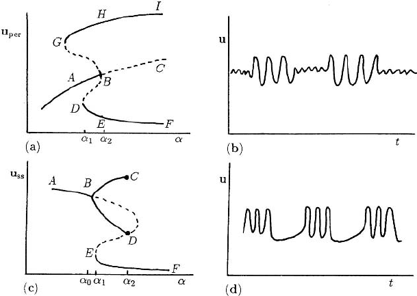
232 7. Biological Oscillators and Switches
Figure 7.7. (a) Schematic bifurcation for periodic solutions of the fast dynamics subsystem of (7.18) as α
varies periodically. The dashed lines are unstable branches. (b) Typical periodic behaviour as α slowly varies
in a periodic way back and forth through the (α
1
,α
2
) window, for the bifurcation picture in (a). (c) Another
example of a periodic solution bifurcation diagram for the subsystem of (7.18) as α varies. (d) Qualitative
periodic solution behaviour as α varies periodically through α
1
and α
2
in (c). These are examples of ‘periodic
bursting.’
Solutions on the branch BC are unstable. Now as α increases there is a slow variation in
the solution until it passes through α
2
at B, after which the periodic solution undergoes
a bifurcation to a larger amplitude oscillation with bounds for u on the curves EF
and HI. The transition from one solution type to another is fast, as in the relaxation
oscillator situation in Figure 7.6. Now let α decrease. The bifurcation to the AB branch
now occurs at D,whereα = α
1
.So,asα varies periodically such that it includes a
window with α<α
1
and α>α
2
, the solution behaviour will be qualitatively like that
shown in Figure 7.7(b).
Figure 7.7(c) shows another possible example. The line AB represents a nonoscilla-
tory solution which bifurcates for α = α
0
to a periodic solution at B. These branches ter-
minate at D and C,whereα = α
2
. The branch EFis again a uniform stable steady state.
Suppose we now consider α to vary periodically between α>α
2
and α
0
<α<α
1
.To
be specific, let us start at F in Figure 7.7(c). As α decreases we move along the branch
FE; that is, the uniform steady state u
ss
varies slowly. At E,whereα = α
1
, the uniform
steady state bifurcates to a periodic solution on the branches BD and BC.Nowasα
increases the periodic solution remains on these branches until α reaches α
2
again, after
which the solution jumps down again to the homogeneous steady state branch EF.A
typical time behaviour for the solution is illustrated in Figure 7.7(d). Both this behaviour
and that in Figure 7.7(b) are described as ‘periodic bursting.’ Keener and Sneyd (1998)
devote a chapter to this phenomenon and describe some specific models of biological
examples where it occurs.
7.3 Oscillators and Switches with Two or More Species 233
The complexity of solution behaviour of such systems (7.18) can be spectacular.
The specific behaviour just described in Figures 7.6 and 7.7 has been found in models
for real biological systems; an example of the former is in the following chapter, while
qualitatively similar curves to those in Figure 7.7 have been found by Rinzel (1985).
The system studied by Rinzel (1985) is specifically related to the model described be-
low in Section 7.5 on neural periodic behaviour. The model system given by (6.125) in
Section 6.7 in the last chapter, and the iodate–arsenous model reaction scheme (6.132)
and (6.133), exhibit comparable solution behaviour but with the potential for even more
complex dynamic phenomena. Othmer and Schaap (1999) discuss the kinetics (firmly
based on the biology) associated with cyclic-AMP emission by cells of the slime mould
Dictyostelium discoideum; see also the article by Dallon and Othmer (1997) who put
forward a discrete cell model for its adaptive signalling. This slime mould exhibits
some remarkable complex dynamics. Decroly and Goldbeter (1987) considered a model
3-variable system associated with cyclic-AMP emission by the cells of Dictyostelium
discoideum as a vehicle to demonstrate the transition from simple to complex oscillatory
behaviour. As well as obtaining increasingly complex patterns of bursting they showed
period doubling leading to chaos; see also Goldbeter (1996).
Figure 7.7 shows some of the complex effects which appear when oscillators inter-
act or when reaction schemes have fast and slow subschemes. This is mathematically
a very interesting and challenging field and one of continuing research. We consider in
some detail some important aspects of oscillator interaction in Chapter 9. In Chapter 12
we discuss another important and quite different aspect of interacting oscillations.
Canards
A canard is the word associated with oscillatory systems which undergo sudden ma-
jor changes in the amplitude and period of the oscillatory solution as some parameter
passes through a narrow range of values. Canards were first discussed in association
with the van der Pol equation by Benoit et al. (1981) and have been studied since in a
variety of applications. Canard systems give rise to interesting and sometimes baroque
dynamical behaviour. The discovery of canards in relatively simple chemical reaction
systems stems from the second half of the 1980’s; one is the two-variable Oregonator
(Brøns and Bar-Eli 1991), a system we discuss in some detail in Chapter 8.
Canards were found by G
´
asp
´
ar and Showalter (1990) in the oscillatory iodate–
sulphite–ferrocyanide reaction, known as the EOB reaction which was discovered by
Edblom and Epstein (1986). The analysis of these sytems can be quite complicated and
analytically interesting since, among other things, they usually involve the interplay of
fast and slow dynamics and hence singular perturbation theory is generally appropriate.
The EOB reaction can be described by a ten-variable empirical-rate-law model system
which like the Belousov–Zhabotinsky reaction (see Chapter 8) can be reduced (G
´
asp
´
ar
and Showalter 1990) in this case to a four-variable system which retains the essential
experimental features of the full system. This four-variable system is given by
A +Y
k
1
k
−1
X, X
k
2
→ Y, 2Y
k
3
→ Z, Z + X
k
4
→ 3Y, Z
k
5
→,

234 7. Biological Oscillators and Switches
where A = SO
2−
3
, X = HSO
−
3
, Y = H
+
and Z = I
2
.G
´
asp
´
ar and Showalter (1990)
used a singular perturbation approach which eliminated the A and Z variables and ob-
tained the minimal set of equations
dX
dt
= k
1
A
s
Y −(k
−1
+k
2
+k
4
Z
s
+k
0
)X,
dY
dt
=−k
1
A
s
Y +(k
−1
+k
2
+3k
4
Z
s
)X − 2k
3
Y
2
+k
0
(Y
0
−Y ),
where A
s
and Z
s
are functions of X and Y given by
A
s
=
k
−1
X + k
0
A
0
k
1
Y +k
0
, Z
s
=
k
3
Y
2
k
1
X + k
5
+k
0
and k
0
, A
0
and Y
0
are constants associated with the experimental parameters. Peng et al.
(1991) analyse this system and other practical model chemical systems which display
canards.
7.4 Simple Two-Species Oscillators: Parameter Domain
Determination for Oscillations
If we restrict our reaction system to only two species it was shown by Hanusse (1972)
that limit cycle solutions can only exist if there are trimolecular reactions. These would
be biochemically unrealistic if they were the only reactions involved, but as we have
shown in Chapter 6 such two-reactant models can arise naturally from a higher-order
system if typical enzyme reactions, for example, are part of the mechanism being con-
sidered. So, it is reasonable to consider trimolecular two-species models and not just for
algebraic and mathematical convenience in demonstrating principles and techniques.
Schnackenberg (1979) considered the class of two-species ‘simplest,’ but chemically
plausible, trimolecular reactions which will admit periodic solutions. The simplest such
reaction mechanism is
X
k
1
k
−1
A, B
k
2
→ Y, 2X +Y
k
3
→ 3X, (7.19)
which, using the Law of Mass Action, results in the nondimensional equations for u and
v, the dimensionless concentrations of X and Y,givenby
du
dt
= a − u +u
2
v = f (u,v),
dv
dt
= b −u
2
v = g(u,v), (7.20)
where a and b are positive constants. Typical null clines are illustrated in Figure 7.8. In
the vicinity of the steady state S these are equivalent to the situation in Figure 7.2(b).
With (7.20) it is easy to construct a confined set on the boundary of which the vec-
tor (du/dt, dv/dt) points inwards or along it; the quadrilateral in Figure 7.8 is one
example. Hence, because of the Poincar
´
e–Bendixson theorem, the existence of a peri-
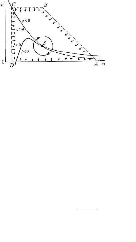
7.4 Simple Two-Species Oscillators 235
Figure 7.8. Typical null clines f = 0and
g = 0 for the ‘simplest’ oscillator (7.20)
for a > 0andb > 0. The quadrilateral
ABCDA is a boundary of a confined set
enclosing the steady state S.
odic solution is assured if, for (7.20), the stability matrix A for the steady state satisfies
(7.15).
Determination of Parameter Space for Oscillations
For any model involving parameters it is always useful to know the ranges of parameter
values where oscillatory solutions are possible and where they are not. For all but the
simplest kinetics this has to be done numerically, but the principles involved are the
same for them all. Here we carry out the detailed analysis for the simple model reaction
(7.20) to illustrate the general principles: the model involves only two parameters a and
b and we can calculate the (a, b) parameter space analytically. The requisite space is
the range of the parameters a and b which make the steady state an unstable node or
spiral: that is, the parameter range where, from (7.15), trA > 0and| A | > 0. Later we
shall develop a more powerful and general parametric method which can be applied to
less simple kinetics.
The steady state (u
0
,v
0
) for (7.20) is given by
f (u
0
,v
0
) = a − u
0
+u
2
0
v
0
= 0, g(u
0
,v
0
) = b −u
2
0
v
0
= 0,
⇒ u
0
= b +a,v
0
=
b
(a + b)
2
, with b > 0, a + b > 0.
(7.21)
Substituting these into the stability matrix A in (7.12), we get
trA = f
u
+ g
v
= (−1 + 2u
0
v
0
) +(−u
2
0
) =
b −a
a + b
−(a + b)
2
,
| A |=f
u
g
v
− f
v
g
u
= (a + b)
2
> 0foralla, b.
(7.22)
The domain in (a, b) space where (u
0
,v
0
) is an unstable node or spiral is, from (7.15),
where trA > 0 and so the domain boundary is
trA = 0 ⇒ b −a = (a +b)
3
. (7.23)
Even with this very simple model, determination of the boundary involves the so-
lution of a cubic, not admittedly a major problem, but a slightly tedious one. Care has
