Microwave Journal 2011 №04
Подождите немного. Документ загружается.


RFMD
®
.
Integrated Synthesizer/Mixer Solutions
RFMD offers the widest portfolio of highly integrated frequency conversion devices
designed to reduce development time, risk, and size in modern RF transmitters and
receivers. They combine a high-performance fractional-N phased looked loop, wideband
VCOs, LO buffers, and RF mixers on a single chip. The RF205x family has been
optimized for low current consumption while providing a stable, low noise synthesizer
with integrated up and down conversion mixers.
The RFFC207x and RFFC507x series take advantage of an advanced sigma-delta PLL
modulator that delivers outstanding synthesizer phase noise performance with an rms
integrated phase error as low as 0.18 degrees at 1 GHz. Designed to address the need
for highly flexible and reusable solutions, these devices offer an extended LO tuning
range and RF mixer frequency range and can be configured to work as signal sources by
bypassing the integrated mixers. For applications requiring the use of multiple frequency
converters, the novel “multi-slice” mode allows up to 4 devices to share a common serial
bus without the need for separate chip-select control lines between each device and the
host controller, saving cost and simplifying the final design.
Order RFMD products online at www.rfmd.com/rfmdExpress.
For sales or technical support, contact your authorized local sales representative (see www.rfmd.com/globalsales).
Register to receive RFMD’s latest product releases with our Email Component Alerts at www.rfmd.com/emailalert.
7628 Thorndike Rd., Greensboro, NC 27409-9421 USA • Phone 336.664.1233
RFMD
®
is a trademark of RFMD, LLC. All other trade names, trademarks and registered trademarks are the property of their respective owners. ©2011 RFMD.
These products comply with RFMD’s green packaging standards.
SPECIFICATIONS
Part
Number Architecture
Block
Diagrams
A, B, C
LO Freq
(MHz)
Phase Noise
(dBc/Hz)
at 2 GHz
Mixer
RF/IF Port
Freq Range
(MHz)
Mixer
IIP3
(dBm)
Supply
Voltage
(V)
Supply
Current
(mA)
with one
mixer active
Multi-
Slice
Mode
1 kHz 10 kHz
RF2051 Frac-N PLL, VCO, 2 mixers A 300 to 2400 -85 -90 30 to 2500 18 2.7 to 3.6 55 to 75 —
RF2052 Frac-N PLL, VCO, 1 mixer B 300 to 2400 -85 -90 30 to 2500 18 2.7 to 3.6 55 to 75 —
RF2053 Frac-N PLL, 1 mixer C external VCO -85 -90 30 to 2500 23 2.7 to 3.6 45 to 65 —
RF2056 Frac-N PLL, VCO, 2 mixers A 50 to 500 — — 30 to 500 25 2.7 to 3.6 50 to 65 —
RF2057 Frac-N PLL, VCO, 2 mixers A 1900 to 2400 -85 -90 30 to 2500 18 2.7 to 3.6 55 to 75 —
RF2059 Frac-N PLL, VCO, 2 mixers A 1550 to 2050 -85 -90 30 to 2500 18 2.7 to 3.6 55 to 75 —
NEW RFFC2071 Frac-N PLL, VCO, 2 mixers A 85 to 2700 -95 -102 30 to 2700 23 2.7 to 3.3 100 to 130
P
NEW RFFC2072 Frac-N PLL, VCO, 1 mixer B 85 to 2700 -95 -102 30 to 2700 23 2.7 to 3.3 100 to 130
P
NEW RFFC5071 Frac-N PLL, VCO, 2 mixers A 85 to 4200 -95 -102 30 to 6000 23 2.7 to 3.3 100 to 135
P
NEW RFFC5072 Frac-N PLL, VCO, 1 mixer B 85 to 4200 -95 -102 30 to 6000 23 2.7 to 3.3 100 to 135
P
A B C
Order RFMD products online at www.rfmd.com/MWJ0411.
FEATURES
• Fractional-Nsynthesizerwithultra-ne
1.5 Hz step size and low spurious products
• Very wideband low noise VCOs
• 52 MHz phase detector frequency
• Programmable LO output dividers
• Active high-linearity RF mixers with
adjustable bias for low power operation
• Full duplex mode (dual mixer versions)
with minimum 60 dB mixer-to-mixer
isolation
• Up to 6 general purpose outputs
(RFFC family)
• 3 V supply voltage
• Low current consumption
• 3-wire serial programming interface
• Applications include: CATV head-ends;
multi-dwelling broadcast distribution
systems; satellite IF channel stacking;
point-to-point radios; GSM, CDMA,
WCDMA, TD-SCDMA and LTE repeaters;
frequency band-shifters; software
denedradios
RFMD_Integrated RF FC Solutions_MWJ_print_0411.indd 1 3/11/2011 2:37:55 PM
MWJRFMD_SOLUTIONS0411.indd 61 3/25/11 2:09 PM
62 MICROWAVE JOURNAL APRIL 2011
Special RepoRt
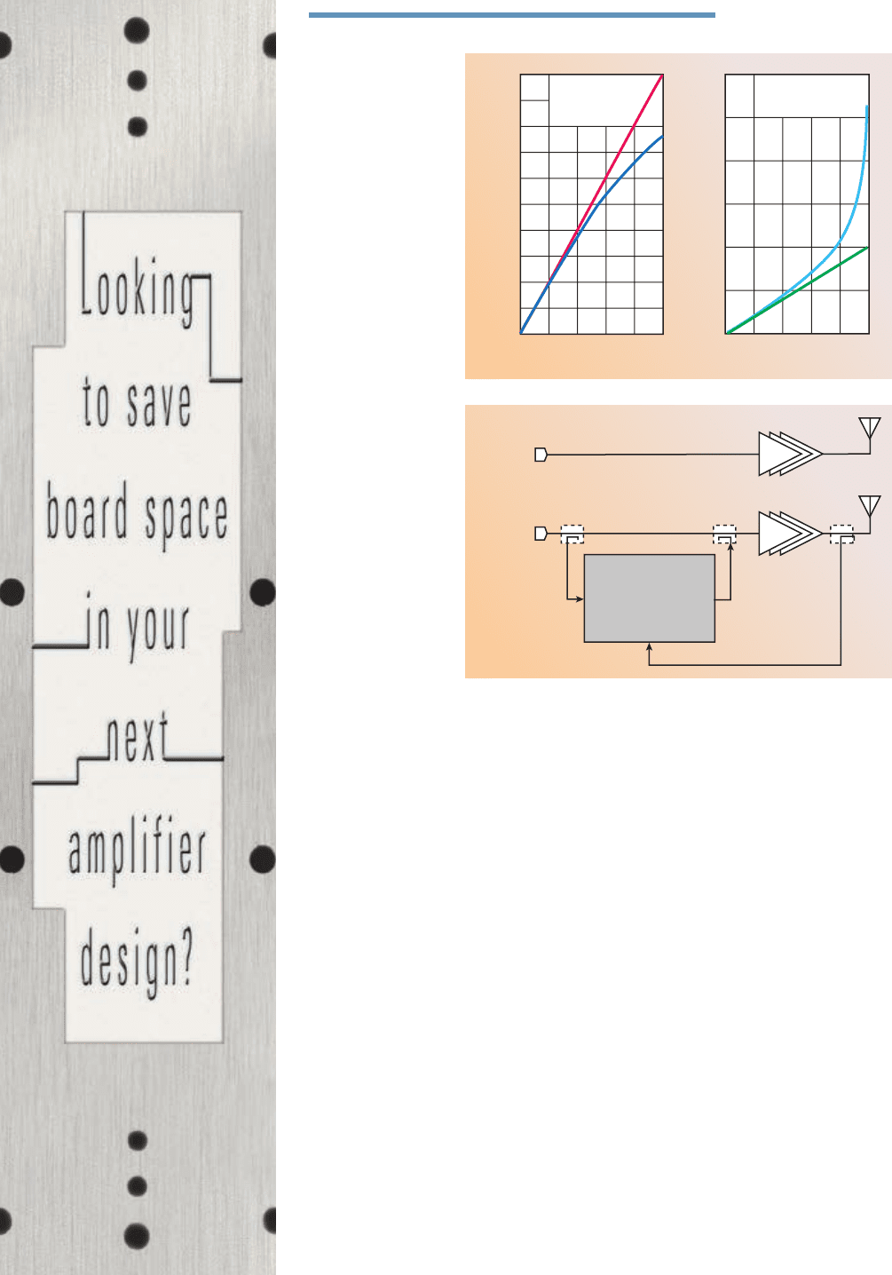
On the left-hand side, the red signal
is the input applied to the PA. The
blue curve shows the output of the
PA. Where a straight line following
the red line is expected, one can see
that as the signal becomes larger, the
amplifier is not able to follow the in-
put anymore; it is compressing. On
the right-hand side, the input signal is
predistorted (cyan) and the output of
the PA (green) is now a straight line;
the PA is said to be more linear. It is
interesting to note that while the blue
line was pointing down, the green line
is pointing up; it is expanding.
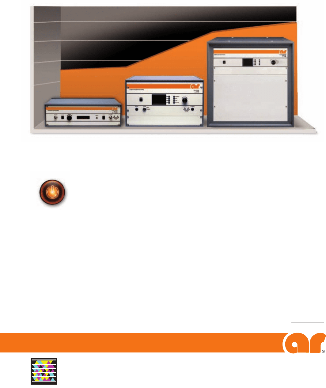
Implementation
Following the predistortion prin-
ciple, the actual implementation of an
analog PD solution is very straightfor-
ward and can be hooked up in a few
minutes to any existing PA. �Figure�
2 illustrates the simplicity of such a
system. The RF input signal RFIN
is connected to the analog predis-
torter’s input, called RFIN (coupler
A). The predistorted signal coming
out of RFOUT is added (coupler B)
purpose, linearity
can be defined as
a metric that mea-
sures the quality of
the signal after be-
ing distorted by an
amplifier.
The last goal is
the video band-
width (VBW). In
a nutshell, higher
VBW means more
users and higher
data rates from the
end user’s favorite
smartphone.
While the first
cellular standards
like GSM were cre-
ated to simply make
phone calls, modern
standards like 3G
and 4G have been
primarily developed
to handle greater
data transmission
and ultimately give
users access to new
services such as vid-
eo streaming. The
shift to those mod-
ern air interfaces
has changed the PA
requirements quite
substantially. W-CMDA, for instance,
calls for VBWs that are at least ten
times greater than GSM. Worse, in or-
der for a 3G-PA to be properly linear-
ized, its VBW should be even greater
because the linearizer will expand the
signal, as will be discussed later in this
article.
Predistortion’s PrinciPle
and imPlementation
Principle
Predistortion (PD) is basically a
way of improving the linearity of the
PA. Why is that a good thing? Because
linearity can be traded for power ef-
ficiency. A good PD system allows the
PA designer to make the PA less lin-
ear but more efficient, knowing that
the lost linearity can be recovered by
the linearizer. The PD principle is ex-
tremely simple and has given its name
to the technique. The idea is to pre-
process, or predistort, the signal ap-
plied to the PA, rather that trying to
improve the PA itself.
Figure� 1 shows this principle.
s Fig. 1 PA distortion.
1.0
0.9
0.8
0.7
0.6
0.5
0.4
0.3
0.2
0.1
0
3.0
2.5
2.0
1.5
1.0
0.5
0
1.01.00.80.60.40.20 0.80.60.40.20
INPUT
PA OUTPUT
INPUT SIGNAL
PA OUTPUT
PREDISTORTED
INPUT SIGNAL
INPUT
OUTPUT
OUTPUT
s Fig. 2 Predistorter (SC1887) application schematic.
RFIN
RFOUT
RFFB
SC1887
RF INPUT
RF INPUT
PA
PA
A B
C
4M31 FINAL.indd 62 3/25/11 2:19 PM

800-411-6596
>
www.anaren.com
In Europe, call 44-2392-232392
ISO 9001 certified
Visa/MasterCard accepted (except in Europe)
Measuring only 6.35 x 5.08mm (P-size) or 14.2 x 5.1mm
(E-size), Anaren’s revolutionary new SMT Doherty combiners
are up to 1/10
th
the size of printed Doherty implementations.
That’s valuable space you can use for other functionality or
a smaller overall amp design.
Beyond a smaller footprint, these new parts also offer you:
> Low insertion loss – in a fraction of the space,
achieve the same loss you’d get with thick, expensive,
high-performance PCB
> Superior unit-to-unit consistency – Xinger parts
are pre-tested and offer highly repeatable performance
compared to the variability seen with low-cost PCB
manufacturing
> The option to choose less costly PCB – switching
to an SMT solution lets you use a standard FR4-type
board material (no more of overcompensating
for poor insertion loss of printed combiners
by using top-of-the-line board)
> High reliability – our softboard SMT solution
matches the CTE characteristics of PCB
> Xinger-brand Doherty splitters available,
too – save time and trouble, with our 5dB
P-size couplers for asymmetrical Doherty
implementations!
To learn more, receive complete
specs, obtain a quote, or get a free
test board (qualifi ed prototypes only),
email sales@anaren.com today
or visit www.anaren.com
vs.
Xinger Doherty
Combiner
“Best-case” Printed
Doherty Combiner
14.2
5.1
16.5
16.5
BELOW: Our 1960MHz Xinger-brand Doherty combiner is
approx 1/4 the size of a PCB Doherty (expressed in mm)
Try our new, Xinger
®
-brand
Doherty combiner on for size!
MWJANAREN04111.indd 63 3/25/11 2:09 PM

5 demonstrates a possible implemen-
tation of such a polynomial. The input
signal X is passed through a number
of multipliers to generate its harmon-
ics: X, X
2
, …, X
n
. Those harmonics are
then multiplied by a series of coeffi-
cients c
1
, c
2
,…, c
n
and finally summed
together to create a polynomial of the
form: c
1
X + c
2
X
2
+…+ c
n
X
n
.
In DPD, these operations are re-
alized in the digital domain. Analog
predistortion is using analog multipli-
ers and digital-to-analog-converters
(DAC) for the coefficients.
One fundamental mechanism of
the PA is the so-called memory effect.
In a nutshell, the PA transfer function
is not constant over time and will vary.
In other words, the output of the PA
to RFIN at the input of the PA. A
last signal called RFFB (coupler C)
is used to analyze the output of the
PA and adapt the predistortion sig-
nal. It should be noted that unlike in
a digital PD system, all of the inputs
and outputs are RF/analog signals.
Among other things, this makes it in-
dependent of protocol. Any adaptive
PD system, analog or digital, requires
two main subsystems: an analyzing
and processing engine and a correc-
tion engine.
Analyzing and Processing Engine
The first thing that needs to be
done is analyzing the signal to extract
metrics that describe the quality of the
incoming signals RFIN and RFFB.
These metrics are called cost func-
tions (CF). RFIN is the signal sent
by the transceiver to the input of the
PA. As such, this signal has the highest
spectral purity, that is free of distor-
tion and only limited in quality by the
transmitter baseband and upconvert-
er. RFFB is basically the output of the
PA, only attenuated to accommodate
the power levels at the input of the
linearizer. This signal is strongly dis-
torted by the PA. It is the signal that
must be improved. Having these two
inputs allows a few operations, such as
subtracting them to obtain the error
introduced by the PA (see Figure 3).
It is also possible to take a look at
RFFB and measure its spectral purity
by measuring the energy in the band
of interest and out of the band. Fig-
ure 4 shows the measured adjacent
channel leakage ratio (ACLR) output
of a PA for a single-carrier W-CDMA
signal.
Correction Path
The correction block is the heart of
the system. Its role is to apply mathe-
matical transformations to the incom-
ing RF signal. These transformations
are called the work function (WF).
The work function is an approximation
of the PA’s inverse transfer function.
Ideally, the predistorting transforma-
tion is cancelled out by the amplifier’s
distorting transformation, resulting in
an undistorted, amplified output sig-
nal. Due to the nonlinear behavior of
the PA, its inverse function can be ap-
proximated by a polynomial function;
the higher the order of the polynomi-
al, the better the approximation of the
mathematical transformation. Figure
LNAs
LC And Cavaty Filters
Power Amplifiers
Frequency range from DC up to
18GHz and power up to 1000W
and more......
www.jelang.com
Tel : +1 425 444 2375
Bothell, WA 98021, USA
22745 29th Drive SE, Suite 200,
Sales and Technical Support:
Elektrobit Inc.
Fax : +1 425 686 3102
Email: jelang@elektrobit.com
Website : www.elektrobit.com
RF Solutions
High Quality
/
/
Low Cost
2 Year Warrantee
Quick Delivery
Special RepoRt
64 MICROWAVE JOURNAL APRIL 2011
s Fig. 3 Error measurement.
1.0
0.9
0.8
0.7
0.6
0.5
0.4
0.3
0.2
0.1
0
1.00.80.60.40.20
INPUT
IDEAL OUTPUT
PA OUTPUT BEFORE PD
ERROR SIGNAL
OUTPUT
s Fig. 4 In-band vs. out-of-band.
30
20
10
0
–10
–20
–30
–40
151050–5–10–15
PA OUTPUT POWER
(
dBm/30 kHz
)
FREQUENCY OFFSET FROM
CARRIER CENTER (MHz)
IN BAND
OUT BAND
s Fig. 5 Polynomial generation.
OUT
X
X
2
X
3
X
4
X
5
X
6
C
1
C
2
C
3
C
4
C
5
C
6
4M31 FINAL.indd 64 3/25/11 2:20 PM

Handheld Spectrum Analyzers N9340B NEW N9342C
Frequency range 100 kHz – 3 GHz 100 kHz – 7 GHz
Task planner and internal GPS No Yes
Weight 7.7 lbs 8.1 lbs
Dimensions 12.5"x 8.15"x 2.7" 12.5"x 8.15"x 2.7"
So does every minute you save.
Making complex measurements simple and reliable is what Agilent
handheld spectrum analyzers (HSA) are all about—rain or shine, day
or night. Automated functions reduce human error and save time.
Agilent’s new N9342C 7 GHz HSA even stores multiple test routines
so repetitive tasks can be quickly executed. MIL-rugged, superb
ergonomics and feature-rich. That’s fi eld ready. That’s Agilent.
© 2010 Agilent Technologies, Inc.
* With purchase of an N9340B or
N9342C HSA.
Promotion ends May 31, 2011.
In the fi eld, every measurement counts.
Agilent and our
Distributor Network
Right Instrument.
Right Expertise.
Delivered Right Now.
FREE spare battery, battery charger
and 12 V adapter with purchase
*
Learn more at www.newark.com/Agilent_HSA
800-463-9275
www.newark.com/agilent
06467_MJ_HHSA_Newark_March
Docket/Job: 06467
Client: Agilent
Trim: 7.8125" (w) x 10.75" (h)
Safety: 7.125" x 10.125"
Bleed: .25"
Publication: Microwave Journal
Insertion Date: March 2011 Issue
Colours: CMYK
Art Director: Client
Copywriter: Client
Mac Artist: Julie
Proof printed
at 100 %
06467_MJ_HHSA_Newark_March.indd 1 11-01-28 4:06 PM
MWJAGILENT0311.indd 65 3/25/11 2:09 PM

identical, but is fed by a time shifted
version of the input signal X. Such a
mathematical representation is called
a Volterra Series and was developed
by Vito Volterra in 1887. The analog
predistorter contains four memory
terms. Each of them is made of a pro-
grammable delay, followed by a 6
th
or-
der polynomial.
Ad aptation Related Issues
The system must be continuously
adaptive to compensate for changes.
It basically learns
from its mistakes
and becomes bet-
ter over time. When
the device starts, it
waits for an input
signal and then goes
through an adapta-
tion loop (see Fig-
ure 8). When the
adaptation is over
after a few seconds,
the device will go
into power saving,
but will keep looking
at the incoming signal regularly and
immediately go back to adaptation if
necessary.
The adaptation principle is quite
simple. Starting with some random
coeffi cients, a few sets of random co-
effi cients are applied and the result
measured. Out of these trials, the best
coeffi cients are selected, and the loop
is repeated until the linearity target is
reached.
This algorithm, while being robust
and simple, puts a high burden on
the analog blocks on the chip. When
the device enters the ‘sleep state’, the
on-chip temperature drops by a few
tens of degrees Celsius. These tem-
perature changes are happening many
times per second and should have no
impact on the analog path in order for
the PD signal to stay constant.
Also, during adaptation, the algo-
rithm applies random coeffi cients on
the online signal, the signal sent to
the PA. If too much of the perturba-
tion energy is applied, the PA linearity
will degrade and violate the spectrum
requirement. On the other hand, if
the applied perturbation is too small,
the cost function will not change sig-
nifi cantly enough to be meaningful,
hence useful for adaptation. In order
for this mechanism to work, the gain
settings throughout the chip have to
depends on its input at all times. Fig-
ure 6 shows how the PA characteristic
is affected by the memory effect; its
output spreads.
To accommodate for these memory
effects, the polynomial has to be re-
placed with a set of polynomials (see
Figure 7). Each of the polynomials is
SPECIAL REPORT
66 MICROWAVE JOURNAL APRIL 2011
Fig. 6 Memory effect.
PA OUTPUT
0.8
0.7
0.6
0.5
0.4
0.3
0.2
0.1
0
1.00.80.6
0.4
0.20
INPUT
OUTPUT
Fig. 7 Memory compensation.
c
1
X+c
2
X
2
+…+c
n
X
n
d
1
X+d
2
X
2
+…+d
n
X
n
e
1
X+e
2
X
2
+…+e
n
X
n
f
1
X+f
2
X
2
+…+f
n
X
n
OUT
X
τ
1
τ
2
τ
3
τ
4
Fig. 8 Adaptation algorithm.
WAIT FOR
SIGNAL
ITERATION=0
GENERATE
RANDOM
COEFFICIENTS
APPLY
COEFFICIENTS
ITERATION
= N?
APPLY BEST
COEFFICIENTS
MEASURE PA
DISTORTION
MEASURE PA
LINEARITY
TARGET
REACHED?
SLEEP
YES
NO
NO
ITERATION+1
SAVE
COEFFICIENTS
YES
4M31 FINAL.indd 66 3/25/11 2:22 PM

Absorbed Radiation (SAR value) in a Human Head.
Capture the Concept.
With COMSOL Multiphysics
®
you are empowered to build the simulations
that accurately replicate the important characteristics of your designs.
The key is the ability to include all physical effects that exist in the real
world. This multiphysics approach delivers results—tangible results that
save precious development time and spark innovation.
© 2011 COMSOL. COMSOL AND COMSOL MULTIPHYSICS ARE REGISTERED TRADEMARKS OF COMSOL AB.
CAPTURE THE CONCEPT IS A TRADEMARK OF COMSOL AB. OTHER PRODUCT OR BRAND NAMES ARE
TRADEMARKS OR REGISTERED TRADEMARKS OF THEIR RESPECTIVE HOLDERS.
Currents, Fields and Waves Simulation
www.comsol.com/showcase/em
Watch Tutorial
MWJCOMSOL0411.indd 67 3/25/11 2:09 PM

put signal, the linearizer should have a
280 MHz VBW. This also implies that
the PA has a VBW high enough to al-
low the correction signal to be passed
to its output.
Squa re-cube Law Factor Dilemma
While being extremely simple, the
square-cube law has dramatic conse-
quences on all physics phenomena.
This law teaches that certain forces
will matter more or less depending on
the magnitude of a particular physics
quantity. What does this all have to do
with the topic? Take a 1 V sinusoid
and square it. This would be the sim-
plest way to generate the second har-
monic of the signal. The output signal
will be 1 V (see Figure 9). Now, do
the same thing with a 10 and 0.1 V
signal. The outputs will be 100 and
10 m V, respectively. In the fi rst case,
the output of the multiplier expanded
— 100 V > 1 V — and in the second,
the signal has been severely com-
pressed — 10 mV < 0.1 V.
What this means is that for ‘larger’
input signals, the polynomial genera-
tor output will be rapidly overwhelmed
while smaller signals will virtually
vanish. Solutions to the expansion
are two-fold: increasing the dynamic
range and increasing the resolution of
the coeffi cient DACs. The compres-
sion issue can only be resolved by am-
plifying the signal, that is adding gain.
A high gain can be achieved using a
cascade of amplifi cation stages with
the drawback that each stage requires
power and adds noise. Low noise am-
plifi cation is therefore a must.
Peak -to-Average Ratio Burden
The peak-to-average ratio (PAR)
is the ratio between the peak of the
signal and its average. In Figure 10,
a short time sample of a four carrier
W-CDMA signal with a 10 dB PAR
is shown. A single peak above 0.7 can
be seen, while most of the signal (the
average) is much lower. Multicarrier
applications, modern standards and
OFDM, in particular, lead to very high
PAR. What is important to understand
from a design standpoint is that the
analog circuits within the linearizer
basically have the same problem as the
PA. They have to support a high dy-
namic range to accommodate the PAR.
Worse, because the linearizer has to
create high order correction terms for
the polynomial, it will actually expand
be tightly controlled over process,
voltage and temperature (PVT). Only
a tight control will ensure that the per-
turbation energy is controlled.
DESI GN ISSUES EXPLAINED
Bandwidth Expansion
Predistortion is all about signal
expansion, hence bandwidth expan-
sion. For a given input signal at a fre-
quency f
0
, the PA will generate dis-
tortion products at multiples of this
frequency: 2f
0
, 3f
0
, 4f
0
, 5f
0
, 6f
0
, 7f
0
,
etc. While this is a good thing for a
rock guitar, modern telecommunica-
tion PA spectral output requirements
are very stringent and do not tolerate
too much distortion. The higher order
harmonics’ energy is high enough to
signifi cantly degrade the spectrum up
to the 7
th
order.
This means the linearizer should
be able to generate frequencies at
least up to 7f
0
to cancel this distortion
product at the output of the PA. In
other words, for a 40 MHz VBW in-
SPECIAL REPORT
68 MICROWAVE JOURNAL APRIL 2011
Fig. 9 Compression vs. expansion.
angle (rad)
max(sin(x)) = 10 V
max(sin(x)) = 1 V
sin(x) sin(x) * sin(x)
angle (rad)
max(sin(x)) = 0.1 V
angle (rad)
1
0
–1
0.1
0
–0.1
100
50
0
–50
1086420
1086420
67543210
AMPLITUDE (V)
AMPLITUDE (V)
AMPLITUDE (V)
Fig. 10 Peak to average ratio.
0.7
0.6
0.5
0.4
0.3
0.2
0.1
0
TIME 10
–3
4 CARRIERS W-CDMA, PAR = 9.99
5.545.505465.425.38
AMPLITUDE
4M31 FINAL.indd 68 3/25/11 2:24 PM
rf/microwave instrumentation
Other ar divisions: modular rf • receiver systems • ar europe
USA 215-723-8181. For an
applications engineer, call 800
-
933
-
8181.
In Europe, call ar United Kingdom 441-908-282766 • ar France 33-1-47-91-75-30 • emv GmbH 89-614-1710 • ar Benelux 31-172-423-000
ISO 9001:2008
Certified
Copyright © 2011 AR. The orange stripe on AR products is Reg. U.S. Pat. & TM. Off.
Once again AR has turned up the power on our “S” Series 0.8-4.2 GHz solid-state amplifiers.
Recently we made them smaller and lighter, with more power. Now we’ve added
more power without increasing size or weight.
One thing we didn’t change was something we call Subampability:™ giving you expandable power.
It’s a unique money-saving feature that lets you add amplifiers when you need more power.
And you can use these amps independently for tests that don’t require as much power.
AR products are backed by the best and most comprehensive warranty in the industry.
We back them better because we build them better. And we support our customers with a global
network that reaches the far corners of the world.
So when you need a new power amplifier, there are some very powerful reasons to
choose an “S” Series amp from AR.
Visit us at http://goo.gl/nVyFu or call 215-723-8181.
Our Newest “S” Series Amps Now Offers Powers From 20 To 1200 watts, And Everything In Between.
More Power To You!
Microwave_Journal_More_Power:Layout 1 3/21/11 2:17 PM Page 1
MWJAR0411.indd 69 3/25/11 2:10 PM
70 MICROWAVE JOURNAL APRIL 2011
Special RepoRt
TARGET YOUR
VALUE ADD SERVICE
NEEDS!
Teledyne Cougar is your source for Integrated Subassemblies, RF & Microwave
Components, Integrated Assemblies and Value-added Service needs.
ISO 9001:2008 • AS9100
MIL-PRF-38534 • Class H & Class K Certified
927 Thompson Place • Sunnyvale, CA 94085 • 408-522-3838 • Fax 408-522-3839
www.teledyne-cougar.com • email: cougar@teledyne.com
Teledyne Cougar offers a complete range of transistor, FET, and MMIC
die services, and provides a one-stop shop for all of your value add
requirements
.
Die Packaging, Sorting, Testing
Microcircuit and Semiconductor
Die Evaluation
Environmental Screening
Electrical Test Capabilities
Cougar supports standard military specifications, and customer proprietary requirements. We
offer full-service MIL-PRF-38534, MIL-PRF-38535, MIL-PRF-19500, and MIL-STD-883 screening
and program management capability.
Passive Element, Substrate,
and Package Eval.
Standard Hybrid Assembly - Build to Print
Standard Hybrid Screening Flow
Custom and Standard Packaging
HFEValueAdd1-11_Transcom 3/8/11 10:01 AM Page 1
nal drops at a very fast pace because
each time the input signal is squared,
the output is an order of magnitude
smaller than the input. In order to
compensate for these losses, at least
20 dB gain must be added after each
squaring function.
CirCuit Limitations and
Considerations
Linearity of the MOS Device
With all its advantages, the MOS
transistor is not a very linear device;
its well-known square law V-I relation-
ship limits its usability where linear
transconductance stages are needed.
In other words, independent of the
load or type of circuit used, one can-
not apply a 1 V signal at its gate and
expect 60 dB linearity at its output; 10
to 20 dB is all one will get.
The most widely used techniques
to overcome this limitation are to use
the transistor in a closed-loop circuit.
Closing the loop reduces the input sig-
nal seen by the transistor to a few tens
of a mV, while keeping a large output
signal and ultimately improving its lin-
earity. As everything in life, however,
this does not come for free. Closed-
loop circuits are relying on feedback
to work and feedback always comes
too late. Given BW and gain require-
ments, applying feedback would have
been difficult, and perhaps even im-
possible. To rely exclusively on open-
loop circuitry was preferred.
Process, Voltage and Temperature
Variation Impact
Dealing with process, voltage and
temperature variations is the essence
of an analog designer’s job. Process
variations come from the imperfect
manufacturing of silicon structures.
The outcome is that the devices that
are fabricated will vary from wafer to
wafer.
Voltage variation can be mostly
handled by architecture choice and
has little impact on most of the im-
portant design parameters other than
As can be seen, when the order of
the signal increases, the average sig-
the PAR. Table 1 demonstrates this
expansion for a 10 dB PAR signal.
taBLe i
Par
Signal PAR (dB) PAR Peak (V) Average (V)
1
st
order 10 3.16 1 0.316
2
nd
order 20 10 1 0.1
4
th
order 40 100 1 0.01
6
th
order 60 1000 1 0.001
taBLe ii
Gain variation over temPerature
Temperature
(˚C)
Gain X (V) X
2
(V) X
3
(V) X
4
(V)
-40 25 0.1 0.25 0.6 1.5
25 15 0.1 0.15 0.22 0.34
125 10 0.1 0.1 0.1 0.1
4M31 FINAL.indd 70 3/25/11 2:24 PM